Electronics Production
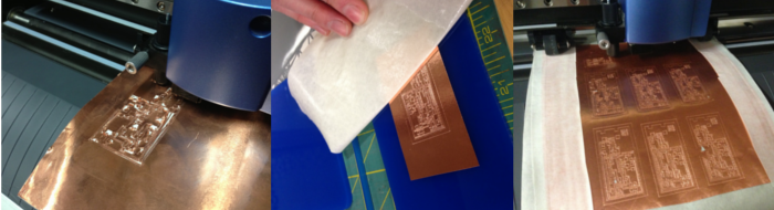
This week we just received our Modela machine, and worked on setting it up. However, we still did not receive our rigid PCB material, so we have not yet been able to start milling the circuit. So we decided to try an alternate option- vinyl cut circuits.
I spent a while testing circuits on the vinyl cutter. After many iterations of changing the blade depth and pressure, I got closer to making a successful circuit. However, I was still unable to weed one out successfully. They would either not cut completely through, or they would begin to shred. I last tried following Mercedes Mane's Fab tutorial, where she removed the backing from the foil, placed it on the transfer paper, and cut sticky side up. Unfortunately, the results were still unsatisfactory.
Update
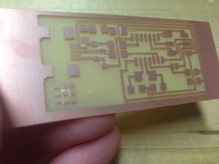
OK so it's about two weeks later but we finally received our PCB material! I ended up using the Roland software, as I have not yet been able to set up fab modules. The first few attempts at cutting completely failed. One of the biggest issues was figuring out how to make the traces thin enough so that they didn't run together, while also making sure that they were thick enough so that they could not easily be broken. I am still not sure I completely understand the "pitch" setting, but I found that setting pitch to .004 worked well. .003 was a little too thin, and .006 was too thick ad the traces ran together.
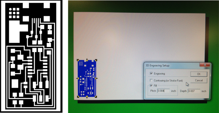
 Roland's 3D Engrave software and the resulting board
After a few failed attempts, I finally found some good settings:
> Save the fab_isp .png file as a .bmp in Photoshop (could maybe also use GIMP).
> Crop white border off of the image and measure it (you will need to input the size when you import into 3D Engrave.
> Set the z-zero point on the machine. An easy way to do this is to bring the bit down close to the material, and then loosen the set screw so that the bit drops down the rest of the way. You may want to put a piece of paper under the bit, then pull it away after it drops to prevent the bit from chipping.
3D Engrave:
File> Import> .bmp
Rt. click on the image> Convert to Polygons> convert contours of bitmap colors to polygons
The image will resize itself, so rt. click> Properties> change size to match the original size that you measured in Photoshop, also change the color to black
This will make a new copy over the first one, so delete the first image
Select image> Create 3D Engraving Path> put a check next to Engraving and Fill, and set the Pitch to .004 and the depth to somewhere around .01
This brings you into the 3D View tab. Double check to make sure toolpaths look OK
Go back to 2D View tab
File> Output Device Setup> Properties
> Size: Change to match material size
> Tool:Select black tab, change material to aluminum,
Save File
Start Cutting
Success!
Update
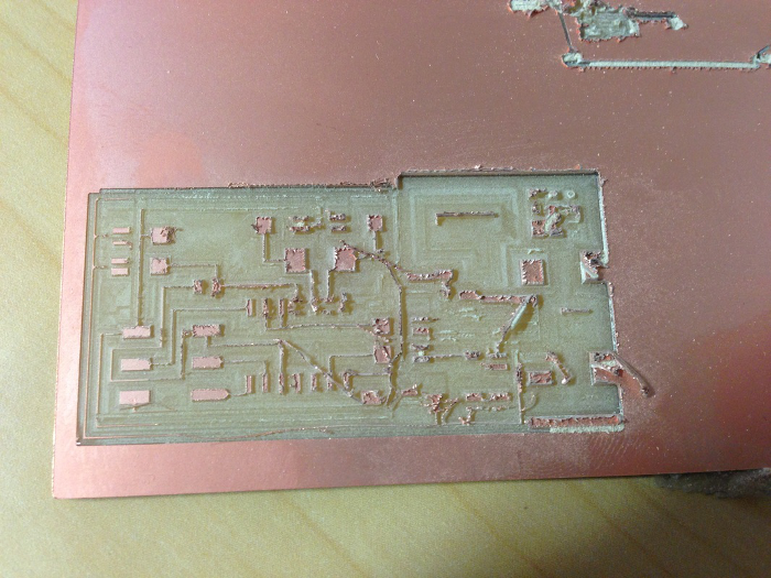
Since trying to mill the board with the Roland software, we were finally able to install fab modules! MUCH easier to use and much more reliable. Using Roland's software, we broke quite a few bits, and only about 25% of the boards would be usable. There were always stray toolpaths that cut diagonally across the board, rendering it useless. In addition, Fab Modules had all of the proper speed and feed presets, all we had to do was choose the bit size, and we were able to mill the boards in a fraction of the time.
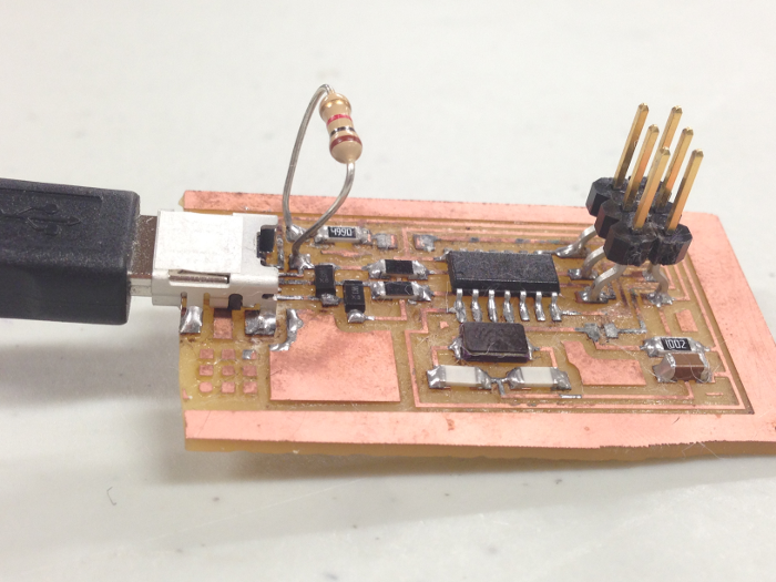
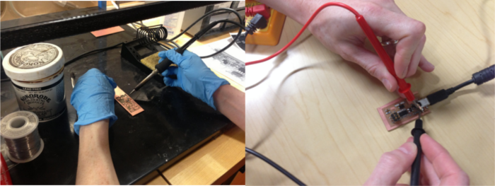
Stuffing the Board
I have soldered many times before, but only a few times with electronics. I followed the Adafruit Guide to Excellent Soldering which helped a lot. I used flux-core solder, however, I was having some difficulty getting the solder to flow properly so I cheated and used flux paste as well.
Programming the Board
Programming with AVR dude I initially tried to program the board with Avrdude:
Windows key +r opens terminal; cmd; avrdude; cd desktop; cd firmware; make clean; make hex; Make fuse; Make program
However, I kept getting stuck at "make fuse". My first attempt I somehow blew the fuses- oops! I am still not sure how this happened. I tried a few other times but kept getting the same error message. I used a multimeter to test my connections. Everything checked out.
I then decided to try programming in Atmel Studio:
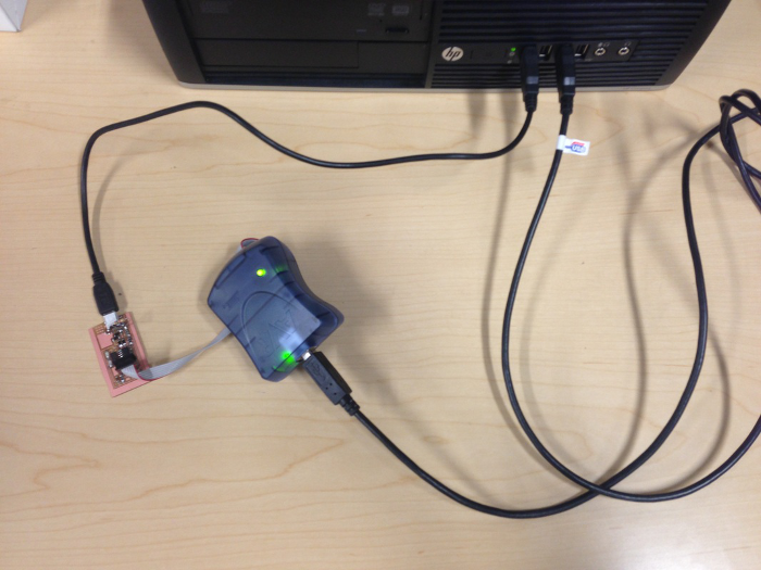
Final Workflow: Programming with Atmel Studio, using the hex file from the firmware folder First download the firmware.zip file found here: http://academy.cba.mit.edu/classes/electronics_production/index.html
Save firmware folder somewhere you will remember, like the desktop Atmel Studio Connect the FabISP's USB port to the computer via a USB cable. This will power the board. Connect the FabISP's 6-pin header to the AVRISPmkii, and connect the AVRISPmkii to the computer via the USB cable. New Project> GCC C Executable project Tools> Device Programming: [Tool: AVRISP mkii, Device: ATtiny44A, Interface: ISP] > Apply. >Target Voltage- Read (should be 5V) >Device Signature- Read >Memories- Click on the ellipses next to Flash and navigate to the firmware folder. Select the "main.hex" file. Then hit the 'Program' button. This should give you a "verified" message, so that you know the device has been properly programmed.
Another way I could have done this was to open the C file in the firmware folder and paste that into the command window. Then Build> Compile, and Build> Build Solution. This would generate the hex file.
References: http://academy.cba.mit.edu/content/tutorials/akf/programming_FabISP.html
Board is programmed! My last step was to remove the 0 ohm resistor and the solder jumper. To verify that the ISP works, on my PC, I went to: Start Menu > Hardware and Sound to check for the device