Computer Aided Design
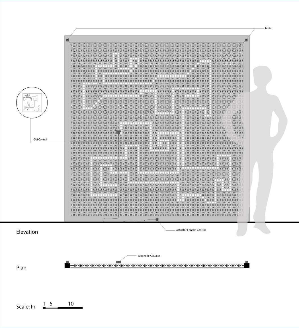
I began these drawings in AutoCAD, which is well suited for precise, technical drawings, more so than some other 2D programs. To create legibility, I imported this drawing into Adobe Illustrator to add lightweights. Illustrator has a very useful function called "select same" which allows you to select all objects that match a given object's style, whether that be color, fill, or line weight. I used this to select the different colors that I used in AutoCAD and convert them to all black lines with different weights. Of course, if your drawing imports with layers, you can just use the layers, but "select same" is a very handy tool for those times when you don't have separate layers.
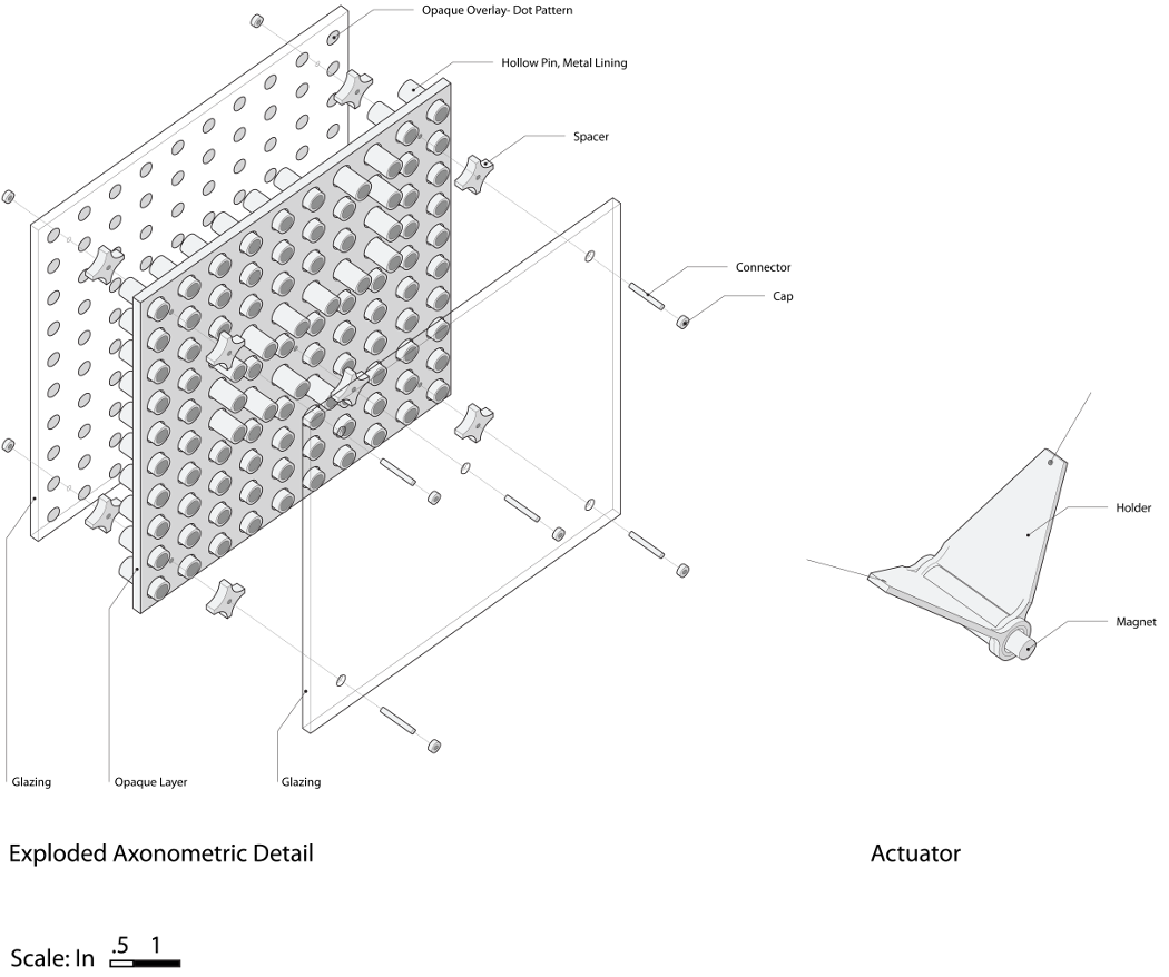
To build upon my previous drawings, I decided to revisit the "axonometric detail". I used this drawing to further explore details of the system, potential assembly strategies, and to better communicate my idea.
I began with a model in Rhino. Same basic components as last time: a "pin-press" layer in the middle, bounded by two layers of transparent material. On the back layer is a pattern of dots corresponding to the pins so that when pulled to the back, they are "closed" and when puled to the front, they are open.
This time, I decided to show the pins in different positions, to better convey the system's method of operation. I also modeled some additional details to begin thinking about an assembly strategy. I decided that this detail should represent one module of my system. Practically speaking, at the architectural scale, I will have to take into account the size limitations of materials, and a method of joining modules together. At the moment, there is no clear strategy for joining module to module. But as far as the modules themselves, I am thinking about creating "spacers" that sit on either face of the middle layer to properly space the translucent layers. In this scheme, threaded rod and bolts hold all of the layers together. So far it is a pretty straightforward system of assembly; however, I am not in love with the need for hardware- I will continue to explore how press-fit systems and tool-free assemblies might be applied.
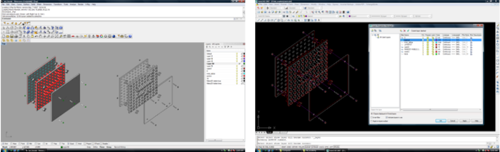
To create this drawing, I began with a Rhino model. I believe that it is MUCH more efficient to build a 3D model and use it to generate a drawing than just drawing a three-dimensional view, especially if you realize part way through that you want to shift some things around. I used the "Make2D" command in Rhino to make a 2D drawing of the current view of my 3D model. I then exported this as both a .dxf and opened it in AutoCAD, where I assigned the lines to different layers, getting it prepared for setting up lightweights in Illustrator. Relative to the other things I worked on for this week, I found that the layering process took a very long time. Many issues came up (as they always do!): lines generated in Rhino do not behave like lines in AutoCAD so many of the normally simple commands like "trim" do not work as they normally would and you have to find a work-around. Using the conventions that I learned in architecture school: 1. Outlines of objects, 2. Profiles, 3. Peak lines, 4. Valley lines, 5. Surface details. Unfortunately, this necessitates much line splitting because a single line can be a profile at one point and peak line at another point.
In order to add line-weights to the AutoCAD drawing, I decided to use Inkscape as a free alternative to Adobe Illustrator. From AutoCAD, I exported the drawing as both a .dxf and .ai file. Supposedly Inkscape can import both file types. However, there were issues with both and neither would open. I decided to plot to PDF, which opened without any issues. However, all of my layers were merged into one. After checking back to my plot settings, and a bit of searching online, I found no way to fix this issue in Inkscape.
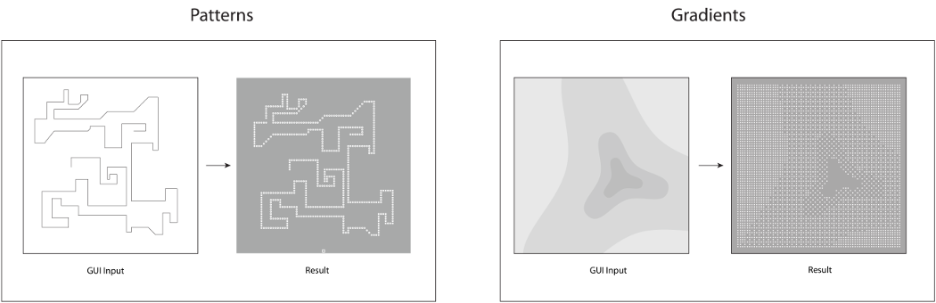
I created one last drawing to describe the system's operation. Graphic user input will be used to generate either lines or gradients.
Modeling & Rendering
For my project in particular, I believe that I should have a photo-realistic rendering to convey the lighting effects that I am trying to achieve. I used V-Ray for Rhino as my render engine. I first built my model in Rhino. I drew the front face of the middle layer first, then used Solids>Extrude Planar Curve to create a solid. I noticed that the surface has many subdivisions. Thinking back to this week's lecture, I wonder if this is because this geometry is being described as a surface as opposed to Boolean object? It did seem quite heavy and slow to work with. I only modeled the general overall structure (only openings, no pins). I purposely left out these details because I only wanted to convey the overall feel of the project and such small details would not influence this much. I could also tell that the model was already quite large and this would only make things much slower.
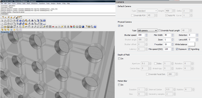
I started by adding a Sunlight system to my render. I find that this gives a good overall lighting effect. I used the settings shown below on the right, as I have found these to be good general settings for use in conjunction with a sunlight system. My process was to then do a series of test renders, trying to manipulate different settings in the rendering options dialogue box, and adjusting as I went along.
Pictured in the second thumbnail below is a diagram of my render "scene." I found the process of preparing my model for rendering to be somewhat like building a stage set. I added a secondary light behind the facade to reflect more light into the space. I created a floor and partitions around the screen to properly block or bounce light in the appropriate places. I even found it helpful to add some partitions on the "outside" of my scene to reflect more light into the space.
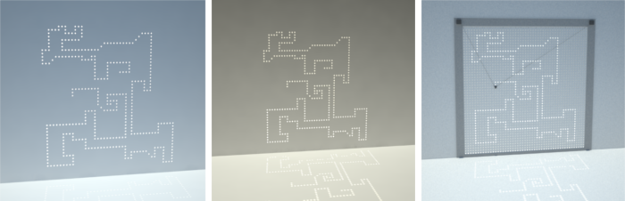
I began rendering using Irradiance Map as both my primary and secondary render engine. From my limited understanding of how this works, the Irradiance map algorithm calculates only the most "important" (detailed?) areas of global illumination in the scene, then fills in the rest by interpolation. It does a fairly accurate render and is relatively fast.
For the final render, I tried using Quasi Monte-Carlo as my secondary render engine. Again, this is my limited understanding explanation, but QMC does not use interpolation and gives a more accurate result. Though my scene is still very simple and sparse, I did find that the Quasi Monte-Carlo algorithm did give a "softer," more realistic looking render.
To finish the Render, I used Adobe Photoshop to add some figures to the scene.
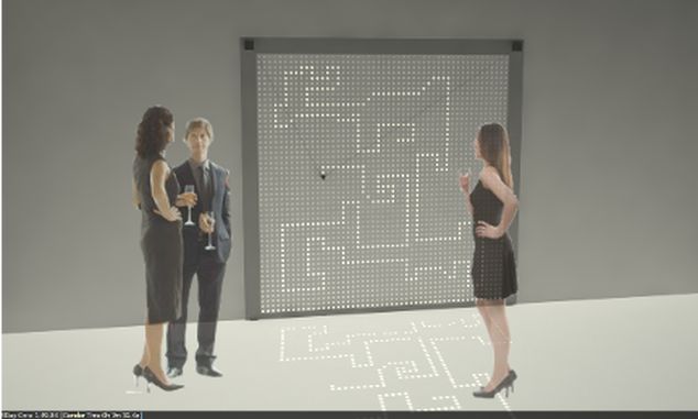 Photorealistic Render
 Testing various values, setting, and inputs for rendering.