Electronics Design
Stepper Motor Board + Arduino
For this assignment I designed a stepper motor driver board. I based it off of the "hello.stepper" board and modified it to be compatible with an Arduino. My first step was to continue researching stepper motors to better understand how the work. Below are some notes on steppers:
Study Guide: Stepper Motors
Two basic things to run a stepper:
1. Controller- generates step and direction signals (normally +/- 5V), controls 3 wires- STEP, DIR, GND (motion information)
2. Driver Circuit- generates current to drive the motor, controls 4 wires including power transistors. Sometimes it is possible to drive a small stepper directly from the controller and or controller and driver are combined in a single board.
If there are 4 wires, then it is a bipolar motor. If there are more it is unipolar. For unipolar, use ohmmeter to find the common ground wire for each half.
Transistors amplify the current to the stepper motor's coils
I am using the PF35T-48L4 stepper motor. Red and Green wires connect to battery supply.
References:
http://www.intorobotics.com/tutorials-and-resources-to-control-stepper-motor-with-arduino-board/ https://learn.adafruit.com/adafruit-arduino-lesson-16-stepper-motors/overview http://people.ece.cornell.edu/land/courses/ece4760/FinalProjects/s2007/jxd2/djd36_jxd2/neuralrobot.htm http://arduino-info.wikispaces.com/SmallSteppers#1turn http://arduino.cc/en/Tutorial/StepperUnipolar http://www.schmalzhaus.com/BigEasyDriver/https://www.sparkfun.com/tutorials/400 Arduino Stepper Tutorial: http://www.azega.com/controlling-a-stepper-motor-with-an-arduino/
Design & Production
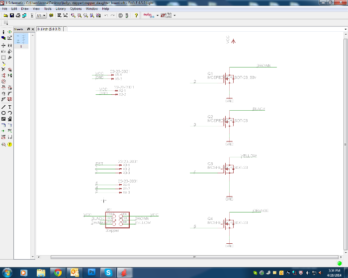
I then moved on to design. I used Eagle to design the circuit. I found this tutorial from Jeremy Blum extremely helpful: https://www.youtube.com/watch?v=1AXwjZoyNno
I downloaded the fab library (fab.lbr) found here: http://academy.cba.mit.edu/classes/electronics_design/index.html
One of the most useful tools that I learned was the "group" tool which allows you to select multiple components and connections. After selecting the items, right click and select Move: Group.
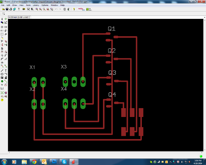
I decided that I could make a very simple design with only transistors and pads to connect to the motor, main board, and a power supply. After adding these components, I exported a png file for fabrication.
X
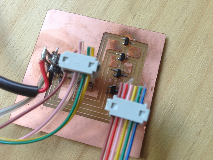
I initially found that some of the traces were slightly too close together, and so I edited the png in Photoshop to allow for enough space in between the lines. After a few attempts at milling, I finally made a good board.
Stepper Motor Driver Schematic and Board Files available here
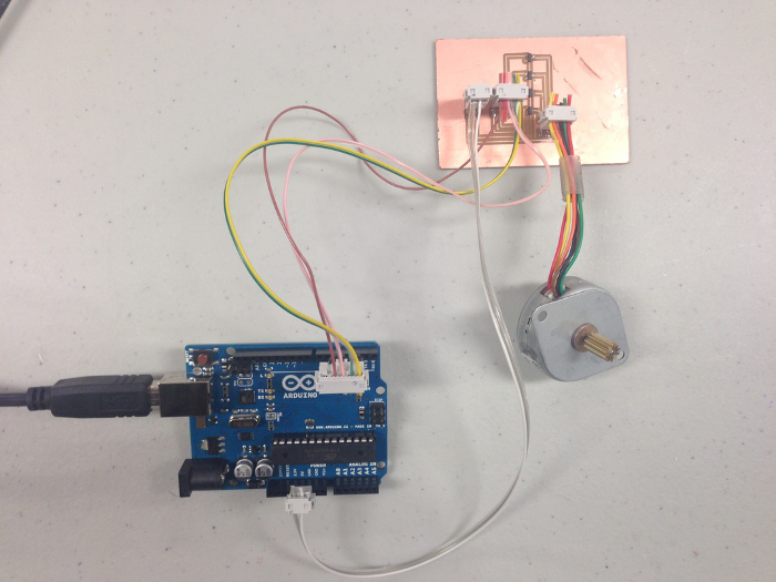
I connected pins 2,3,4,5 of the Eduino to the jumpers on the driver board. I then connected the GND and V on the driver board to a 12V power supply, and connected the GND on the board to the GND on the Arduino. Lastly, I connected the driver board to the motor.
Programming & Running the Stepper Motor
Tools> Board> Arduino Uno
Serial Port> usually one of the last ones that does not say "bluetooth"
Here is my code that I used to check if the board is working:
#include <Stepper.h>
// change this to the number of steps on your motor
#define STEPS 24
// create an instance of the stepper class, specifying
// the number of steps of the motor and the pins it's
// attached to
Stepper stepper(STEPS, 2, 3, 4, 5);
void setup()
{
// Initialize random number generator
randomSeed(analogRead(5));
}
void loop()
{
// Pick a random direction and distance to move
int rand = random(-10, 10);
// Pick a random speed
int spd = random(5, 20);
// Go
stepper.setSpeed(spd);
stepper.step(rand);
delay(1000);
}
* This code is based off of the tutorials found here: http://www.azega.com/controlling-a-stepper-motor-with-an-arduino/ http://arduino.cc/en/Tutorial/MotorKnob
I began to play around with the code to better understand how to control the motor. I changed the void loop code as follows:
void setup()
{
// set the speed of the motor in RPMs
stepper.setSpeed(10);
}
This quickened the speed of rotation, and also changed it from a random range of values to a constant number.
I changed this section of the code:
void loop()
{
// move a number of steps
stepper.step(5);
}
This turned the motor in a continuous circle. Based on other code examples, I guessed that what was happening was that the motor was turning by five steps repeatedly, so it gave the appearance of continuous rotation.
So I decided to try adding a delay:
void loop()
{
// move a number of steps
stepper.step(5);
delay(1000);
}
The motor now turns for five steps, then delays for 1000 pulses (I am guessing), and continuously repeats this cycle.
Lastly, I wanted the stepper to run continuously back and fourth. I edited the code as follows:
void loop()
{
// move a number of steps
stepper.step(5);
delay(1000);
// move a number of steps
stepper.step(-5);
delay(1000);
}
The stepper now runs forward, pauses, then runs back, pauses again, and repeats the cycle. Very exciting!