


final project
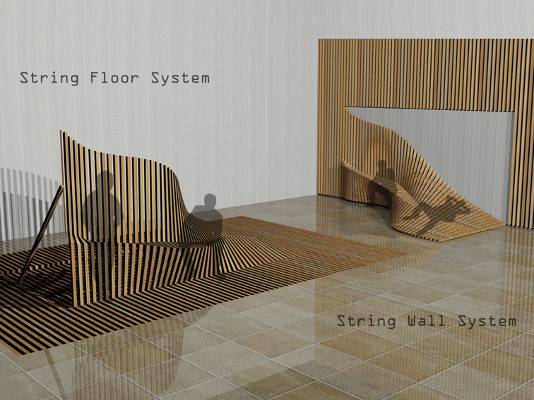
My first concept was to create a wall system able to change shape from a vertical surface in a sort of sculptural wave (with the ability to create different seating positions).
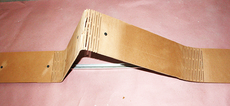
For my final project, I made a single element able to change shape from vertical to a zig zag shape (seating section).
I can use the single element as part of a multiple series (such as in the initial plan) or such as driving element for a panel attached to it.
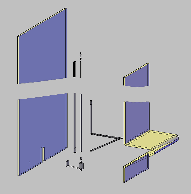
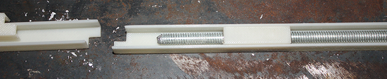
The movable element is composed of two U aluminum channels one inside the other one.
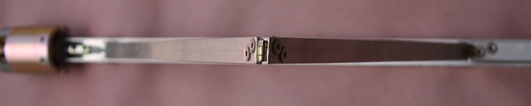
One of them is divided in three pieces connected with a hinge. Inside the channels there is a 1/4 threaded rod connected to a 12V high speed DC motor with a coupler.
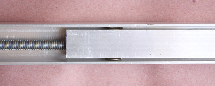
One squared threaded piece is connected to the inside channel.
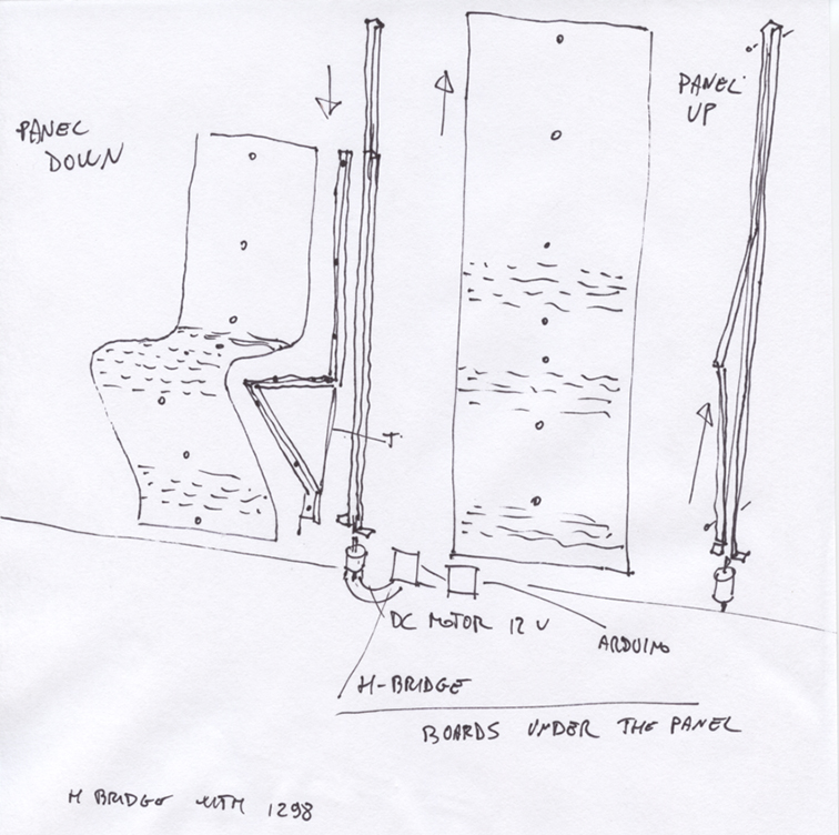
When a capacitive sensor under the plywood or cardboard panel turns the motor (controlled by a fabduino board + H-bridge, the rod turns and the channel move up and down changing shape.
what I did
I started with sketching my idea and putting down all the elements I needed.
After, I designed the frame and connections with motors.The idea was to create the sliding element small enough to use it as single element or driving element for the panel.
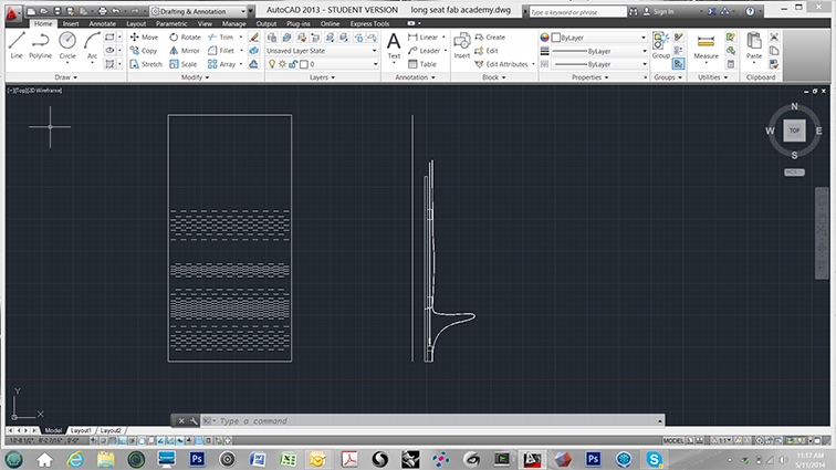
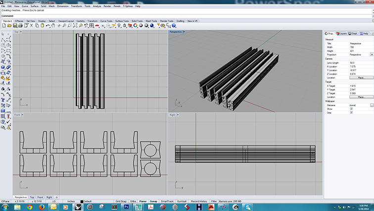
Here you can find the dwg file for the frame, and here the one for the sliding rail.
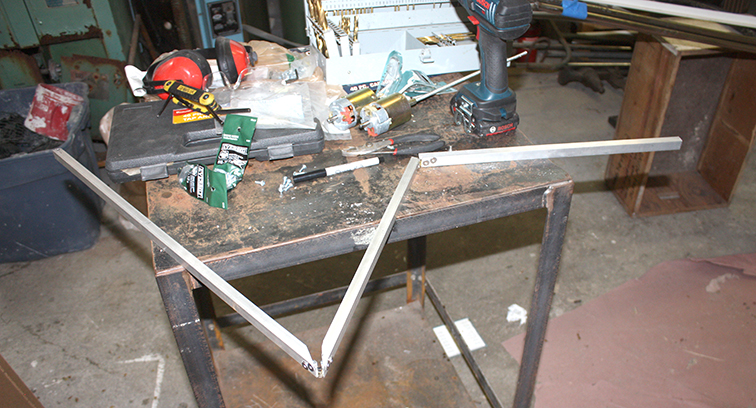
The construction of the frame was really difficult.
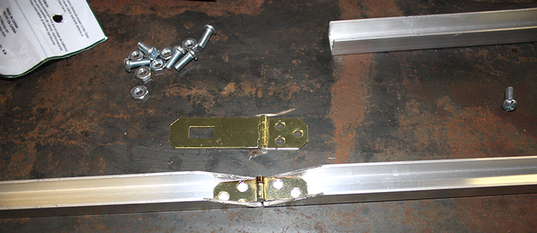
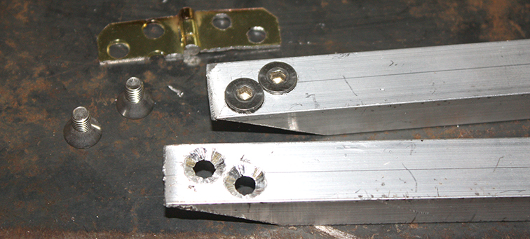
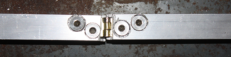
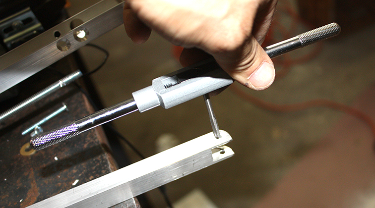
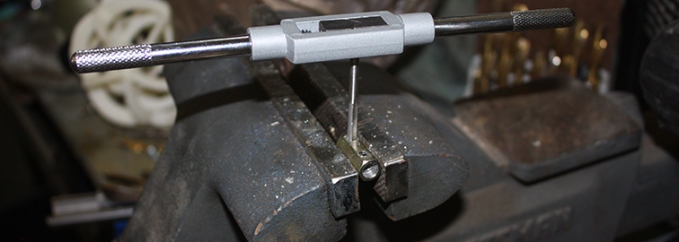
I modified hinges I bought from Home Depot. I bought a "tap and die set" and I "tapped" almost all the holes to avoid the use of nuts.
And finally the frame was done with all the connections, washers, nuts and screws.
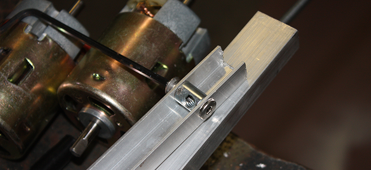
After building the frame I worked on the connection with the motor to the structure and to the 1/4 threaded rod with the coupling.
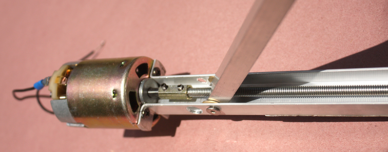
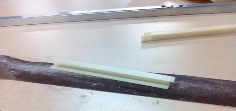
The 3D printed sliding rail was perfect and was sliding smootly inside the U channel. I used brass washer to help the movement and compensate the space between the two U channels.
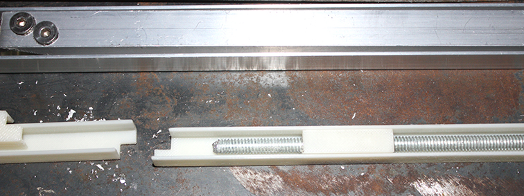
Before to connect the motor I tried the movement rotating the rod with a electrical drill and it worked.
I started to design the H-bridge for my Fabduino board (still in construction...) to test it. The idea is to make the motor starts when the capacitive sensor under the plywood or cardboard panel enter in contact with the human body.
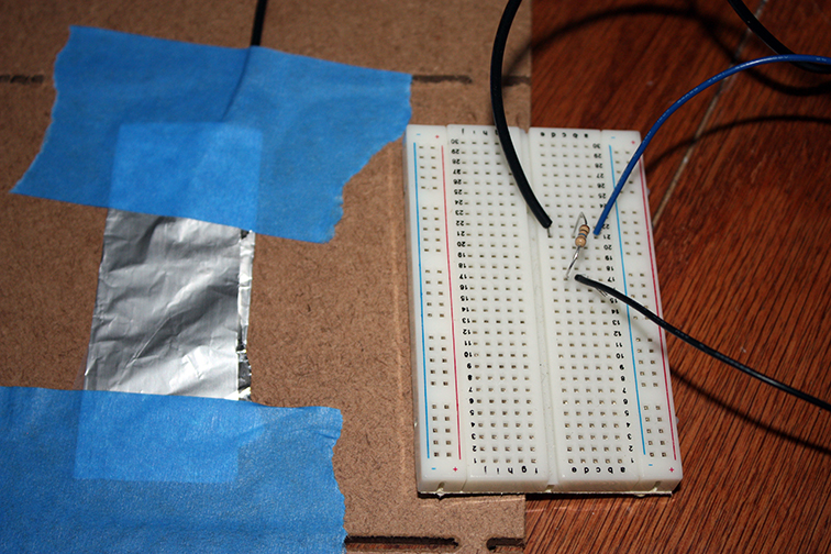
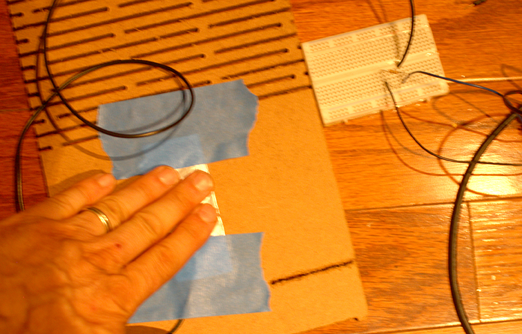
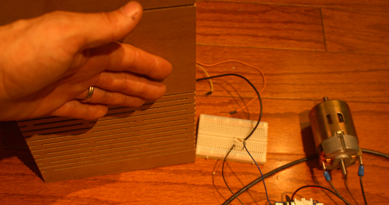
The capacitive sensor can sense the electrical capacitance of the human body. I used a simple aluminum foil at the end of a wire and a 10M resistor between the sensor and Arduino. The sensor will start to sense a hand or body inches away from the sensor and you don't need to touch it. My idea is to set the sensor so it can activate the motor around 4/5 inches from the board. The motor will unfold the panel. "The capacitiveSensor method toggles a microcontroller send pin to a new state and then waits for the receive pin to change to the same state as the send pin" and you can find more information here.
My initial idea was to make two sliding elements moved by two DC motors controlled by Fabduino board.
I started studying the L298 (multiwatt 15) circuit and its pin connections.
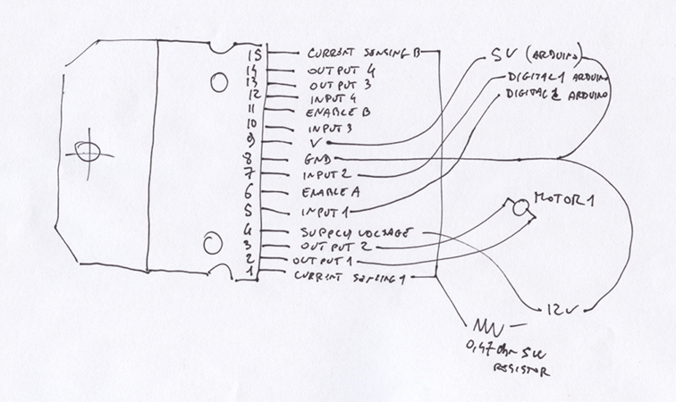
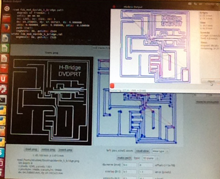
I designed with eagle a dual H-Bridge using an l298 circuit to move the two 12V DC motors.
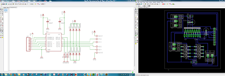
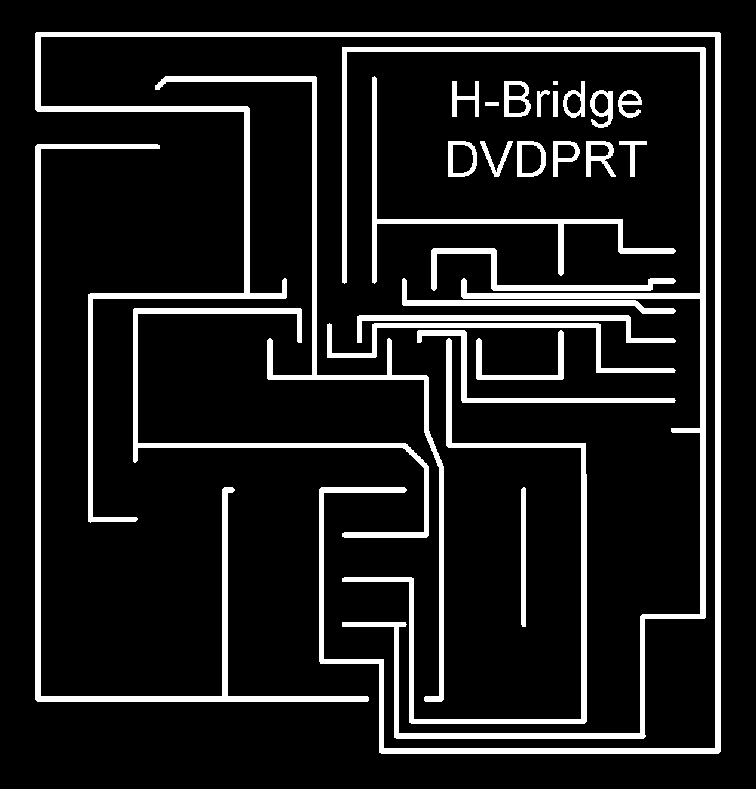
Here you can download the Eagle schematic and here the board.
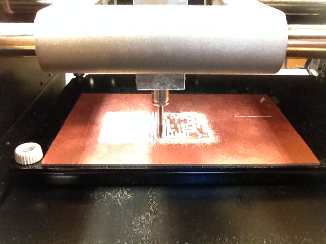
I milled with Modela the board.
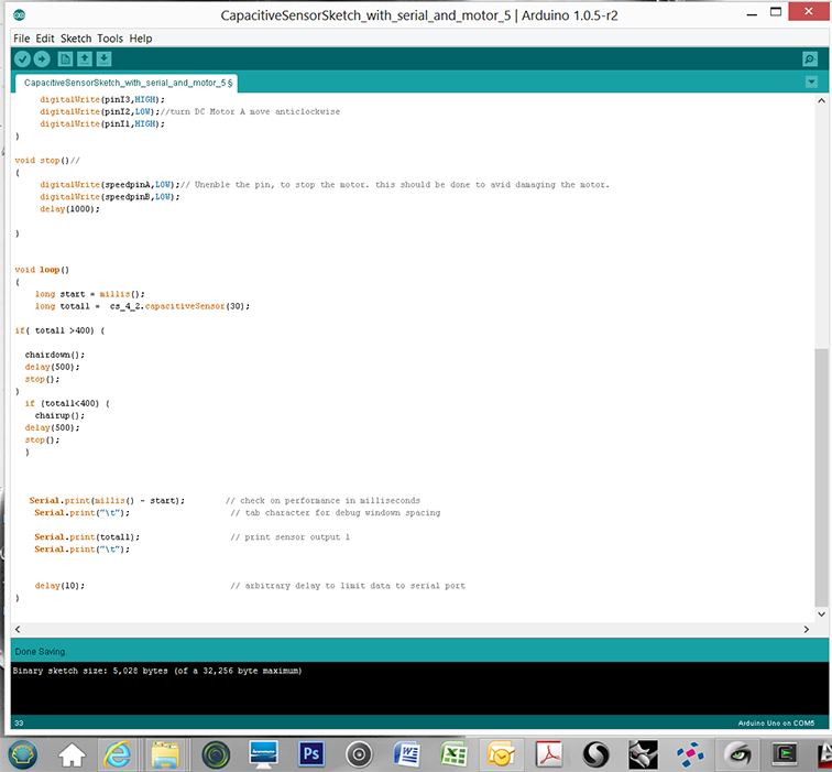
Meanwhile, I was waiting for the components, I started to write the code in Arduino IDE to test the capacitive sensor and the motor.
After several tests, using the Arduino IDE Serial Monitor, I figured out that the best value to switch my motor using the capacitive sensor I made was 400 (with the body close 3" more or less).
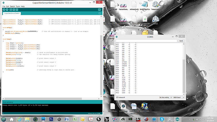
I incorporated the code for the capacitive sensor with the one to controll the two motors.
Here you can download the Arduino code.
The most difficult part was to figure out the delay value. I started checking from 500 and going up until the number of rotations was perfect with the movement.
I 3D printed in ABS with an Uprint the sliding rails for the inside part of the U channel.
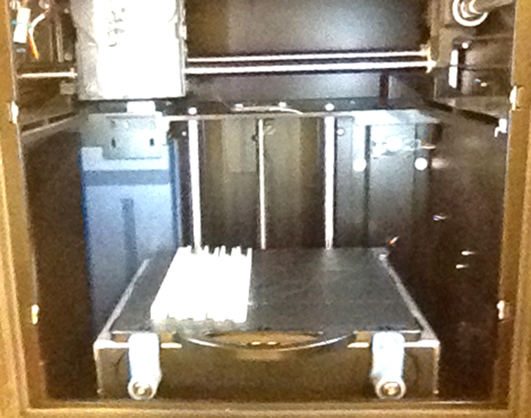
I had to sand the side of the rail to make it slide smootly.
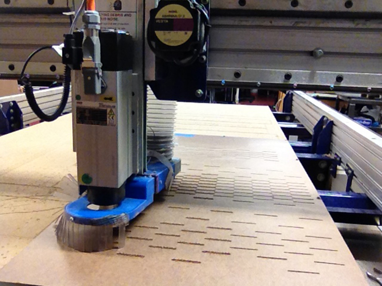
I started working on the panel and I milled with the Shopbot all the cuts to make more flexible the cardboard.
I didn't have all the components I was expecting to use, but I tried to build the board with the stuff I had.


Ready to test it!
arduino code
#include <CapacitiveSensor.h> //download and install capacitivesensor library from Arduino website
CapacitiveSensor cs_4_2 = CapacitiveSensor(4,2); // 10M resistor between pins 4 & 2, pin 2 is sensor pin, add a wire and or foil if desired
int pinI1=8;//define I1 interface
int pinI2=11;//define I2 interface
int speedpinA=9;//enable motor A
int pinI3=12;//define I3 interface
int pinI4=13;//define I4 interface
int speedpinB=10;//enable motor B
int spead =127;//define the spead of motor
void setup()
{
cs_4_2.set_CS_AutocaL_Millis(0xFFFFFFFF); // turn off autocalibrate on channel 1 - just as an example
Serial.begin(9600);
pinMode(pinI1,OUTPUT);
pinMode(pinI2,OUTPUT);
pinMode(speedpinA,OUTPUT);
pinMode(pinI3,OUTPUT);
pinMode(pinI4,OUTPUT);
pinMode(speedpinB,OUTPUT);
}
void chairup()
{
analogWrite(speedpinA,spead);//input a simulation value to set the speed
analogWrite(speedpinB,spead);
digitalWrite(pinI4,HIGH);//turn DC Motor B move clockwise
digitalWrite(pinI3,LOW);
digitalWrite(pinI2,HIGH);//turn DC Motor A move clockwise
digitalWrite(pinI1,LOW);
}
void chairdown()//
{
analogWrite(speedpinA,spead);//input a simulation value to set the speed
analogWrite(speedpinB,spead);
digitalWrite(pinI4,LOW);//turn DC Motor B move anticlockwise
digitalWrite(pinI3,HIGH);
digitalWrite(pinI2,LOW);//turn DC Motor A move anticlockwise
digitalWrite(pinI1,HIGH);
}
void stop()//
{
digitalWrite(speedpinA,LOW);// Unenble the pin, to stop the motor. this should be done to avid damaging the motor.
digitalWrite(speedpinB,LOW);
delay(1000);
}
void loop()
{
long start = millis();
long total1 = cs_4_2.capacitiveSensor(30);
if( total1 >400) {
chairdown();
delay(48000); //it is based on the lenght of the folding element
stop();
}
if (total1<400) {
chairup();
delay(48000);
stop();
}
Serial.print(millis() - start); // check on performance in milliseconds
Serial.print("\t"); // tab character for debug windown spacing
Serial.print(total1); // print sensor output 1
Serial.print("\t");
delay(10); // arbitrary delay to limit data to serial port
}
What it does
The movable structure I made can be used as single part like in my first idea, or as support for a movable panel. We can have a wall system that become a seating system only when someone needs to seat. Thanks the capacitive sensor, the wall system starts to come down only when someone touch the wall or lean to it and slowly enough to give the person the time to adjust his / her position.
what worked and what didn't
A lot of thing did't go as I was expecting....
First, with all the tests I did to try the movements and set the right speed, etc. the cardboard started to crack.

I was expecting it, but it started only after a couple of days. I was using the cardboard only as a test. I am thinking to use a more flexible and stroger colored acrylic sheet. It is very expensive and it can be a good choice for production and not for testing.
Second, I spent a lot of time to design and print the inside movement in ABS.
I tested it with a electric drill and it was working, but when I tested it with the 12V motor it didn't move. I had to change it with a simple threaded connector made of a cross downel nut .
Third, I was expecting the threaded rod strong enough to rotate without any problem....the noise is terrible, because it is touching the side of the U channel ....solution is to make it rotate inside some nylon washers blocked on the U channel.
At the end I think it will be cheaper to make the frame in steel (cheaper and stronger) even because the additional weight is not a problem (the tension on the panel will help to push up the frame.
what I learned
Even if I tried to plan everything, I had to change design several time during the development of the final model.
In addition of what I learned during the course, I had to study different things. I did more practice in programming with Arduino, I created the H-Bridge, the capacitive sensor.
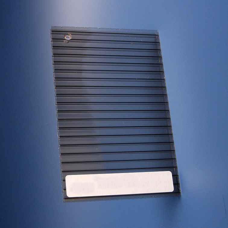
I studied different materials for the frontal board and I think the best solution is the polycarbonate. I can find polycarbonate made with different colors and in different thickness. It is tough and impact resistant material. It is light weight with a nice clarity. In this project safety and security is really important. It will not shrink with age, only with temperature. It is also resistant to coffee, beer, wine and other common liquids.
LEXAN 48 in. x 96 in. x .118 in. Clear Polycarbonate Sheet from home depot costs $167.
With time (and money) can be interesting also to test the polycarbonate twinwall (only in horizontal way). The cost of it is around $70.00 for a sheet 48" x 96".
I think it will curve easily without breaking.
bill of materials
Probably, during the realization of the model I spent more than $200 in tests with different metal profiles, pressboards, motors, connectors, etc.
For the final project I can create a module 4' x 8' with the following materials:
1x 3/16 in. x 48 in. x 8 ft. Tempered Hard Board $14.35
1x Everbilt 3/4 in. W x 9/16 in. H x 96 in. L Aluminum C-Channel with 1/16 in. Thick $10.97
1x 1/2 in. W x 1/2 in. H x 96 in. L Aluminum C-Channel with 1/16 in. Thick $9.39
2x Everbilt 3/4 in. x 2-7/64 in. Satin Nickel Decorative Hasp $2.27
1x Crown Bolt M4-0.7 x 6 mm Plain Steel Metric Socket Set Screw (2-Piece per Pack) $0.52
3x screw #6-32 tpi x 1 in. Stainless-Steel Flat-Head Stainless-Steel Socket Cap Screw (2-Piece) $1.28
2x 3308 RPM DC Motor $9.95
3308 RPM DC Motor
2x FR1 (4x6 + sacrifical one) $0.25
2x AK300/3 connector terminal block $0.51
8x Header $0.46
1x L298N $4.67
8x 1N4001 Diode $0.027
2x 100nF (0.1 uF) capacitor $ 0.84
2x 0,47Ohm x 1W Resistor $0.37
3D Printed channel $30.00 or cross downel nut $1.00
1x Arduino or Compatible such as Fabduino from $4.00 to $20.00
TOTAL: $ 66.20