


About the assignment: output devices
Add an output device to a microcontroller board you've designed and program it to do something.
what I am learning
Stepper motors, MOSFETs.
How to design a board to use a stepper motor (based on Neil's board).
How to program a board modifing Neil's code hello.stepper.bipolar.44.cad.
How to make my own Arduino Board in various Fab versions (hello.arduino, fabkit2.0/fabduino, barduino)
How to control stepper motor with arduino board.
design the board
For this assignment I designed a board for my final project (I will create a model for a movable sculpture. I will need to move up and down a single elements with a step motor. To drive a motor I need to create a board with a controller (Attiny44a) and MOSFETs. The metal–oxide–semiconductor field-effect transistor practically is a switch that can be driven by applying a voltage to one of its three pins (called gate). Each MOSFET has a Gate, a source and a drain (flange). If there is not positive voltage applied between the gate and the source the MOSFET is not conducting.
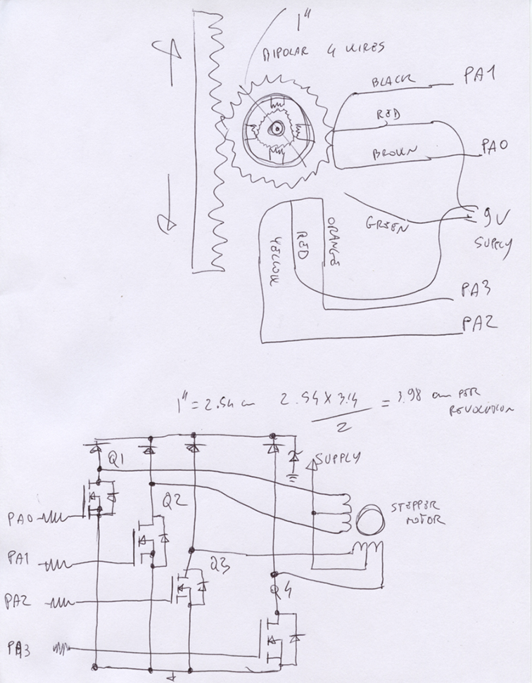
The stepper motor consist of a stator an a rotor. The rotor carries a set of permanent magnets, and the stator has the coils. There are four coils (90 angle between each other) and they are activated in a ciclic order. It divides a full rotation into a number of equal steps and we can control the position (move and hold) of these steps without any feedback sensor.
There are different driving modes: Wave drive (only one coil is energized each time), Full step drive (the coils are energized in pairs so the motor will need double of the voltage), Half Stepping (all coil pairs can be energized simultaneously, causing the rotor to rotate half the way as a normal step), microstepping (power the coils with a waveform, in this way, the positioning from one step to the other is smoother).
For my assignment I will use an unipolar stepper motor. It has 6 wires (four for the out pin and two for the power input). It moves at 7.5 degrees/step with one step at time and it draws 500mA. I will need to calcolate the speed and movement (up / down) based on the diameter of my gear. 360/7.5 gives me 48 steps every revolution. If I use a gear of 1" diameter (2.54 cm) I will have 2.54 cm*pi/2)= 3.98 cm per revolution....too much. I am going to create a smaller model so I think I will use the gear on the motor. 1/4"*2.54 * pi/2= 0.99cm per revolution.
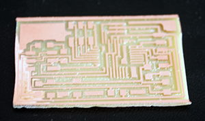
I designed my schematic using Eagle.
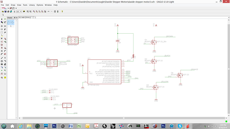
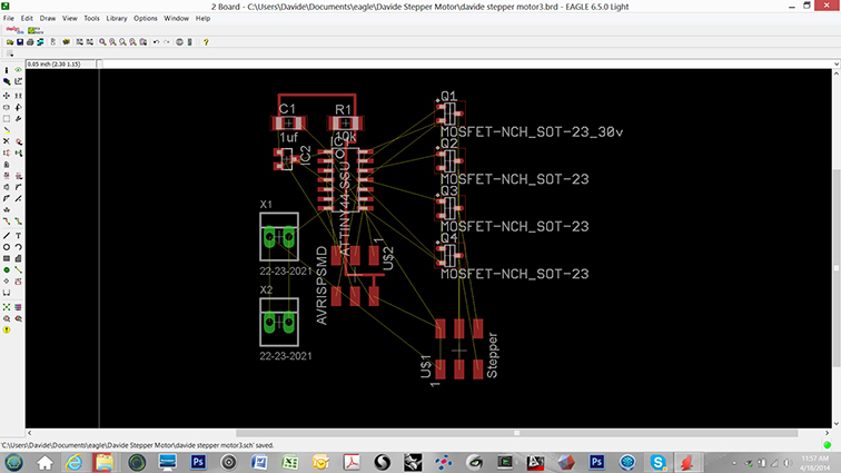
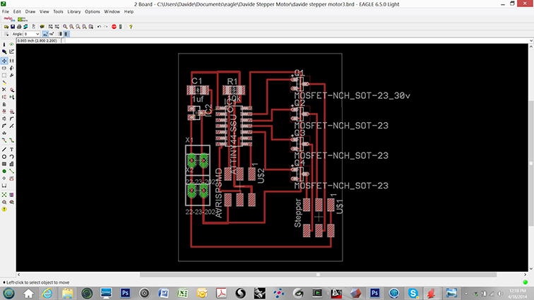
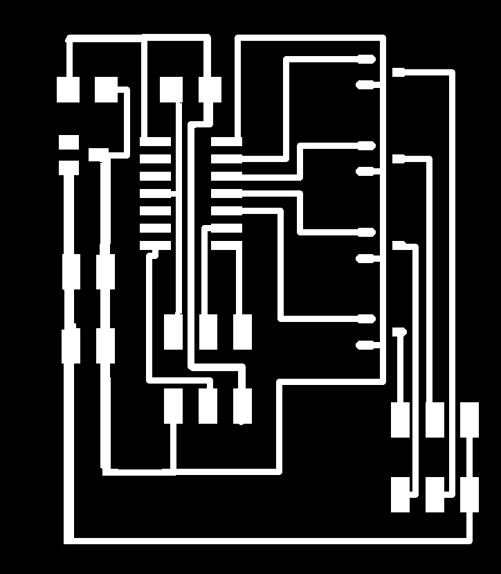
I made a couple of mistakes (some of the lines were too close) and I fixed that with Photoshop.
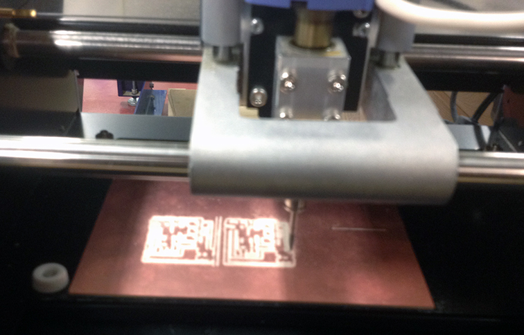
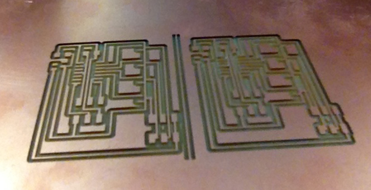
I made a couple of them to have a spare one.
Ready for the programming.
program the board
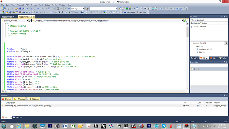
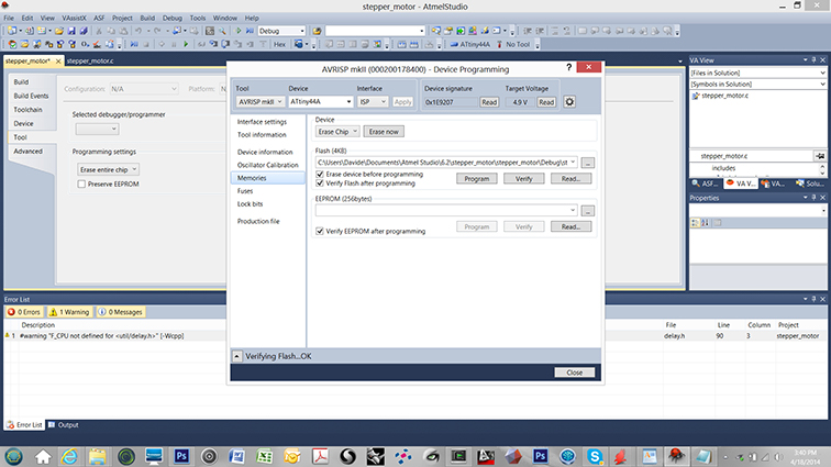
I used Atmel studio to program it and I modified Neil's code hello.stepper.bipolar.44.cad.
I checked the connections between my motor (PF35T-48L4)and the ports following the wiring schematics
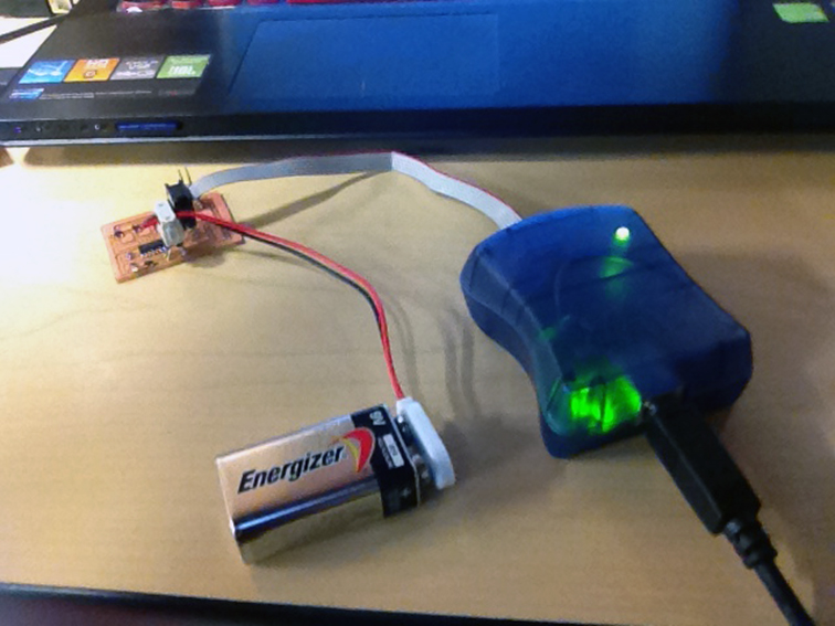
Final result
At the first attempt the motor was running, now I have to play a little bit with the parameters...
stepper motor 3 from Davide Prete on Vimeo.
stepper motor with arduino
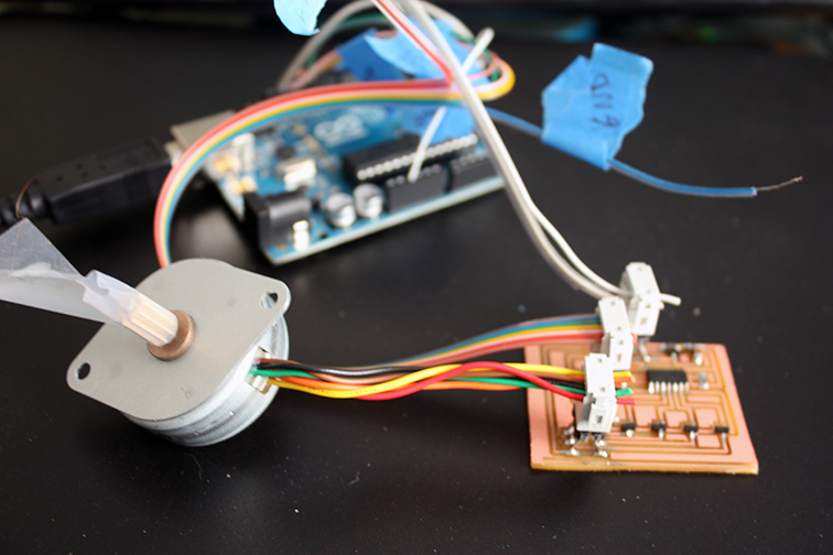
In the same motor I used before (PF35T-48L4) I have the red and green wires connected to the power and the orange and black to one coil and brown and yellow to the second one.
I am following this tutorial to connect the arduino and program my board.
- Connect the ATtiny84/44 Pin 1 (with the little dot) to the 5 volt breadboard rail.
- Connect the ATtiny84/44 Pin 14 to ground.
- RESET: Connect the ATtiny84/44 Pin 4 (Reset) to Arduino Pin 10.
- MOSI: Connect the ATtiny84/44 Pin 7 to Arduino Pin 11.
- MISO: Connect the ATtiny84/44 Pin 8 to Arduino Pin 12.
- CLOCK: Connect the ATTiny84/44 Pin 9 to Arduino Pin 13
- Connect the ground and 5v from the Arduino to the breadboard.
I am still working in collecting all the components for my fabduino, so for now I will use an Arduino board I have.
I am going to use a simple code to make to motor spin in one direction.
int motorPin1 = 13;
int motorPin2 = 12;
int motorPin3 = 11;
int motorPin4 = 10;
int delayTime = 500;
void setup() {
pinMode(motorPin1, OUTPUT);
pinMode(motorPin2, OUTPUT);
pinMode(motorPin3, OUTPUT);
pinMode(motorPin4, OUTPUT);
}
void loop() {
digitalWrite(motorPin1, HIGH);
digitalWrite(motorPin2, LOW);
digitalWrite(motorPin3, LOW);
digitalWrite(motorPin4, LOW);
delay(delayTime);
digitalWrite(motorPin1, LOW);
digitalWrite(motorPin2, HIGH);
digitalWrite(motorPin3, LOW);
digitalWrite(motorPin4, LOW);
delay(delayTime);
digitalWrite(motorPin1, LOW);
digitalWrite(motorPin2, LOW);
digitalWrite(motorPin3, HIGH);
digitalWrite(motorPin4, LOW);
delay(delayTime);
digitalWrite(motorPin1, LOW);
digitalWrite(motorPin2, LOW);
digitalWrite(motorPin3, LOW);
digitalWrite(motorPin4, HIGH);
delay(delayTime); }
I am using arduino IDE only to program my board.
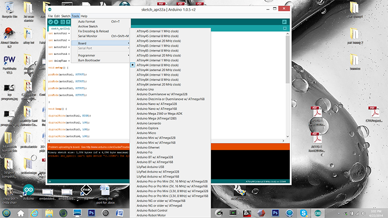
Open the Arduino IDE and go to “Tools” -> “Board” and select the option “ATTiny44 (internal 8 MHz clock)”.
Go to “Tools” again and select the option “Burn Bootloader”.
You should see a message saying “Done burning bootloader.”