

About the assignment: networking and communications
Design and build a wired &/or wireless network connecting at least two nodes
milling The boards
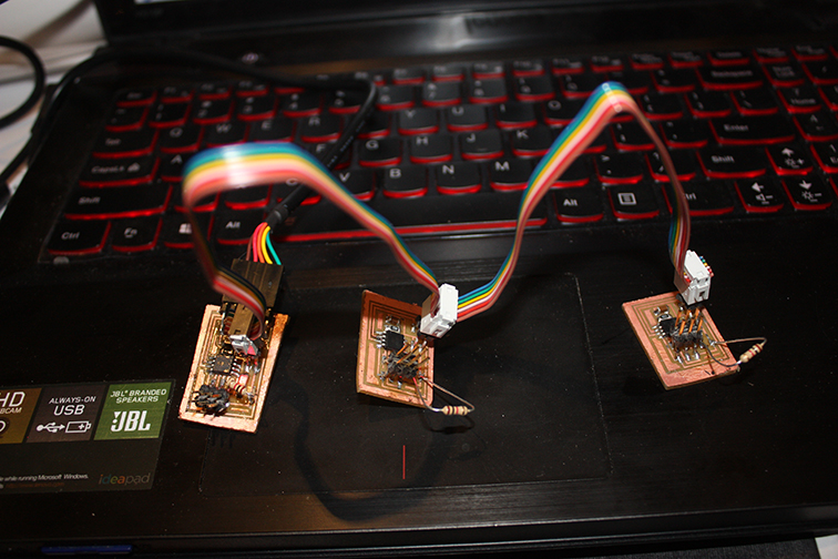
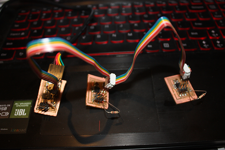
This week's assignment is to create a wired or wireless network of boards with a minimum of two nodes. I started from Neil's files of hello.bus.45 board to mill and build 2 nodes and one bridge. The bridge board is connected to the computer through the FTDI wire and bridge and two nodes are connected trough the six pin connector.
I milled the two nodes and one bridge plus one extra each (to be sure) and I solder all the components.
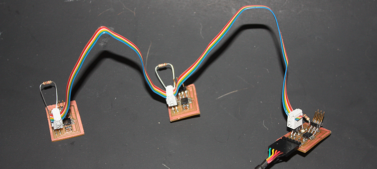
The bridge board (the only one that it can be connected to the computer through an FTDI cable) and to the two nodes have only one difference that is the FTDI connector.
C Code
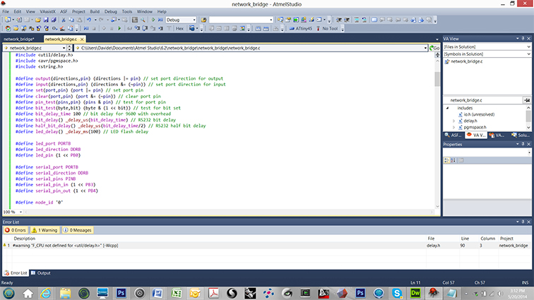
I modified the c code that Neil provided so each node has its own identification, "node 0" for the bridge and "node 1" and 'node 2" for the nodes.
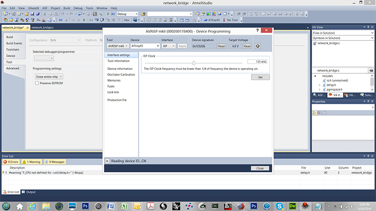
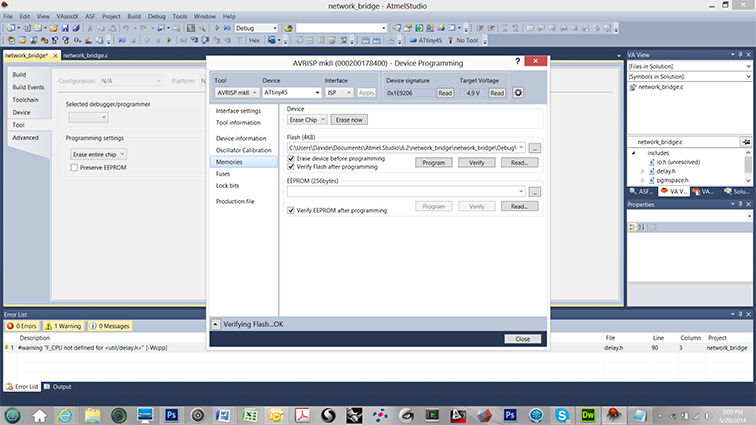
Program the board and arduino ide
To program the boards I used Atmel Studio using the C code I modified before. The first board was the bridge and I use in the C code line "define node_id '0' ". For the second and third boards (two nodes) I used in the C code line "define node_id '1' " and "define node_id '2' ".
I used Arduino IDE to talk to the network. I connected the network to my computer using the bridge board and a FTDI cable. I opened Arduino IDE and I changed value to 9600 baud on Serial Monitor (Tools in Menu) Changing the number trough serial monitor the leds light up. Here are nodes in action: