THE FAB ACADEMY 2014
CIRO MEJIA ELIAS

THE FAB ACADEMY 2014
|
|
|
Electronics Production
The procedure was as follows: - Place adhesive double-sided tape on the back of the plate. - Adhere to the table of the machine " MODEL " , taking into account the marks of this table. - Press "VIEW" tool to locate the source. 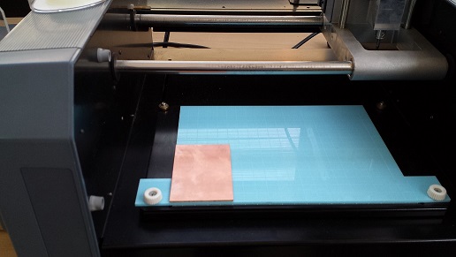 - Press " Make.path " to make the settings . - Press " View.path " to visualize work. - Press " Make.rml " to start milling. 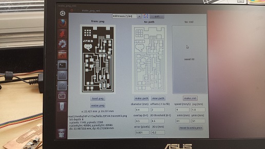 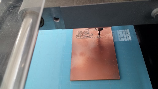 - Finish the job by removing the plate from the machine with a spatula . 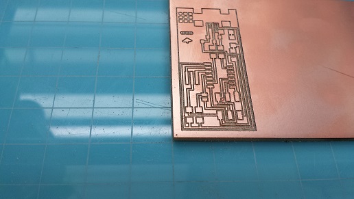 Cutting excess plaque done with care, a shear is suggested and then file it.
In this step the assembly of electronic components based on plate welding was performed. It was difficult to finish this step, because it takes practice to be able to weld without breaking the tracks and leave a good finish. The following is suggested: - Practicing in another plate to acquire skill. - Working with a lens adjustment - Fill the contact plate welding. - First place the soldering pencil on the contact to take the right temperature for the union and then placed on the tin, this will slide on contact. - With a clip lead component in the desired location with the pencil and make union playing component and solder deposited on contact. Mounted components are shown: 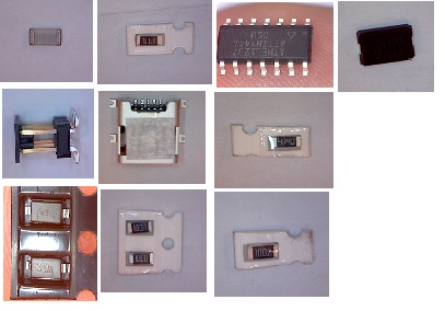 Below welded end plate is shown. 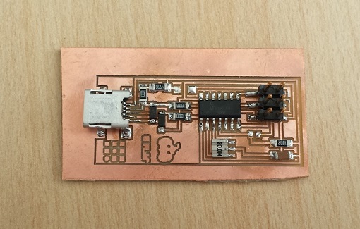 After welding verify that there is continuity in the plate using a multitester I had to make two plates because the first track is broke, try placing a bridge but also was broken. In the second plate I had no connection between my board and the PC to install the firmware via USB, this was due to the microcontroller was not welded properly one of the pins not making contact. I went back to welding and finally step program. 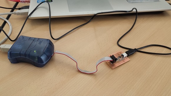 - sudo apt-get install flex byacc bison gcc libusb-dev avrdude - sudo apt-get install gcc-avr - sudo apt-get install avr-libc - sudo apt-get install libc6-dev Download the Firmware: - wget http://academy.cba.mit.edu/classes/embedded_programming/firmware.zip - unzip firmware.zip 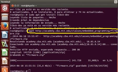 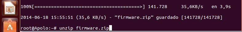 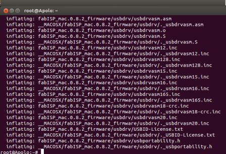 Programming the ISP: - sudo make fuse 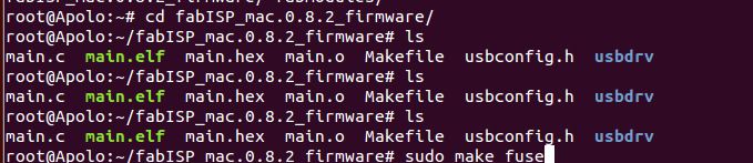 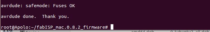 - sudo make program 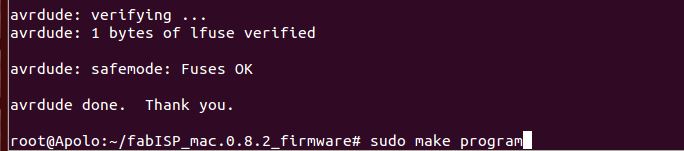 |