THE FAB ACADEMY 2014
CIRO MEJIA ELIAS

THE FAB ACADEMY 2014
|
|
|
Output Devices This assignment is to add an output device to a circuit board that has been designed and program it to do something. To this task choose to work with two output devices: DC Motor and Servo Motor. The work was divided into three stages a) Milling board. We worked with the milling parameters from previous assignments. The files for the layout of the board were obtained from the website of the academy. DC Motor: 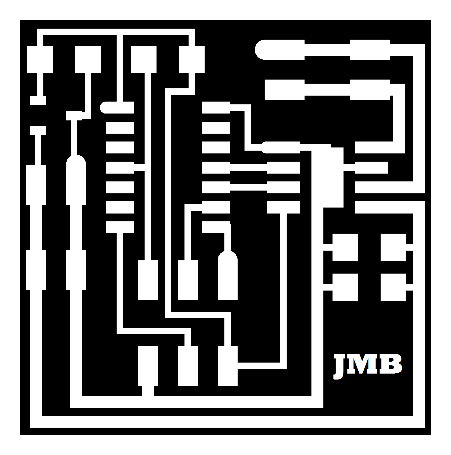 Servomotor (According the trace can connect two servos):  b) Installation of electronic components to the board. To weld the components was based on the distribution found in the page of the academy.
DC Motor 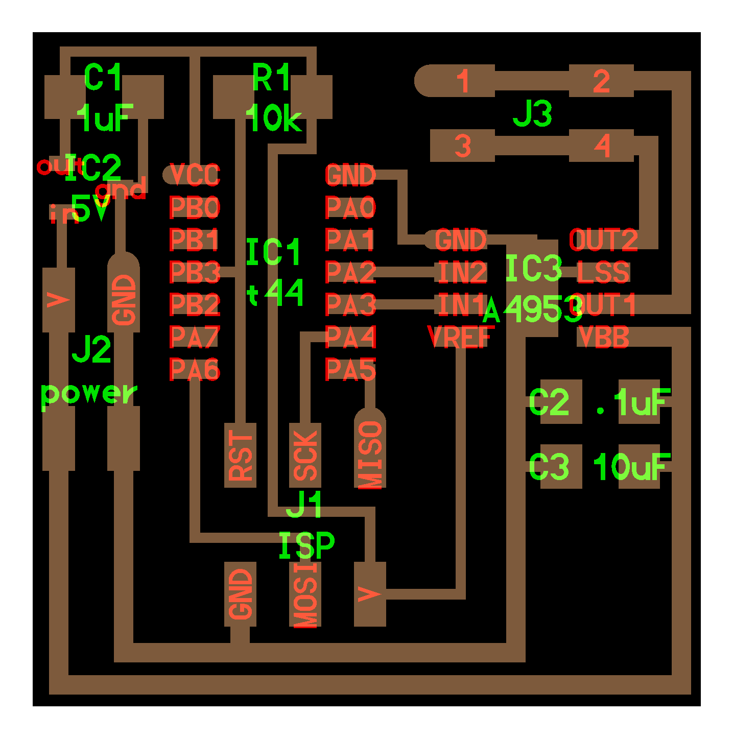 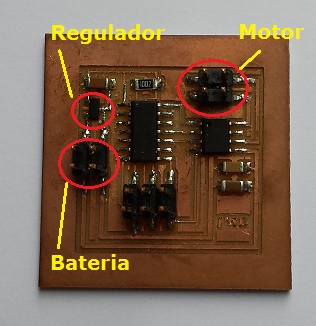 Servomotor 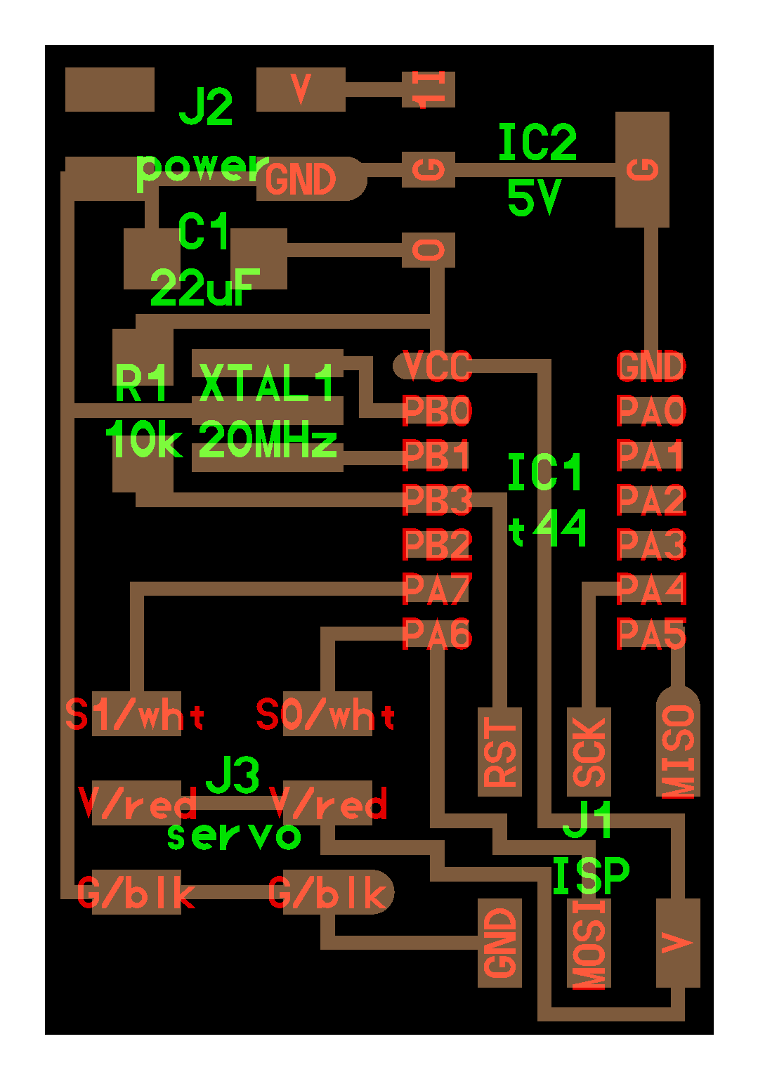  c) Configuration, connection and testing of the device. DC Motor. 9V battery is connected to the plate, mounted regulator causes the voltage is regulated to 5V to power the system. A DC motor has only two outputs VCC and GND. If we reverse the direction of rotation only change polarity. For configuration connect the ISP programmer to the board and the 9V battery. 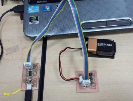 Then unload the C and Makefile Motor Academy page files and digitamos Ubuntu terminal (located in the download directory): sudo make -f hello.H-bridge.44.DC.make For testing the ISP is disconnected and the motor is connected to J3. 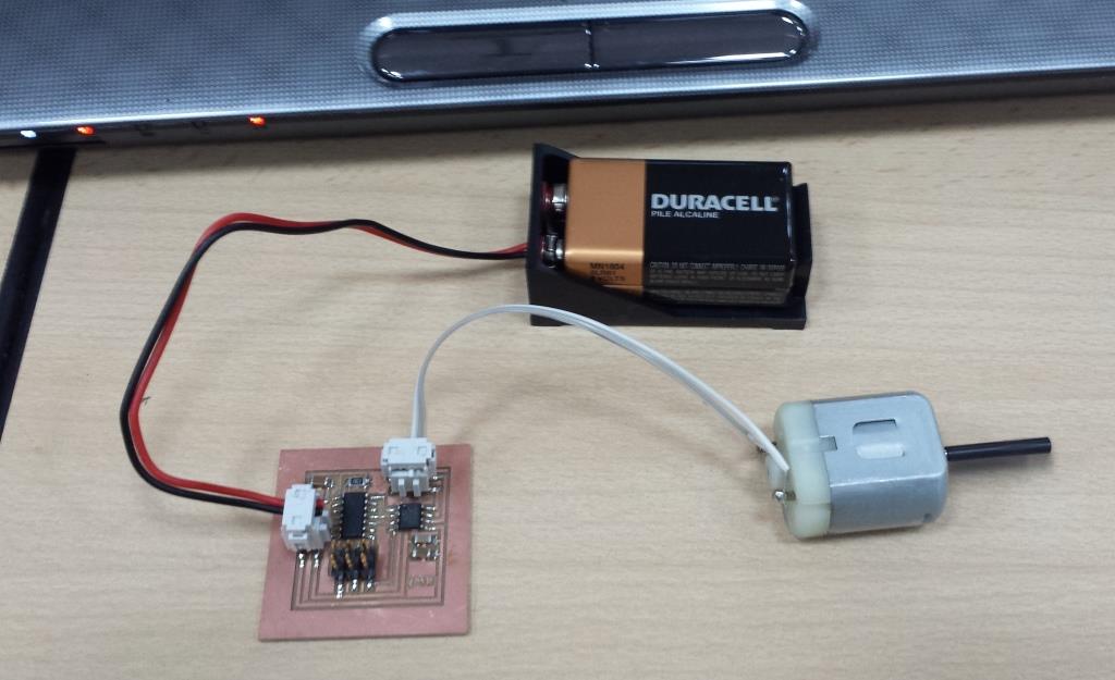 See video of operation (press in picture)  Servomotor. Servo For this has three outputs, two of feeding and of data. Such engines can control your speed and position. In our plate connect a 9V battery, there is also a regulator to supply the system with 5V. The actuators make use of pulse width modulation (PWM) to control the direction or position of the DC motors. Most work in the frequency of fifty Hertz, and the PWM signal has a period of twenty milliseconds. Servo electronics respond within the width of the modulated signal. If the circuits in the actuator receive a signal between 0.5 to 1.4 milliseconds, it is moved clockwise; be 1.6 to 2 milliseconds servomotor moves counterclockwise; 1.5 milliseconds represents a neutral state standards servomotors For configuration connect the ISP programmer to the board and the 9V battery 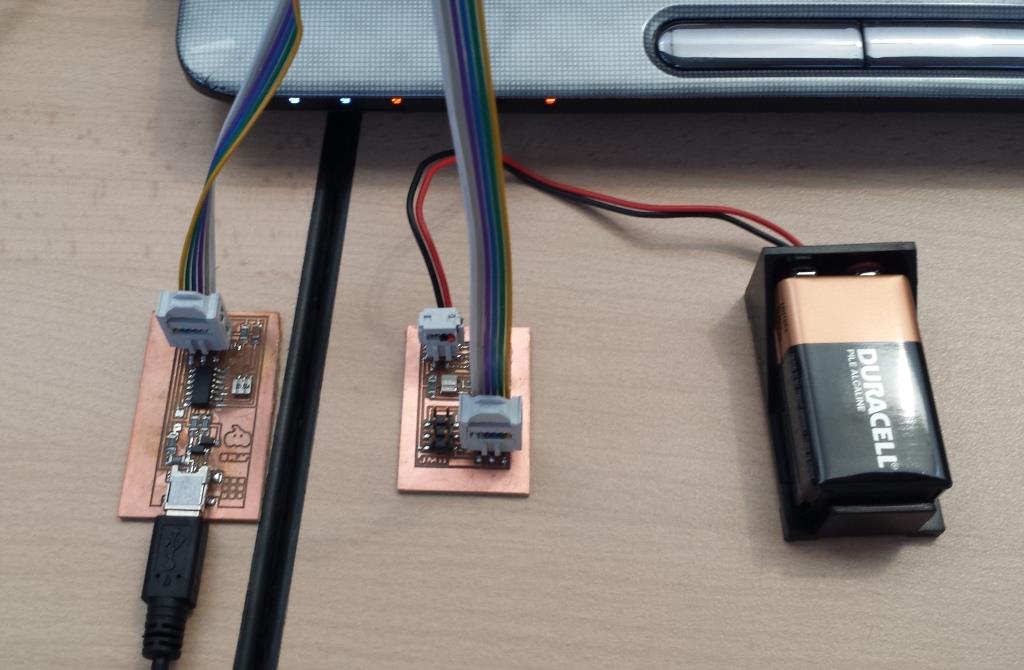 Then unload the C and Makefile (two channel) Motor Academy page files and digitamos Ubuntu terminal (located in the download directory): sudo make -f hello.servo.44.2.make For testing the ISP disconnect and connect the servos, programming makes two servos can work with both S1 and S2. Two-Channels 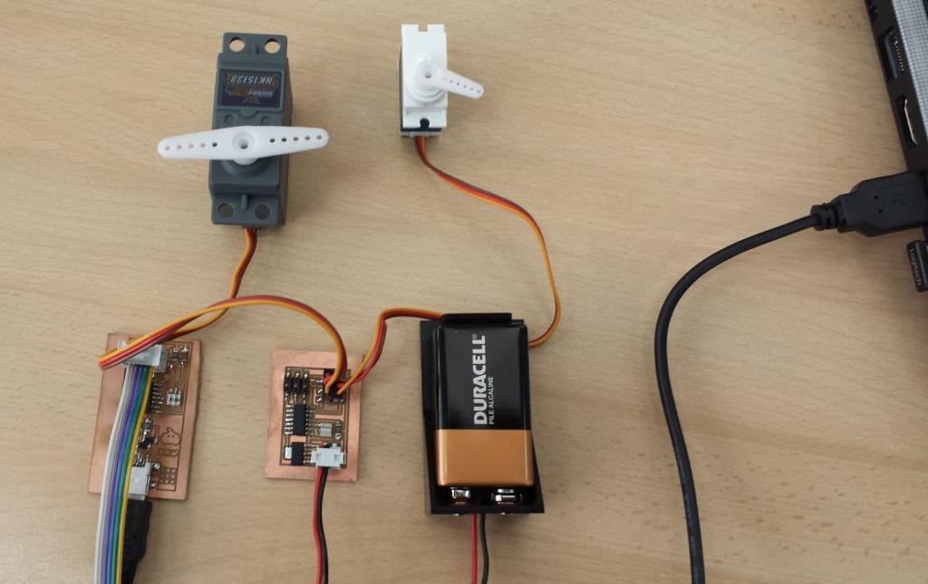 One-Channel 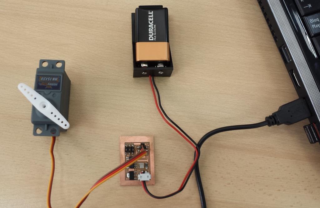 See video of operation (press in picture) 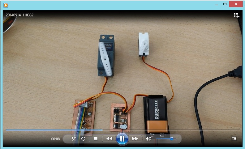 | |