THE FAB ACADEMY 2014
CIRO MEJIA ELIAS

THE FAB ACADEMY 2014
|
|
|
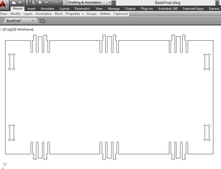
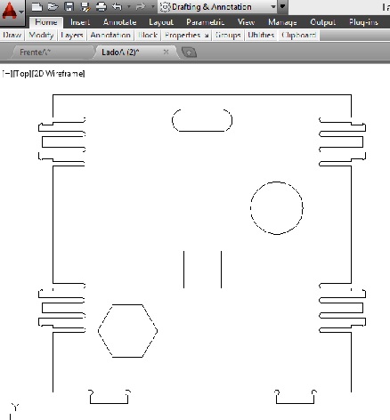
Computer Controlled Machining In this task I made a toys' box, the idea came after seeing my son's toys all around the house. I took the dimensions according to the size of my son, I worked with 15mm MDF and the parts are connected by press-fit. The design was done in Autocad and Inventor Professional and the machining on the ShopBot. The work was divided into two parts: A)Design At this stage the most complicated part was to design the joints between the components, I used press-fit considering the diameter of the cutting bit on the ShopBot (1/4 "). Parts of the Toys Box.
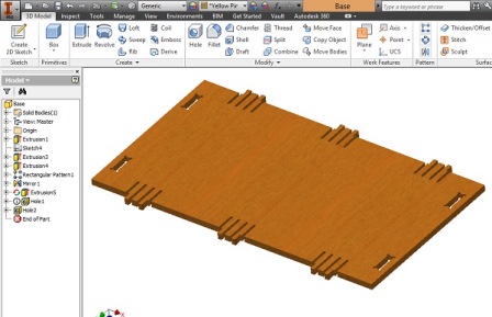
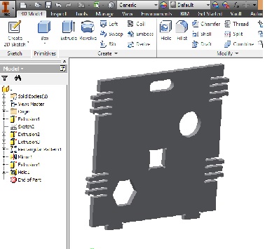
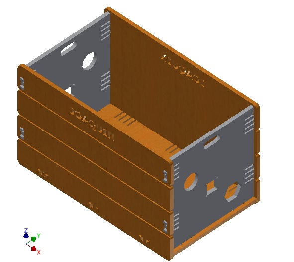 Final design of the toy box
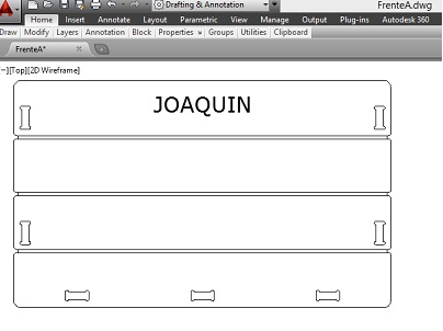
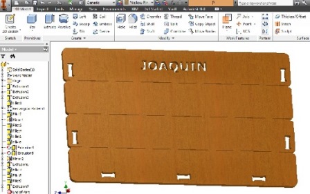
Once the design is completed, I exported it from Inventor to Autocad, to get the DXF file. I had several problems to make this conversion , the software did not show any figure on the Partworks when importing the DXF file , so I had to re do the job in Autocad . I show the tabs and notches created in the components for adjustment below . Note that the depth of the base of the flap should be large enough for the its flexibility. Download CAD Files 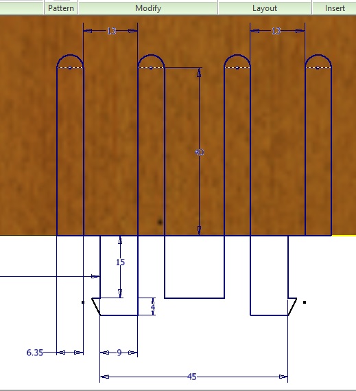 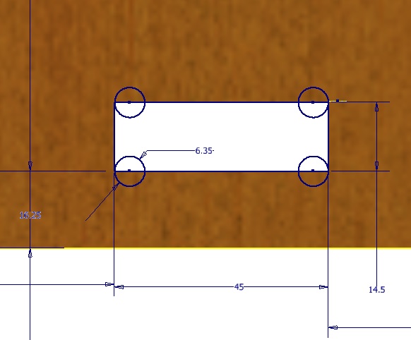 B) Machining the box At this stage the box was machined on the ShopBot considering various aspects . - Material : 15mm MDF - Sheet 122 x 184mm - Work tools: Flat Milling tool 1/4 "diameter. Step 1: Pin a sheet of MDF on the ShopBot table with Spax bolts to prevent movements at work, considering that the table must be clean. 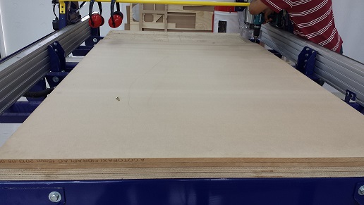 Step 2: Insert the required machining tool in the collet. Step 3: Import the DXF file. Notice that the lines that make the pieces should be joined in Autocad. They can be joined with the " PEDIT " command , you can also join them in the machine software. 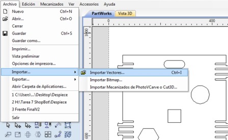 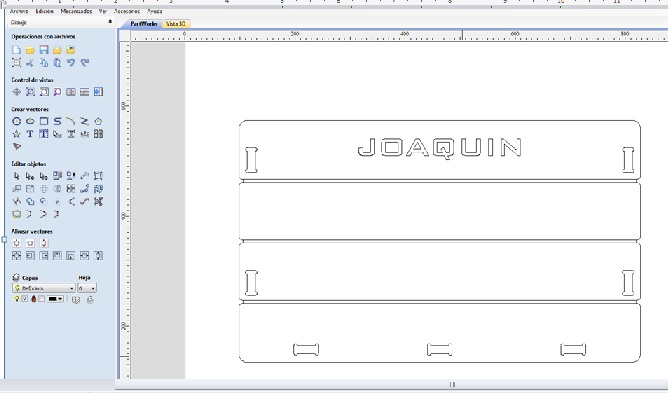 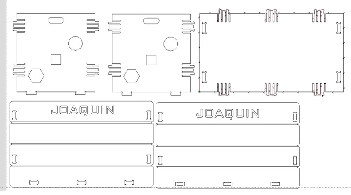 Step 4 : Create the work processes, which in general are three: * Profile: When you want to perform a full cut of the piece, whether internal or external. The parameters to consider are : Depth of cut , tool compensation and number of passes of the tool. * Pocket : When you want to make blind cuts , not interns. The parameters to consider are : Depth of cut and tool. * Drilling : drills . In my work I used the external and internal profile, and pockets also. In the profile I worked with the parameters shown in the graphic: 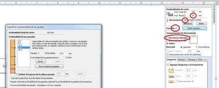 In the pocket I worked with a depth of 4 mm. External and internal profile are shown below. 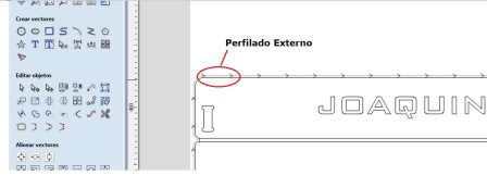 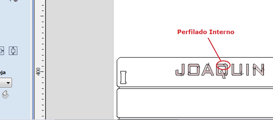 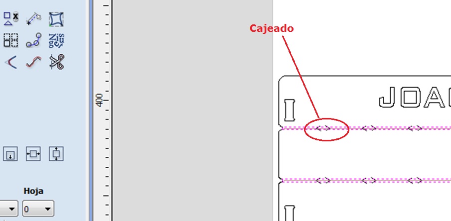 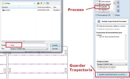 Step 6: Set the ShopBot parameters:
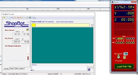 * Position of the tool, axes X and Y * Position of the tool, axis Z, an accessory is used to estimate the height between the bit and the table. 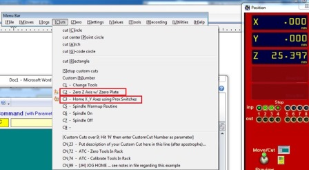 Step 7: Load the file path. 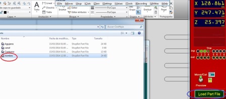 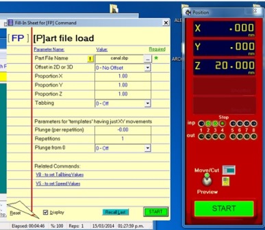 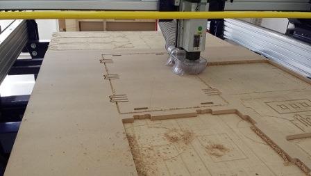 C) Mounting the Box
Assembly was relatively easy, this is due to the measures taken in the design, the tools used were: * Wood rasp * Rubber Hammer * Nose pliers * Sandpaper The steps of the assembly are shown below: 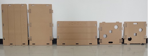 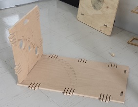 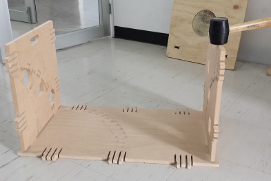 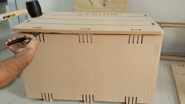 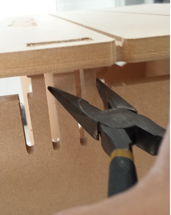 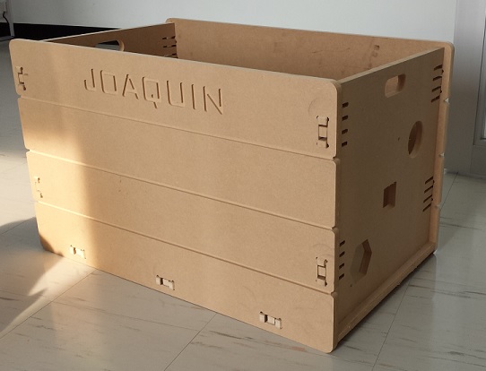 | |||||||||||||