THE FAB ACADEMY 2014
CIRO MEJIA ELIAS

THE FAB ACADEMY 2014
|
|
|
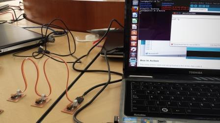
Networking and Communications In this assignment communication between two nodes is done through a wired network, this is an asynchronous serial communication. The steps to follow are: a) Milling plate in MODELA. At this stage in previous assignments as a drill 1/64 and the same parameters in the MODEL milling was used. The plot was obtained from the website of the academy. Bridge: http://academy.cba.mit.edu/classes/networking_communications/bus/hello.bus.45.bridge.traces.png 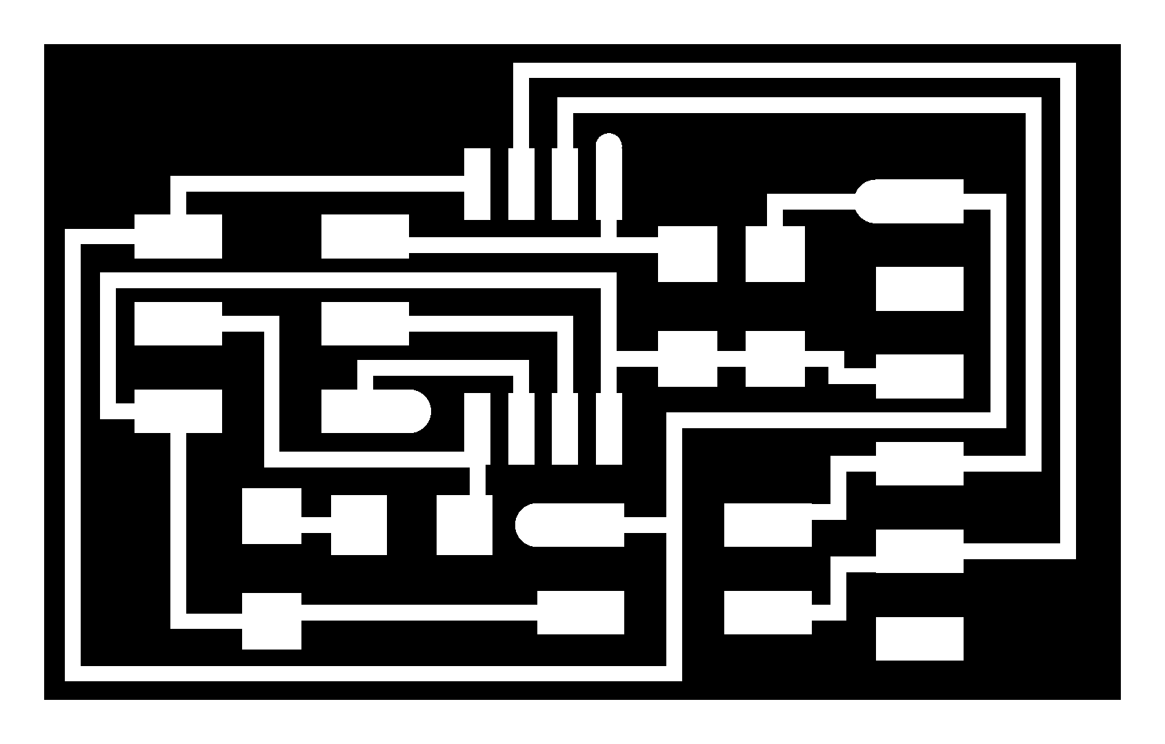 http://academy.cba.mit.edu/classes/networking_communications/bus/hello.bus.45.node.traces.png 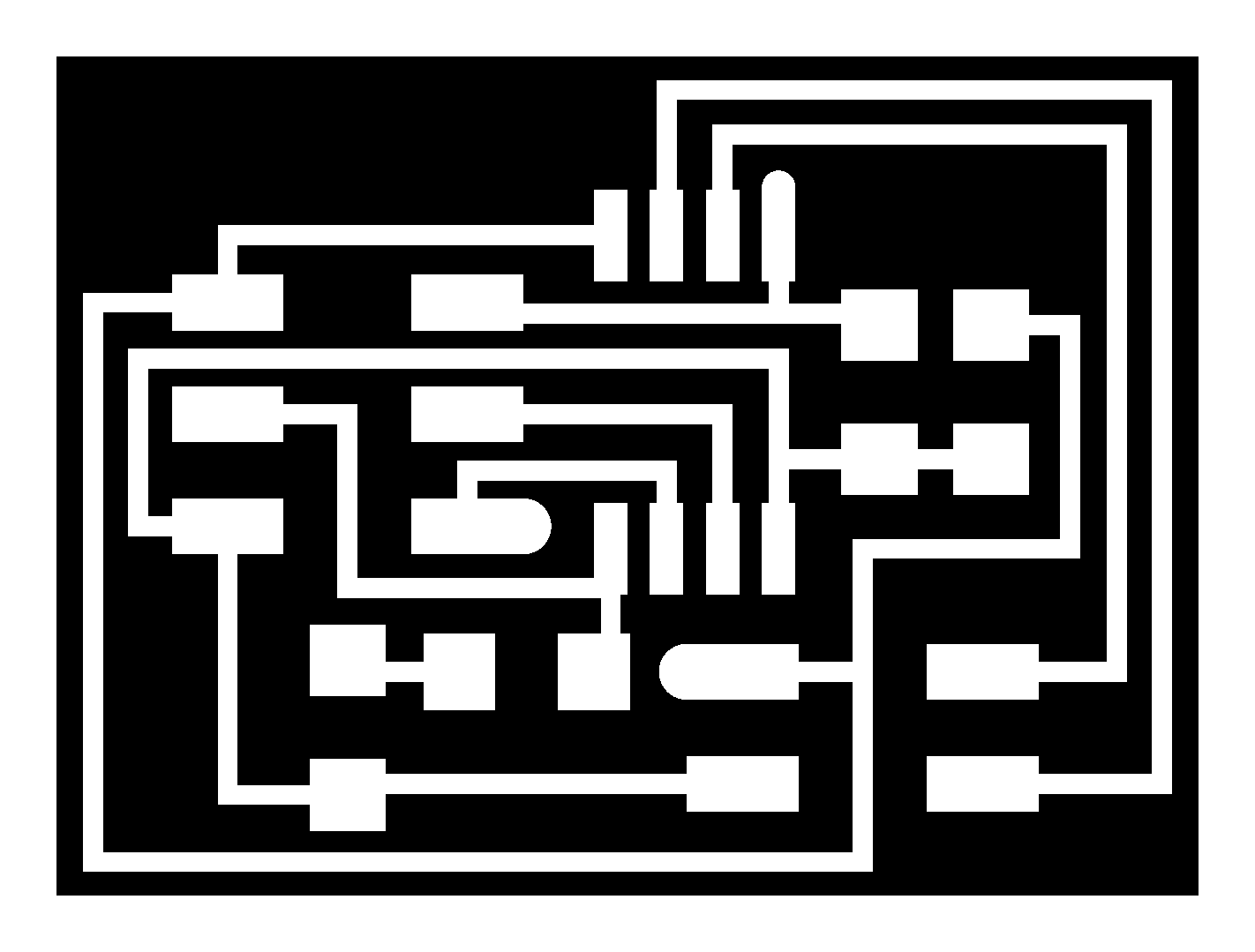 Parameters the MODELA 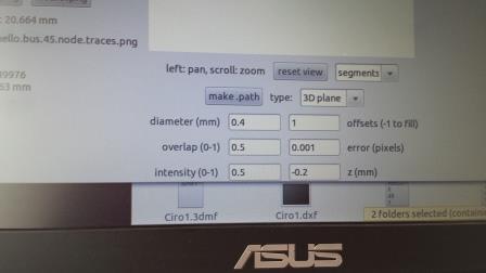 b) Welding the components of the nodes and the bridge board. The components and their arrangement on the board was obtained from the website of the academy. 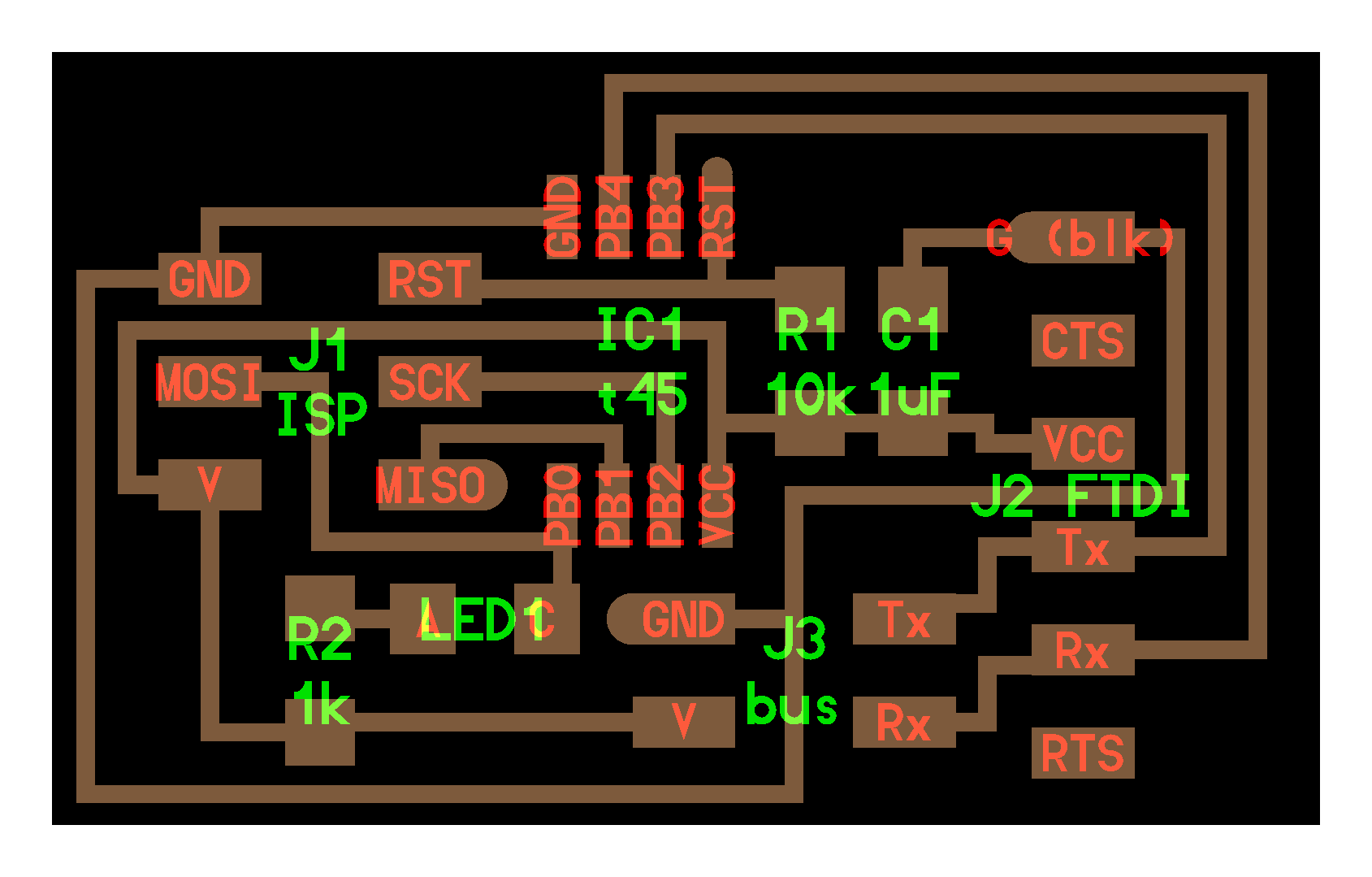 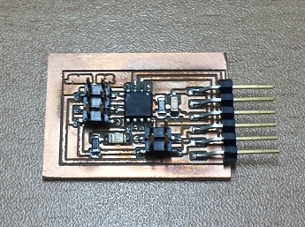 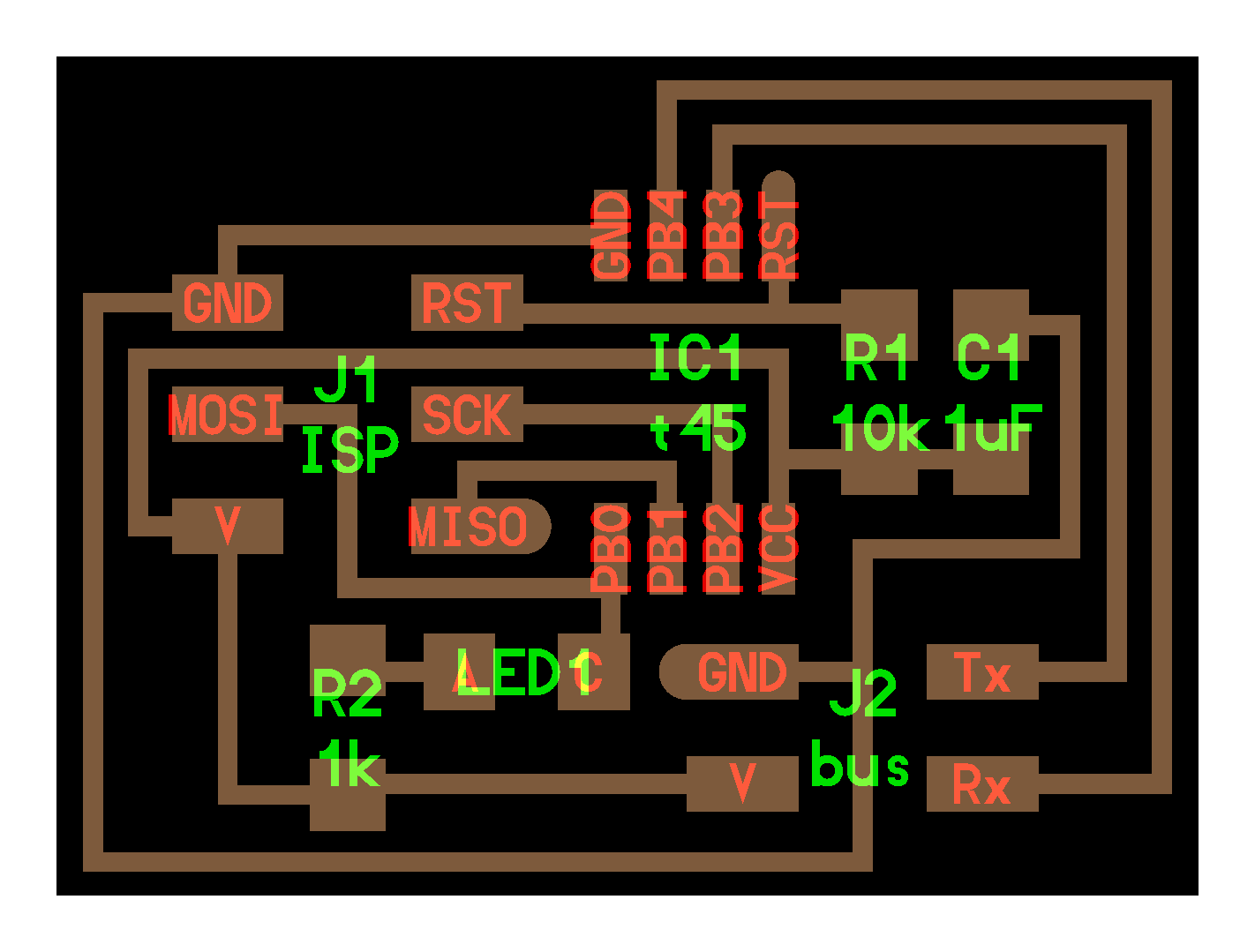 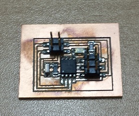 c) Set the nodes and the communication bridge. The configuration for the bridge is: 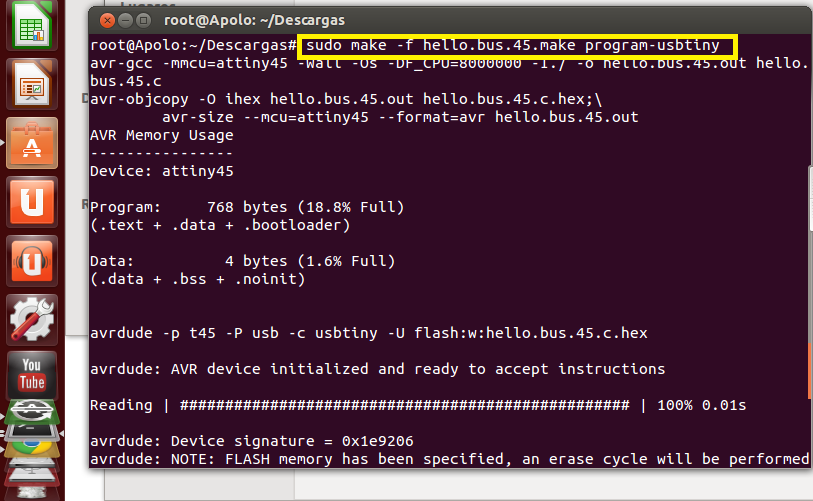 Connect the bridge to your settings
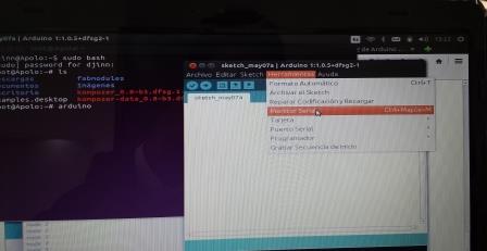
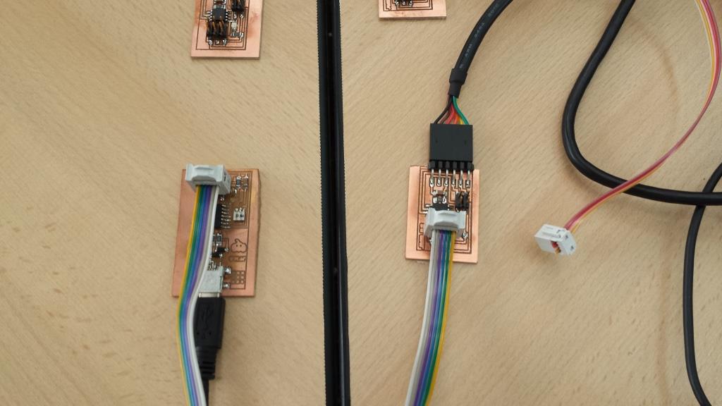 To configure the nodes is necessary to modify the file: hello.bus.45.c, paragraph # define node_id '0 '. For example for the first modification would be like this: # define node_id '1 '. 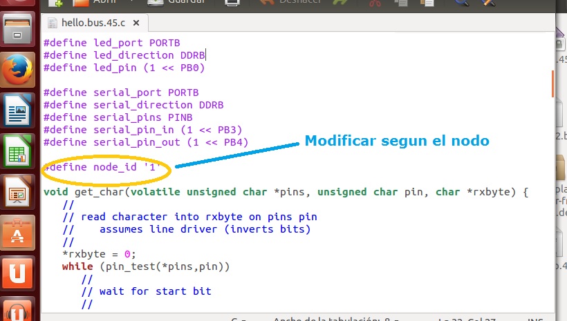 Connect the node to your settings 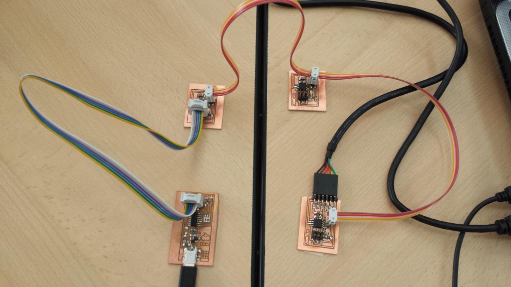 d) Make connections between node and testing - bridge. To verify communication between node and bridge work with the Arduino IDE, with its serial monitor. Getting a correct answer among them.this task we will to some extent by a sensor that we added to an electronic board. Arduino Serial Monitor
  | |