THE FAB ACADEMY 2014
CIRO MEJIA ELIAS

THE FAB ACADEMY 2014
|
|
|
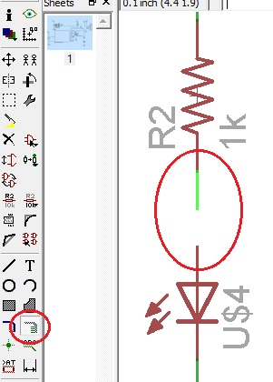
Electronics Design A) Redesign the PCB "echo hello-world" The activity is redesign the "echo hello-world" adding two components: a LED light and one button to create the board. I designed the PCB in the "Freeware" version of the "Eagle" software , this design is divided in two stages: Schematic Stage: The design was easy and friendly, in this stage is only required to add the components of the software library, keeping in mind the names and values of these inputs and outputs. The steps are: - Download the software and install it (http://www.cadsoftusa.com/download-eagle/). - Run and select "Run Freeware". - Create a project, right click, choose the new option and then schematic 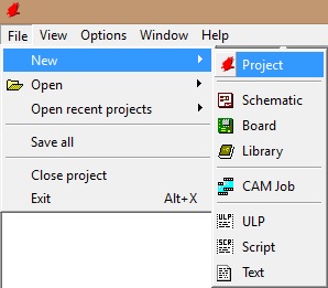 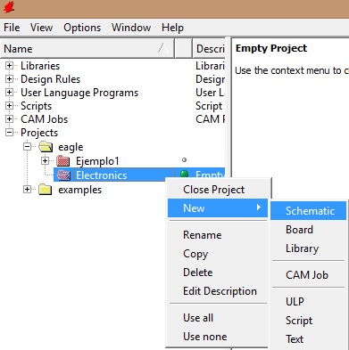 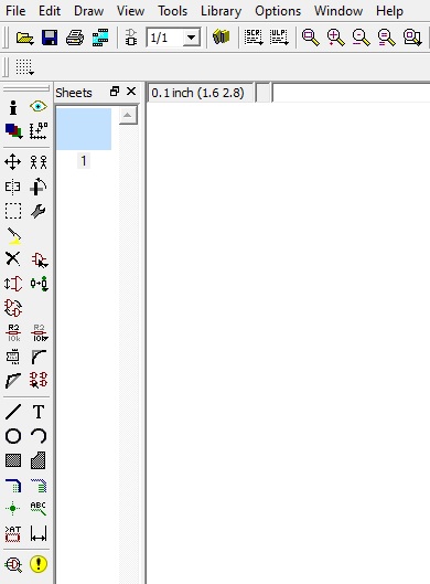 - Add the library components. 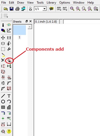 - To search any component, write the name and press enter 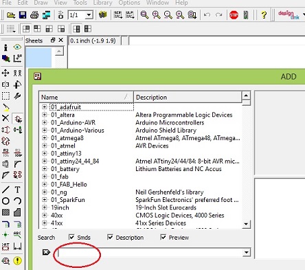 - The selected components were:
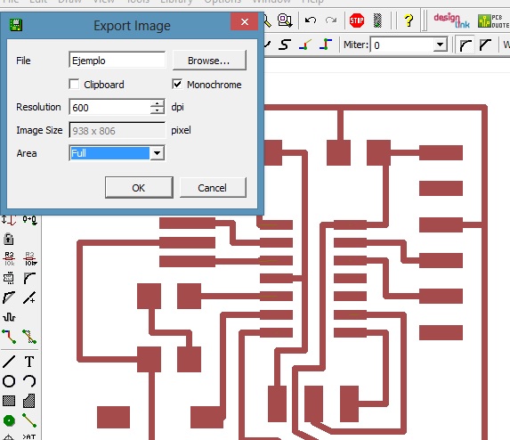
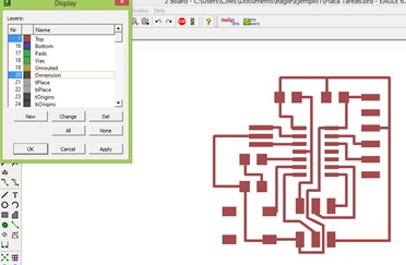
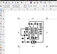
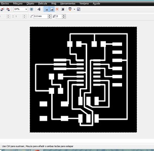
 - To avoid a too complex meshing , links are made by adding names to the input or output of each component : 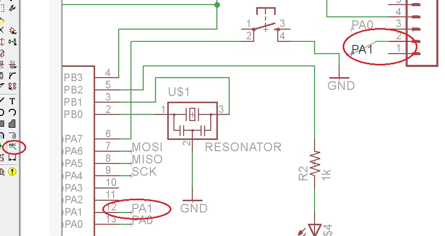 - Check the connections with the command: " ERC " 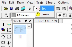 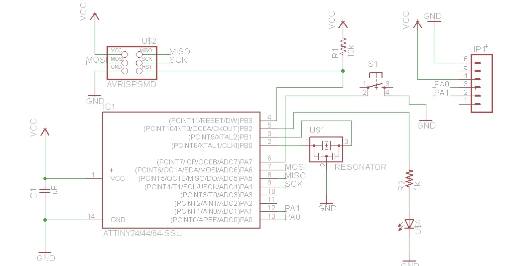 Board Stage: At this stage the tracks of the board are constructed as they will be printed . - Go from schematic to Board  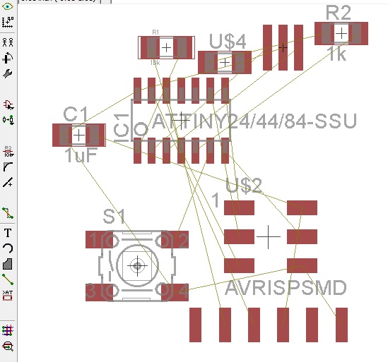 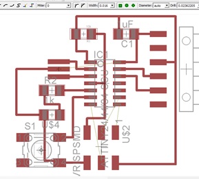 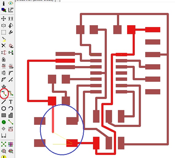 - Check the inputs and outputs of the components with the " Show" command. 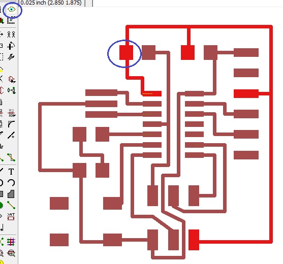 Export to PNG Stage: In this stage the design is exported to PNG format in order to be printed for the "MODELA" machine.
  B) Board Printing We proceded in a similar way that Task 3, with the same configuration parameters. - Load the PNG file and configure the parameters established in the previous task. 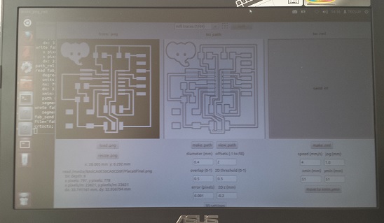 - Print in MODELA 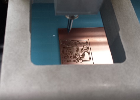 - Board finish. 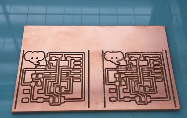 C) Mounting components on the board This time it was much easier , having the experience of task 3 experience. Observe the orientation of the components : Led, Microprocessor and button . - Main Board 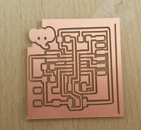 - Components 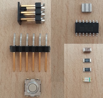 - Final Board 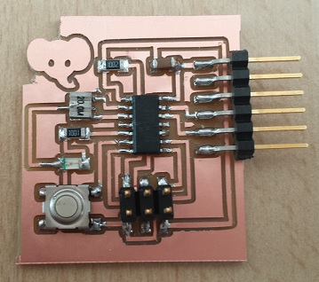 | |