Week 8:
Embedded Programming
Embedded programming ... I don't even know exactly what those two words mean. That scares me 50% and motivates me 50%. It is something that I have always wanted to understand, but that I have always seen too complex to understand. I hope I can understand some elementary basics this week.
The GIF explains my current vision of what it means to code. I hope I can attach another GIF at the end of the week that expresses in a more concrete way what it really is to be a programmer.
The classes that we have had during Wednesday and Thursday morning have maintained the fear / motivation balance that I was telling you about. There have been some concepts that have been interesting to me and that I have understood. While others have totally left me out of the game. I hope that little by little during the week, more and more concepts will enter my head.
The three assignments for this week are:
Group assignment:
• compare the performance and development workflows for other architectures.
Individual assignment:
• Read a microcontroller data sheet.
• Program your board to do something, with as many different programming languages and programming environments as possible.
Group Assignment
For this week's group assignment we had to compare the operation of several microcontrollers and their capabilities. Reviewing the content that I can contribute to the collective knowledge, I think it is better to expose the good work of my colleagues.
They have much more experience than I in these fields and have done a wonderful job of summarizing and understanding how these components work. Below you have the link to their websites where you can find the knowledge that we have shared.
Apart from the tremendous work of summarizing and explaining the comparisons that we have made, which Carla has done, some of my colleagues have used other microcontrollers. You can check on its pages the work done and the comparison with other families of microcontrollers.
In case you don't want to go through allthe information, here is a summary of the work we did:
| Chip | WorkFlow | Framework | Connection | Code | Time to compile & Flash | Sketch memory | Global variable memory | Comment |
|---|---|---|---|---|---|---|---|---|
| ESP32 | ArduinoIDE | Arduino | USB | Arduino | 10s | XXkb | XXkb | |
| ESP32 | ArduinoIDE | ESP library | USB | C | 10s | XXkb | XXkb | |
| ESP32 | ESP-IDF | ESP-IDF | GPIO | C | 10s | XXkb | XXkb | |
| ESP32 | PlatformIO | Arduino | GPIO | Arduino | 10s | XXkb | XXkb | |
| ESP32 | MicroPython | MicroPython | GPIO | Python | 10s | XXkb | XXkb | |
| ESP32 | MicroPython | MicroPython | USB-FTDI | Python | 10s | XXkb | XXkb | |
| ESP32 | MicroPython | MicroPython | WebREPL | Python | slow | XXkb | XXkb |
For each point of the table we can note the following as learning points :
- Workflow: lots of workflows are available for all the board. One should choose the one he feels confortable with because at our programming level there is no much differences. If I had to choose one for ESP-32, ESP-IDF is nice because it fits my chip (ESP32) but Platformio interaction in the terminal is really smooth. So that would be one of those.
- Framework: This is the environment of library you work with. In my case I worked a lot with Arduino and bare C with register interaction. Python was also involved. When working with AVR chip there is sense to use bare C to save on space. But when working with ESP32 it seems that even working only with C there is no much memory to save on because “side libraries” are to be loaded on the chip and the blink code will be a tiny part of it.
- Connection: We saw several ways to connect to our boards ranging from USB-FTDI to Raspberry pi 4 GPIO pins passing by direct wiring connection on flexible board. I enjoyed working with Rpi4 GPIO pins as it avoid using an FTDI board and free a USB port.
- Time to compile and flash: For ESP32 I noted that the flashing time is longer than for other board probably due to the extra features (wifi, bluetooth etc…). Also when working with ESP-IDF, the first build is really slow and I could see a lot of library were loaded.
Individual Assignment
As a starting point for this week I wanted to make a few things clear first. I have practically no knowledge of embedded programming and I want to focus on understanding the basics.
I think it is a super powerful tool, but at the same time very complex and difficult to acquire for a week. I think it is better to focus on understanding the elementary basics and later try to apply those concepts to small practical examples for newbies.
ATtiny1614 Data sheet
Understanding the operation of a microcontroller even superficially is a good starting point for the week. To better understand the information that is exposed in the datasheet, first I will try to do a personal reading. If I see that the content exceeds me I will try to find some type of summary or blog that helps me.
Here is the link to the ATtiny1614 data sheet.
After looking over the datasheet I realize that I am not understanding practically anything of what it says in the document. So I think it is easier to go to theMicrochip website and look for the general data of the microcontroller or somekind of summary.
Summary
Quoting directly from the Microchip website:
The ATtiny1614 is a microcontroller featuring the 8-bit AVR® processor with hardware multiplier, running at up to 20 MHz and with 16 KB Flash, 2 KB SRAM and 128B of EEPROM in a 14-pin package. The series uses the latest Core Independent Peripherals with low-power features, including Event System, intelligent analog and advanced peripherals. The integrated QTouch® peripheral touch controller supports capacitive touch interfaces with proximity sensing and a driven shield.
ATtiny1614 Parameters
| Name | Value |
|---|---|
| Program Memory Type | Flash |
| Program Memory Size (KB) | 16 |
| CPU Speed (MIPS/DMIPS) | 20 |
| SRAM (B) | 2,048 |
| Data EEPROM/HEF (bytes) | 256 |
| Digital Communication Peripherals | 1-UART, 1-SPI, 1-I2C |
| Capture/Compare/PWM Peripherals | 2 Input Capture, 6PWM |
| Timers | 1 x 8-bit, 3 x 16-bit |
| ADC Input | 10 ch, 10-bit |
| Number of Comparators | 3 |
| Temperature Range (°C) | -40 to 125 |
| Operating Voltage Range (V) | 1.8 to 5.5 |
| Pin Count | 14 |
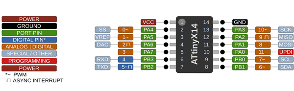
ATtiny1614 Pinout
I consider that one of the most relevant data to use the microcontroller is to know its pinout. The pinout will visually explain to you what each of the device's legs does and the capabilities of each of them. Knowing this information also allows you to design correctly, it offers you the possibility of getting the most out of each of them.
After gathering all this information, I think the best way to continue to understand things is to move on to the practical part. It is possible that during programming I understand some concepts that for now I consider a bit fuzzy.
Program with Arduino IDE
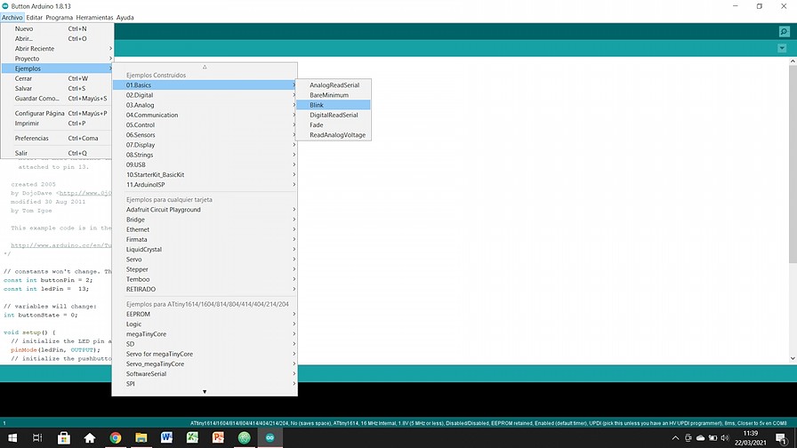
The first system I want to test is the Arduino IDE. This program is called IDE, which stands for "Integrated Development Environment". This IDE will be installed on our PC, it is a very simple environment to use and in it we will write the program that we want the Arduino to execute. Once written, we will load it through USB and the board will begin to work autonomously. (quoting Arduino website words)
Once installed and working, I used the pre-installed Blink program. Arduino IDE has many different codes installed both to test the material (my case) or to write code without having to start from scratch.
But suddenly I started having problems one after the other. Check the next chapter of the web for more information ...
Solve some issues with my boards
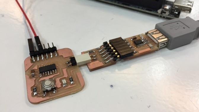
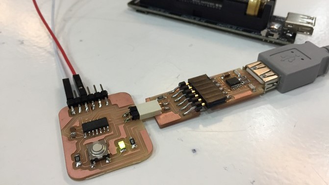
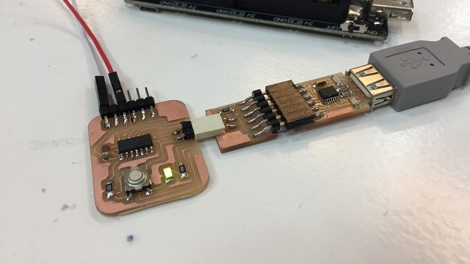
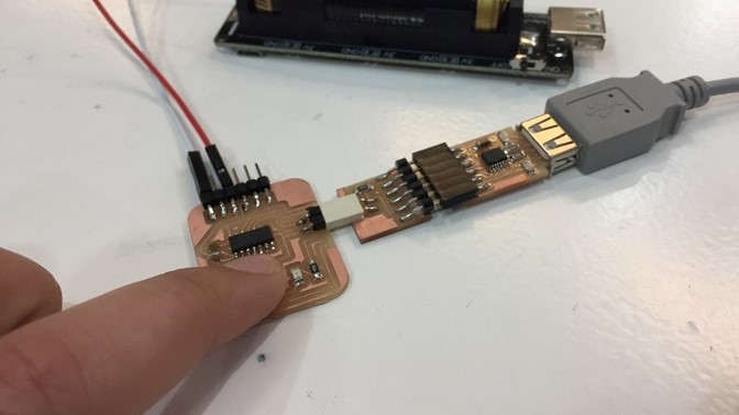
Trying to program some little code with the Arduino IDE, I kept getting an error notifying me that the UTDI was not responding. Trying to find the error with my instructors we discovered where the problem was.
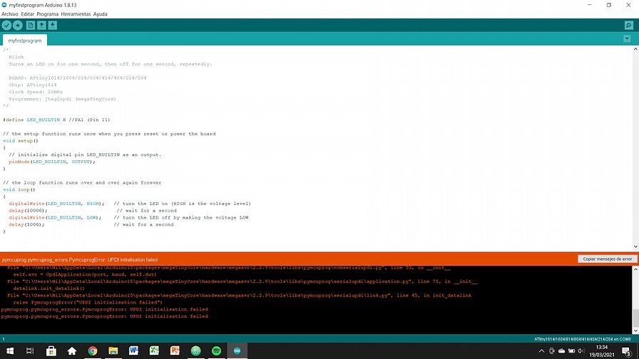
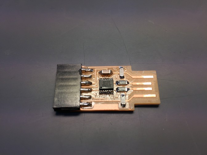
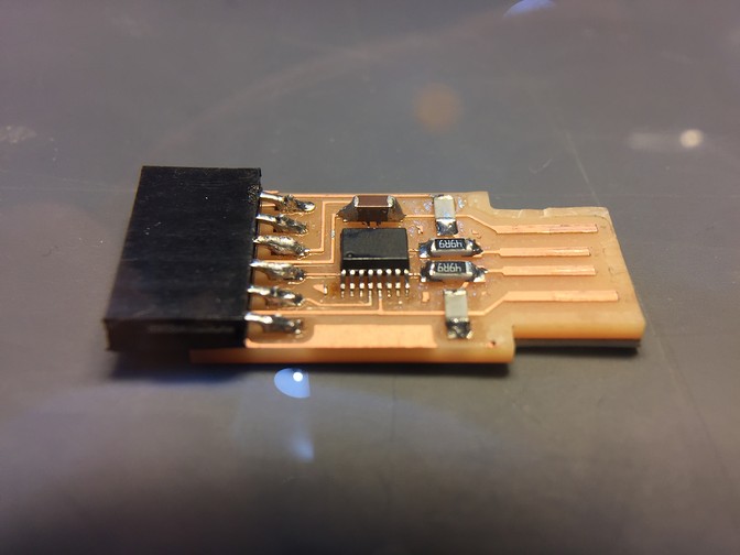
Some of the legs of the FTDI microcontroller were not well soldered or were making poor contact. If you hold the microcontroller with your finger while uploading the program, everything works fine. On the other hand, if you leave the plate loose, you receive the error that the UPDI is not found.
Logically I had to solve the problem by correctly soldering the FTDI microcontroller. In the following images you can see in summary the process of solving the problem.
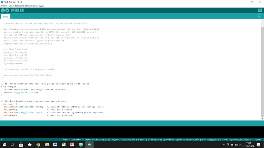
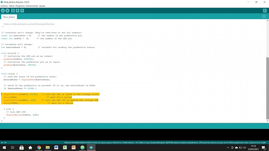
Blink
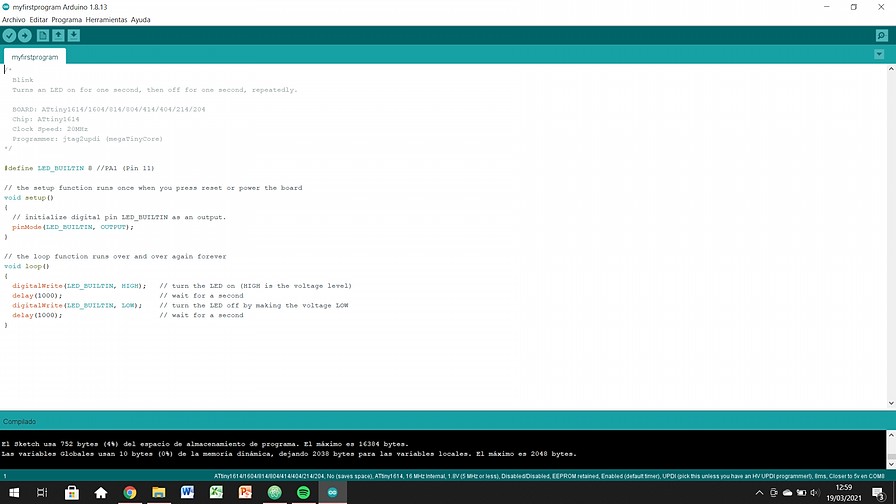
Once the connection and welding problems were solved, I finally managed to program it correctly with Blink mode. First try btw!
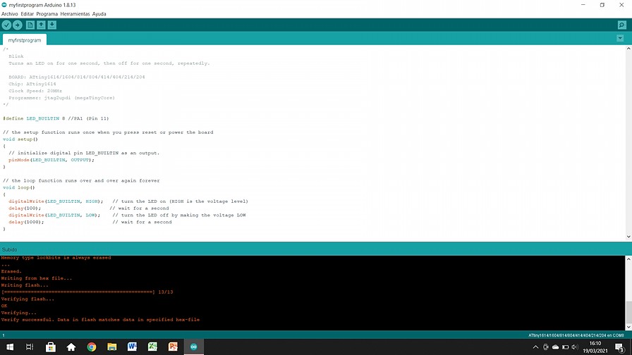
Here is the code I used:
/*
Blink
Turns an LED on for one second, then off for one second, repeatedly.

BOARD: ATtiny1614/1604/814/804/414/404/214/204
Chip: ATtiny1614
Clock Speed: 20MHz
Programmer: jtag2updi (megaTinyCore)
*/

#define LED_BUILTIN 2 //PA1 (Pin 11)

// the setup function runs once when you press reset or power the board
void setup()
{
// initialize digital pin LED_BUILTIN as an output.
pinMode(LED_BUILTIN, OUTPUT);
}

// the loop function runs over and over again forever
void loop()
{
  digitalWrite(LED_BUILTIN, HIGH);   // turn the LED on (HIGH is the voltage level)
  delay(100);                       // wait for a second
  digitalWrite(LED_BUILTIN, LOW);    // turn the LED off by making the voltage LOW
  delay(100);                       // wait for a second
}
Button
So far I was only using the Output of my ATtiny1614 so I thought I'd find some pre-installed program that could mix the button action as Input and the LED as Output. The perfect program was "Digital> Button". Having the FTDI issues resolved, it also compiled the first time.
In this case, I define the button as input, which should turn off the LED while the button is pressed. On the other hand, the LED is on permanently as Ouput, until the button is pressed. I think it is the first time that I am seeing clearly what microcontrollers are for.
Here is the code I used:
										/*
Button

Turns on and off a light emitting diode(LED) connected to digital pin 13,
when pressing a pushbutton attached to pin 2.

The circuit:
- LED attached from pin 13 to ground
- pushbutton attached to pin 2 from +5V
- 10K resistor attached to pin 2 from ground
- Note: on most Arduinos there is already an LED on the board
		    attached to pin 13.

created 2005
by DojoDave
modified 30 Aug 2011
by Tom Igoe

This example code is in the public domain.

http://www.arduino.cc/en/Tutorial/Button
*/

// constants won't change. They're used here to set pin numbers:
const int buttonPin = 9;     // the number of the pushbutton pin
const int ledPin =  8;      // the number of the LED pin

// variables will change:
int buttonState = 0;         // variable for reading the pushbutton status

void setup() {
  // initialize the LED pin as an output:
  pinMode(ledPin, OUTPUT);
  // initialize the pushbutton pin as an input:
  pinMode(buttonPin, INPUT);
}

void loop() {
	// read the state of the pushbutton value:
	buttonState = digitalRead(buttonPin);

	// check if the pushbutton is pressed. If it is, the buttonState is HIGH:
	if (buttonState == HIGH) {

		 digitalWrite(ledPin, HIGH);

}
else {
	// turn LED off:
		 digitalWrite(ledPin, LOW);
	}
}
Button + Blink
Once I got to the point that input and output were working together, I don't know what else to do to continue testing embedded programming. But it occurs to me to merge the two programs to start learning how the code itself works.
Here is the code I used:
										/*
	  Blink + Button

	  Turns on and off a light emitting diode(LED) connected to digital pin 13,
	  when pressing a pushbutton attached to pin 2.

	  The circuit:
	  - LED attached from pin 13 to ground
	  - pushbutton attached to pin 2 from +5V
	  - 10K resistor attached to pin 2 from ground

	  - Note: on most Arduinos there is already an LED on the board
	    attached to pin 13.

	  created 2005
	  by DojoDave
	  modified 30 Aug 2011
	  by Tom Igoe

	  This example code is in the public domain.

	  http://www.arduino.cc/en/Tutorial/Button
	*/

	// constants won't change. They're used here to set pin numbers:
	const int buttonPin = 9;     // the number of the pushbutton pin
	const int ledPin =  8;      // the number of the LED pin

	// variables will change:
	int buttonState = 0;         // variable for reading the pushbutton status

	void setup() {
	  // initialize the LED pin as an output:
	  pinMode(ledPin, OUTPUT);
	  // initialize the pushbutton pin as an input:
	  pinMode(buttonPin, INPUT);
	}

	void loop() {
	  // read the state of the pushbutton value:
	  buttonState = digitalRead(buttonPin);

	  // check if the pushbutton is pressed. If it is, the buttonState is HIGH:
	  if (buttonState == HIGH) {

			// turn LED off:
			digitalWrite(ledPin, LOW);
		}

	  }
		else {

			digitalWrite(ledPin, HIGH);   // turn the LED on (HIGH is the voltage level)
		  delay(100);                       // wait for a second
		  digitalWrite(ledPin, LOW);    // turn the LED off by making the voltage LOW
		  delay(1000);                       // wait for a second
	}
Here you will find all the original files for this week's assignment.
Adressing Registers
After taking the first steps with the Arduino IDE, which from what I have been told, is the easiest to learn, I also want to learn a little about adressing registers. I think it is a good way to make a comparison between methods of making code.
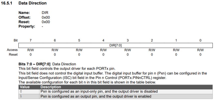
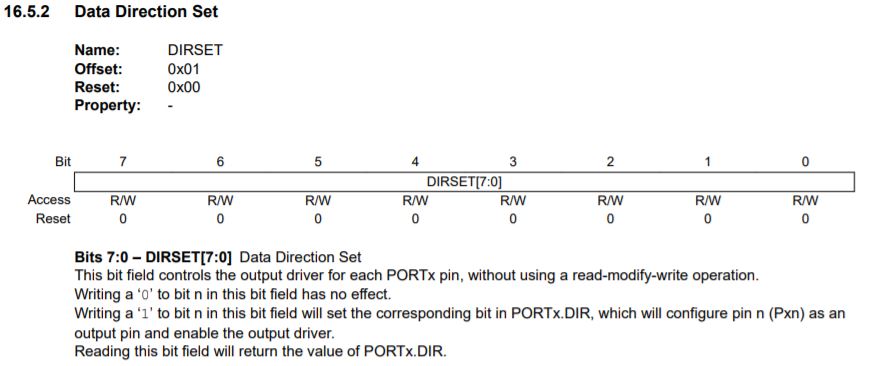
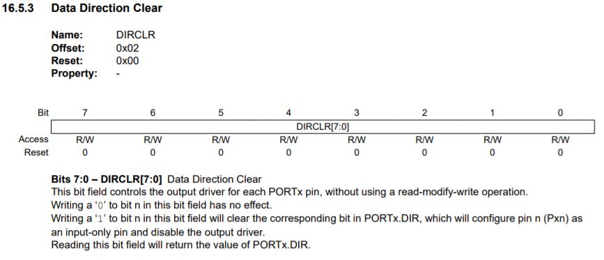
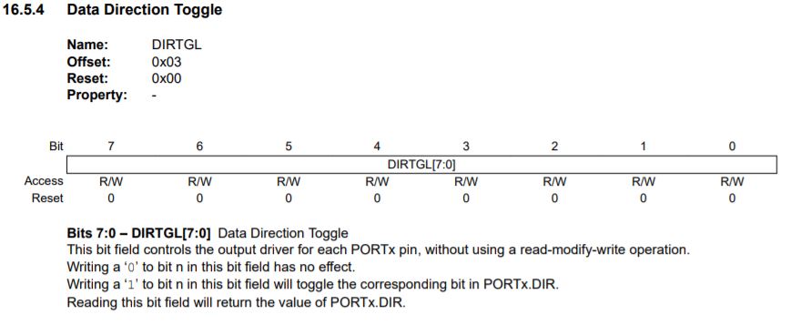
The first thing I have to understand is what instructions I can use, what they are for and how they are categorized. For that I use the ATTiny1614 datasheet to see what options I have. After reading it, I come to the conclusion that there are 3 great instructions:
- PORTx.DIR:Allows you to configure whether the pins will be output or input. (1_OUTPUT; 0_INPUT)
- PORTX.OUT:Writes the output signal to the output that has been configured. (1_HIGH; 0_LOW, on INPUT pins 1_PULLUP)
- PORTx.IN:It allows obtaining the reading of pins configured as IN. (1_HIGH; 0_LOW)
Once the general modes have been established, each of these functions in turn presents some language shortcuts:
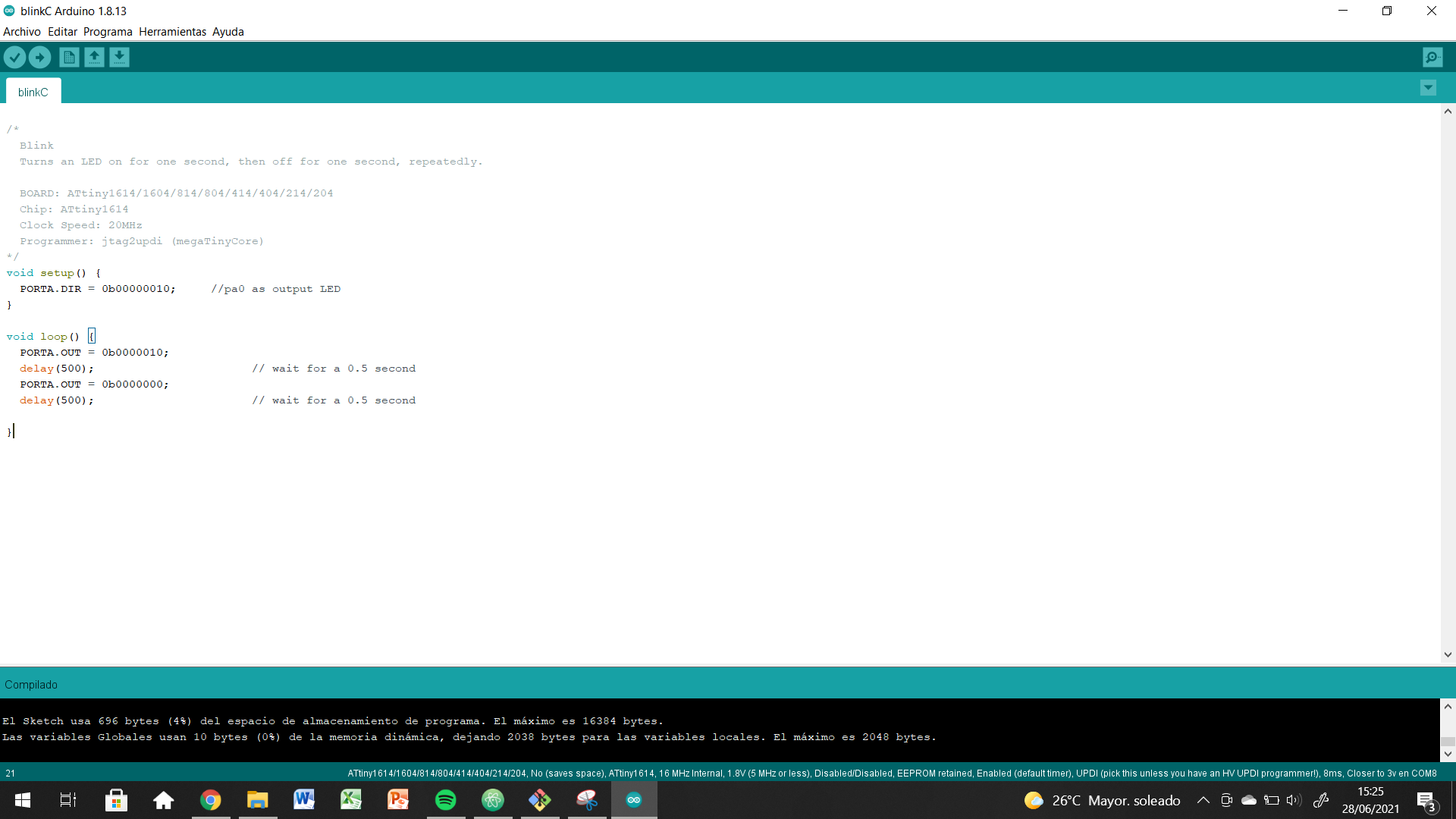
Blink C
To test it for myself I have decided to do the blink that I did with Arduino but this time using this other programming technique.
/*
  BlinkC
  Turns an LED on for one second, then off for one second, repeatedly.

  BOARD: ATtiny1614/1604/814/804/414/404/214/204
  Chip: ATtiny1614
  Clock Speed: 20MHz
  Programmer: jtag2updi (megaTinyCore)
*/
void setup() {
  PORTA.DIR = 0b00000010;     //pa0 as output LED
}

void loop() {
  PORTA.OUT = 0b0000010;
  delay(500);                       // wait for a 0.5 second
  PORTA.OUT = 0b0000000;
  delay(500);                       // wait for a 0.5 second

}
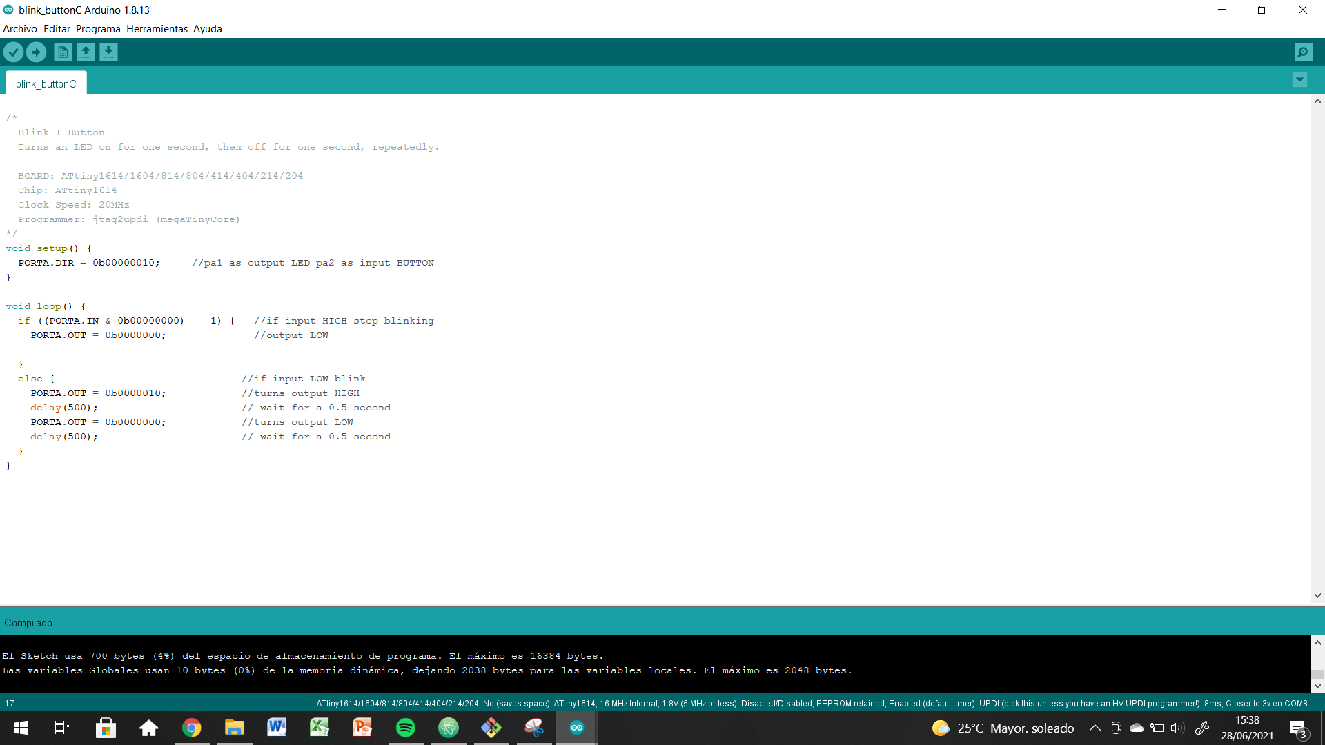
Blink + Button C
In this other code, in addition to working with the output, I add the input that will be the button. The idea of the code is that the LED blinks while the button is not pressed. When pressed, it should stop and remain off.
/*
  Blink + Button
  Turns an LED on for one second, then off for one second, repeatedly.

  BOARD: ATtiny1614/1604/814/804/414/404/214/204
  Chip: ATtiny1614
  Clock Speed: 20MHz
  Programmer: jtag2updi (megaTinyCore)
*/
void setup() {
  PORTA.DIR = 0b00000010;     //pa1 as output LED pa2 as input BUTTON
}

void loop() {
  if ((PORTA.IN & 0b00000000) == 1) {   //if input HIGH....
    PORTA.OUT = 0b0000000;              //stop blinking

  }
  else {                              //if input LOW blink
    PORTA.OUT = 0b0000010;            //turns output HIGH
    delay(500);                       // wait for a 0.5 second
    PORTA.OUT = 0b0000000;            //turns output LOW
    delay(500);                       // wait for a 0.5 second
  }
}
Week Conclusions
I started this week quite scared with the subject we were dealing with but little by little I have lost my fear. I find electronic programming and control to be great tools for design. They open up a world of possibilities.
I find it especially useful for me for the part of being able to go further in product development. Until now I just bought components that met my needs and disregarded everything else. Now I believe that with patience and learning as much as possible from this world, I could get to the point of doing all my electronic from A to Z.
Although I do not believe too much what I am going to say: I AM LOOKING FORWARD TO SEE INPUT AND OUTPUT.
I think it will really be during that week that I will be able to see the possibilities that programming offers me.
Original Files
Link to Original files from this week.
What to improve for next assignments?
These last few weeks I have been juggling graduate school, work, and personal issues. Finally, it seems that things are beginning to calm down and although hard days await me, when they pass I will be much calmer.
What to keep an eye on during week 9?
· Finish my personal business to buy time for the Fab Academy.
· Maintaining a positive attitude and having a good time.
· Start developing my final project officially. We are in the midst of graduate school and it is becoming important that all progress is made