Week 13:
Output Devices
This week focuses on understanding how to use outputs. This is more complex than it might seem at first, because each output is a completely different world. Although there are some points in common such as the software (which although different is nothing more than configuring the pins of the microcontroller), the connections or the fact of launching data to an external element; the operation and purpose of each one is totally different.
In my case, I would like to link this week with the input week we did a couple of weeks ago. The idea is to do a first iteration of the electronics of my final project. The idea is to read color in order to translate it into LEDs that copy that color. I will start the week focusing on designing a PCB that allows me to receive data from a color sensor and be able to emit it to different types of LEDs. If I had time it would be interesting to try other outputs but for now I prefer to stay focused on the final project.
Hopefully this week you learn as much as in Input and that the results are satisfactory. For now I see that the new digital sensor I have is complex and although it is not part of this week's assignment, I think it will be useful to understand it.
The assignments for this week are:
Group assignment:
• Measure the power consumption of an output device
Individual assignment:
• Add an output device to a microcontroller board you've designed.
• Program it to do something.
Group Assignment
In the same way as last week, Adrien has taken command of the Group Assignment and has laid out the result on his we. Below you have a small window in which to see the material that we have tested.
My contribution to the group work has been the reading of the consumption of the Adafruit Neopixel LEDs. It is surprising how these LEDs so "simple" at first glance, can have such high consumptions when they accumulate inside an LED strip. Check the weekly group assignment in Adrien's Website!
I think my colleagues will expand the information as they finish their own projects. The end result is sure to be great.
Individual Assignment
The idea of this week as I was telling you is to familiarize myself with the possible outputs of my final project. For now, I only consider lighting as output, although this may change later. For now I think it is a good idea to understand how they work, that inside a lamp it is a key element.
Input assignment: Output RGB LEDs
Before entering the week that begins, I want to show you the Outpput work that I did during Input week, to get to control the lights that illuminate the objects read by my sensor.
RGB Blink
The first step was to turn on the lights and understand how the three color channels within each can be controlled. For this and with the help of Josep (instructor) I understood and developed my first code made entirely by me. It is a simple blink system that alternates between the 3 RGB color channels in small intervals. I think it is a good way to check that everything works correctly. AND IT IS GREAT !!!
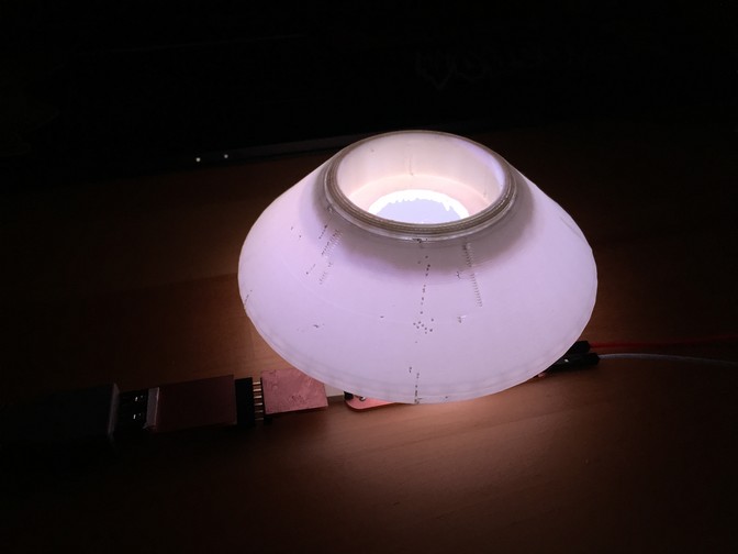
The LEDs are very powerful and the phone has trouble focusing in the sudden change of light. Here is another video in which they are covered with a PLA screen.
int BL = 2;
int RL = 0;
int GL = 1;
int BR = 10;
int RR = 6;
int GR = 7;
int lectura;
void setup() {
// initialize digital pin LED_BUILTIN as an output.
Serial.begin(9600);
pinMode(BL, OUTPUT); //
pinMode(GL, OUTPUT);
pinMode(RL, OUTPUT);
pinMode(BR, OUTPUT);
pinMode(RR, OUTPUT);
pinMode(GR, OUTPUT);
digitalWrite(BL, HIGH);
digitalWrite(GL, HIGH);
digitalWrite(RL, HIGH);
digitalWrite(BR, HIGH);
digitalWrite(RR, HIGH);
digitalWrite(GR, HIGH);
pinMode(3, INPUT);
}
void loop() {
lectura = analogRead(3);
Serial.println(analogRead(3));
delay(1000);
blinkRed();
blinkGreen();
blinkBlue();
//whiteLight();
}
void blinkRed() {
digitalWrite(RL, HIGH);
digitalWrite(RR, HIGH);
delay(100);                       // wait for a second
digitalWrite(RL, LOW);
digitalWrite(RR, LOW);
delay(100);                       // wait for a second
digitalWrite(RL, HIGH);
digitalWrite(RR, HIGH);
delay(100);                       // wait for a second
}
void blinkGreen() {
digitalWrite(GL, HIGH);
digitalWrite(GR, HIGH);
delay(100);                       // wait for a second
digitalWrite(GL, LOW);
digitalWrite(GR, LOW);
delay(100);                       // wait for a second
digitalWrite(GL, HIGH);
digitalWrite(GR, HIGH);
delay(100);                       // wait for a second
}
void blinkBlue() {
digitalWrite(BL, HIGH);
digitalWrite(BR, HIGH);
delay(100);                       // wait for a second
digitalWrite(BL, LOW);
digitalWrite(BR, LOW);
delay(100);                       // wait for a second
digitalWrite(BL, HIGH);
digitalWrite(BR, HIGH);
delay(100);                       // wait for a second
}
White Light
The next step to get on with the color reading was to generate white light to be able to bounce off the colored surfaces and have the sensor read the wavelength it receives back. For this reason, in this second program, I activate the three color phases at maximum intensity. The color does not turn out to be pure white, but I think that when we get to future weeks of programming, I will be able to modulate the channels and get closer to the purest white possible.
int BL = 2;
int RL = 0;
int GL = 1;
int BR = 10;
int RR = 6;
int GR = 7;
int lectura;
void setup() {
// initialize digital pin LED_BUILTIN as an output.
Serial.begin(9600);
pinMode(BL, OUTPUT); //
pinMode(GL, OUTPUT);
pinMode(RL, OUTPUT);
pinMode(BR, OUTPUT);
pinMode(RR, OUTPUT);
pinMode(GR, OUTPUT);
digitalWrite(BL, HIGH);
digitalWrite(GL, HIGH);
digitalWrite(RL, HIGH);
digitalWrite(BR, HIGH);
digitalWrite(RR, HIGH);
digitalWrite(GR, HIGH);
pinMode(3, INPUT);
}
void loop() {
lectura = analogRead(3);
Serial.println(analogRead(3));
delay(1000);
//blinkRed();
//blinkGreen();
//blinkBlue();
whiteLight();
}
void whiteLight() {
digitalWrite(BL, LOW);
digitalWrite(GL, LOW);
digitalWrite(RL, LOW);
digitalWrite(BR, LOW);
digitalWrite(RR, LOW);
digitalWrite(GR, LOW);
}
Plans for the week
In order to be able to fulfill the assignment and with the needs that I had for the final project, I have decided this week to make my own arduino or PCB with open pins to be able to manage several inputs and outputs simultaneously.
Although I will be able to realize the full potential later when the project has more development, I think it is a good idea for three reasons:
- I think that having my own "motherboard" can be interesting to learn about the operation of these and how to work around microcontrollers but without closing doors.
- For the final project, and specifically the first iteration, it is practically all I need.
- Continuing to learn about electronics and in this case about open pinout PCB design, is still one of the things that I value the most about FabAcademy.
Get to know the Output
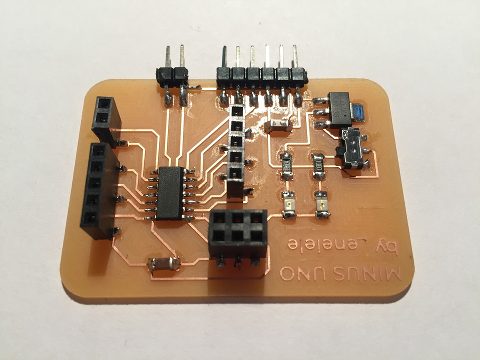
I started the week working with an Arduino UNO, to avoid debugging as much as possible while learning about my output. That's where the idea came from to make my own open PCB. Since I don't know much about electronics yet, I found the name MINUSUNO funny.
MINUSUNO 0.0
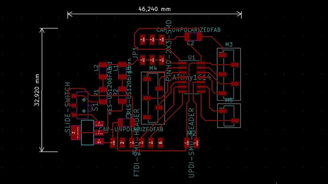
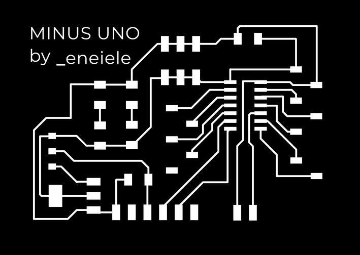
The week's workflow is no different from previous weeks, designing the PCB according to the characteristics I need from the microcontroller, reading datasheets, making decisions, designing with Kicad, retouching with Illustrator, milling and soldering.
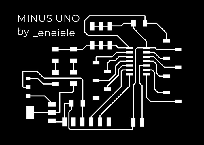
Kicad Schematics and PCB
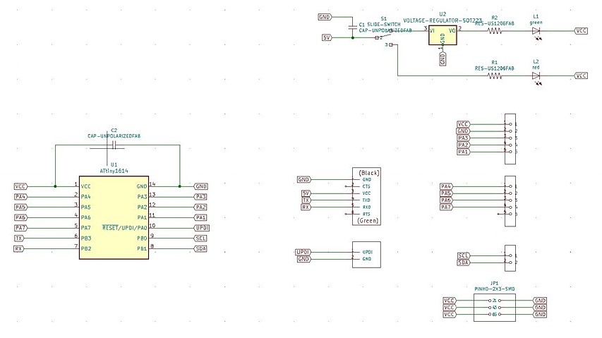
The functions I want to surround the ATtiny1614 with are:
- Leave all programmable pins open with female sockets
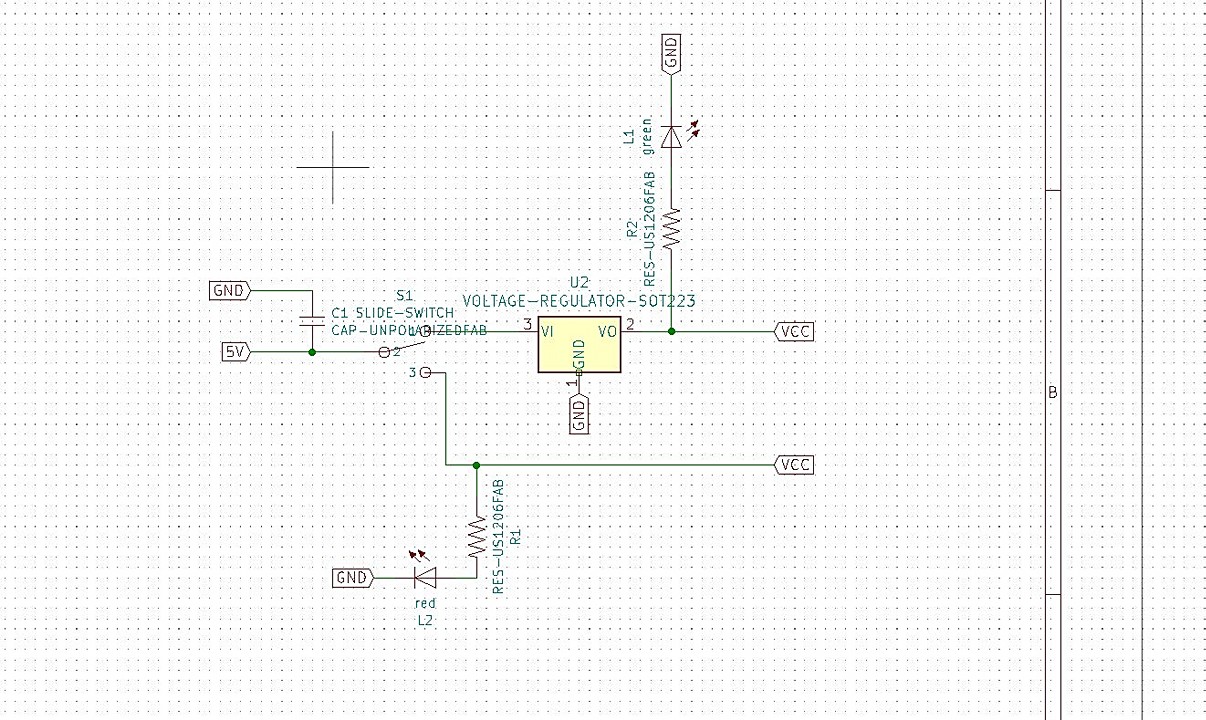
- and 3.3V through a voltage regulator and a switch
- A small system of LEDs to be able to receive feedback on what voltage you are working at
- Open the I2C pins to prepare in advance for networking week
- Cross RX and TX to be able to read data through the serial monitor
- Multiply and open the GND and VCC pins to be able to give voltage to inputs and outputs from the same device
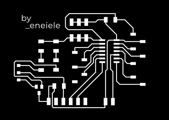
After designing the system in the Kicad schematis, here is the final result. They are not complex but the datasheets research work was not easy, nor short hahaha.
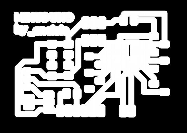
Improving my milling game
I fully appreciated this point to my colleague Diego, who explained to me how to carry out the following process. Check the process on their website if your explanation seems simpler to you.
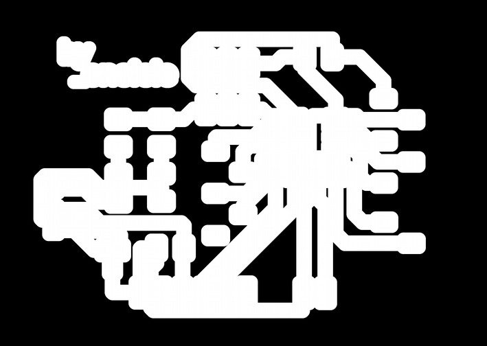
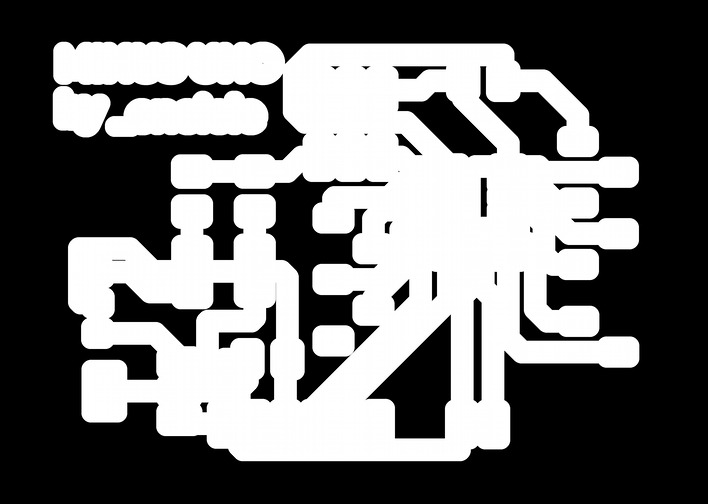
Basically Diego's system consists of milling in three stages:
- Mill the PCB traces, as always
- Use the offset image of the Mods so that through some settings changes, you can clean all the excess copper with the 1/32 "endmill.
- Cut the PCB using the 1/32 "endmill, also as usual

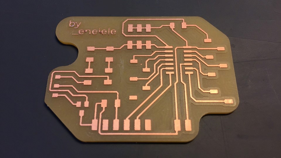
Results and Soldering
The results, although not perfect, I think they improve a lot from those of previous weeks.
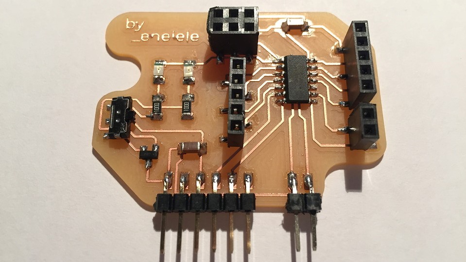
While I was soldering I realized that I had made a mistake: I had confused the 3.3V voltage regulator. In the Lab we have 100mA max and 1A max, as I did not know those components too much, I was wrong with the footprint and it was not to connect the Neopixels since they consume around 170mA per LED strip. The only possible solution at this time was to reactivate the footprints and re-mill the entire PCB.
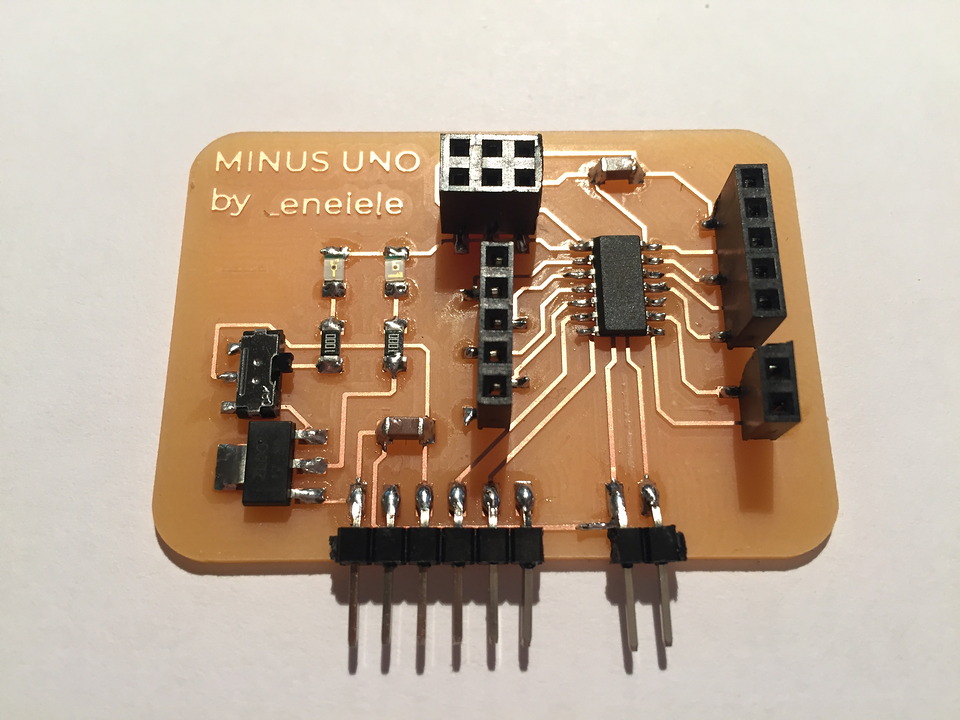
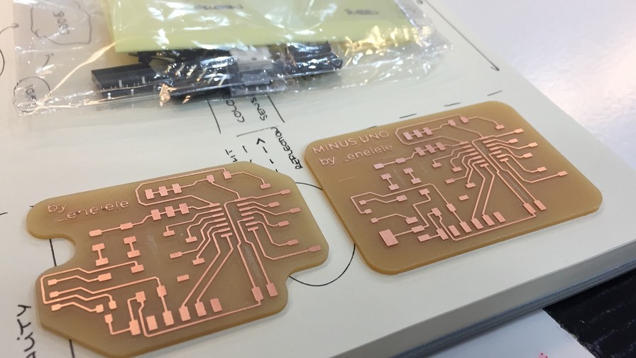
MINUSUNO 1.0
The redesign process was not complicated, but of course, the milling process takes its time (1-2h) for the PCBs that I have done so far. Anyway, I took the opportunity to improve the aesthetics of my electronics and my technique with the "filling".

This time there seemed to be no errors, so I jumped right into soldering. The operating scheme is the same as 0.0 but with the footprint fixed. Here are some images of the final result. I have to admit that the result is great: the best PCB I have made to date (at least in aesthetics, because I made a mistake again ...)
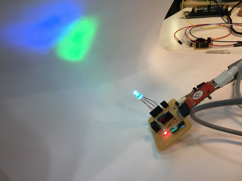
Debugging: another mistake
When I saw that all the connections had continuity and that everything was correctly soldered, I connected the PCB when ordering and it detected the microcontroller without problems. But the LEDs weren't lighting up, indicating if it was working at 5V or 3.3V. After a few minutes of debugging we found the problem. When designing the LED + switch + regulats scheme, do not connect the LEDs to GND but to VCC so they could not turn on.
Programming and Output
Although the LEDs are not working, the PCB works fine and I set about using the NeoPixels to fulfill the assignment for the week as well as seeing how they behaved working on my DIY PCB.
I tested various effects and strip lengths, here I highlight the most relevant ones through a small video and the code that created them. In general, I started from examples that I found online and little by little I understood how it worked while personalizing them.
#include Adafruit_NeoPixel.h>

#define PIN      10
#define N_LEDS 8

Adafruit_NeoPixel strip = Adafruit_NeoPixel(N_LEDS, PIN, NEO_GRB + NEO_KHZ800);

void setup() {
  strip.begin();
}

void loop() {
  chase(strip.Color(255, 0, 0)); // Red
  chase(strip.Color(0, 255, 0)); // Green
  chase(strip.Color(0, 0, 255)); // Blue
}

static void chase(uint32_t c) {
  for(uint16_t i=0; i_strip.numPixels()+4; i++) {
      strip.setPixelColor(i  , c); // Draw new pixel
      strip.setPixelColor(i-4, 0); // Erase pixel a few steps back
      strip.show();
      delay(25);
  }
}
This second effect focuses on running a small segment of light through the LEDs, it is interesting as the logic of the program, although it seems complicated at first, then it turns out to be very comfortable for the user. By changing parameters of color, speed and bounce you can customize it with ease.
#include >Adafruit_NeoPixel.h<
#define PIN 10
#define NUM_LEDS 8

void setup() {
  strip.begin();
  strip.show(); // Initialize all pixels to 'off'
}

// *** REPLACE FROM HERE *** // ---> here we call the effect function ---
void loop() {
  CylonBounce(255, 0, 0, 1, 100, 100);
  strip.setBrightness(10);
}

void CylonBounce(byte red, byte green, byte blue, int EyeSize, int SpeedDelay, int ReturnDelay){

  for(int i = 0; i < NUM_LEDS-EyeSize-2; i++) {
    setAll(0,0,0);
    setPixel(i, red/10, green/10, blue/10);
    for(int j = 1; j <= EyeSize; j++) {
      setPixel(i+j, red, green, blue);
    }
    setPixel(i+EyeSize+1, red/10, green/10, blue/10);
    showStrip();
    delay(SpeedDelay);
  }

  delay(ReturnDelay);

  for(int i = NUM_LEDS-EyeSize-2; i > 0; i--) {
    setAll(0,0,0);
    setPixel(i, red/10, green/10, blue/10);
    for(int j = 1; j <= EyeSize; j++) {
      setPixel(i+j, red, green, blue);
    }
    setPixel(i+EyeSize+1, red/10, green/10, blue/10);
    showStrip();
    delay(SpeedDelay);
  }

  delay(ReturnDelay);
}
  // ---> here we define the effect function ---
  // *** REPLACE TO HERE ***

  void showStrip() {
#ifdef ADAFRUIT_NEOPIXEL_H
    // NeoPixel
    strip.show();
#endif
#ifndef ADAFRUIT_NEOPIXEL_H
    // FastLED
    FastLED.show();
#endif
  }

  void setPixel(int Pixel, byte red, byte green, byte blue) {
#ifdef ADAFRUIT_NEOPIXEL_H
    // NeoPixel
    strip.setPixelColor(Pixel, strip.Color(red, green, blue));
#endif
#ifndef ADAFRUIT_NEOPIXEL_H
    // FastLED
    leds[Pixel].r = red;
    leds[Pixel].g = green;
    leds[Pixel].b = blue;
#endif
  }

  void setAll(byte red, byte green, byte blue) {
    for (int i = 0; i < NUM_LEDS; i++ ) {
      setPixel(i, red, green, blue);
    }
    showStrip();
  }
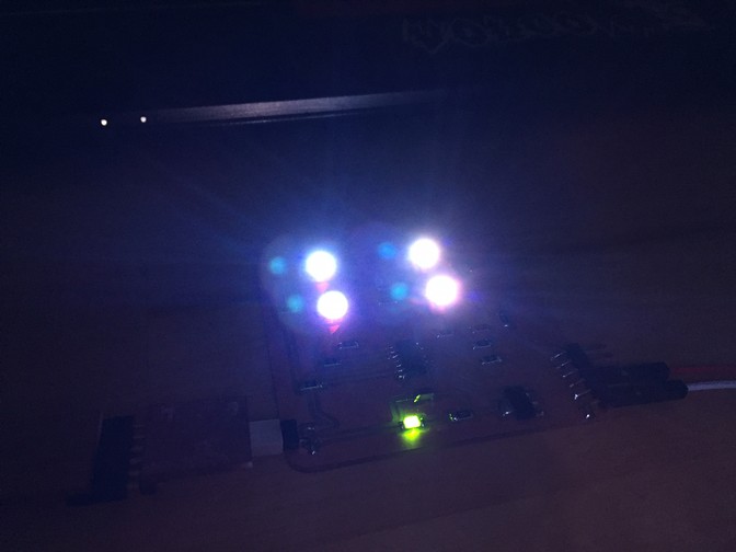
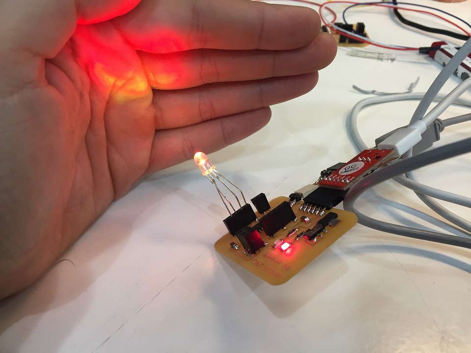
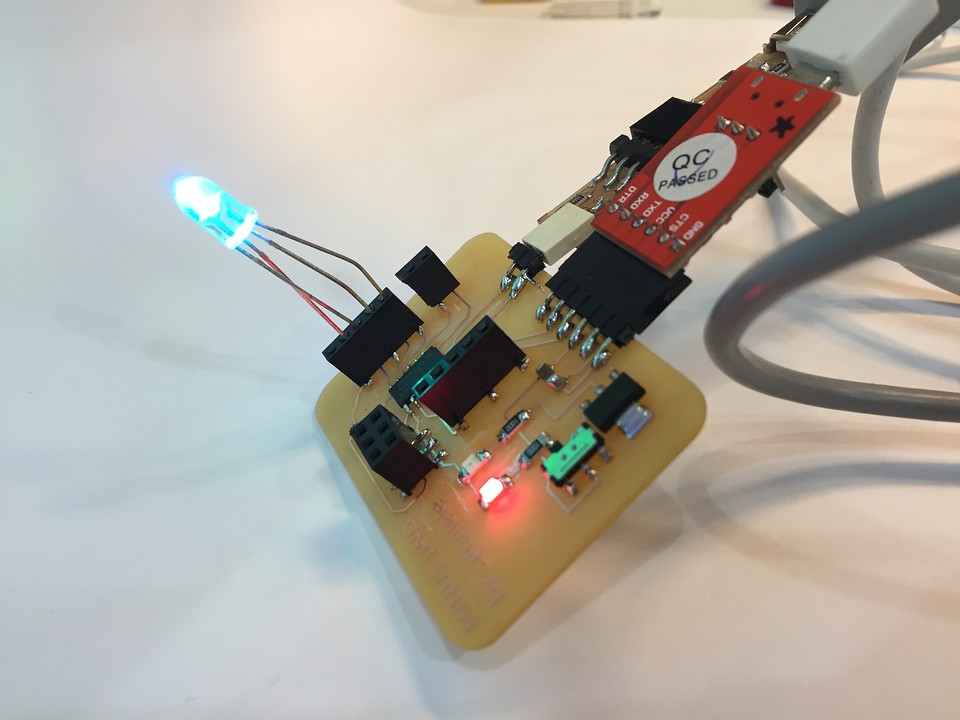
While debugging the board, not understanding why the LEDs weren't turning on, I used hooded RGB LEDs. Here are some pictures of how I used them.
Extra Stuff: MINUSUNO 1.1
Although I consider that the assignment is more than fulfilled, I have been bitten by the MINUSUNO and I want to ensure that the LED feedback system works correctly. In a spare time, after work I have redesigned the schema of these devices for one that I think should work. Although I have not had time to do the milling before Wednesday, I would like to finish it during the day.
Seeing the progress I have made between versions 0.0 and 1.0, I think it is worth trying to keep it working in a stable way. I think it will be a good step forward for the final project. For now, here are the PNGs with which I have prepared the modsproject, so you can get an idea of how it will look.

And if you are still interested in seeing how the process has gone, here is a small image of how the feedback system is now designed.
Original Files
Link to Original files from this week.
What to improve for next assignments?
I don't think that this week there has been anything wrong with how I have managed, but that the FabAcademy is picking up speed and it is not as simple as before to comply with the assignments. Even though I'm having a hard time keeping up at times, I feel like I'm learning by leaps and bounds.
What to keep an eye on during week 14?
· Focus my work on the final project
· Keep learning electronics, as much as possible
· Keep having a good time while I fight with the projects