Week 14:
Networking and communications
This week can be interesting, because we are going to see how to communicate different electronic systems between them. I think that's where the power of the PCBs we've designed during the electronics weeks really comes in.
I have a feeling that it is at the time that data moves through devices that we can really say that all this electronics has usefulness. Perhaps that statement is too broad: I mean that in the movement of data between devices you find the great power of computing and electronics.
My color sensor works by I2C bus so I hope this week will be useful to get to the first iteration of my final project, at least in the electronic aspects.
The assignments for this week are:
Group assignment:
• Send a message between two projects
Individual assignment:
• Design, build, and connect wired or wireless node(s) with network or bus addresses
Group assignments
This week I could not agree with my colleagues to do the assignment group experience so I did it by myself using an Arduino UNO and my ATTiny1614.
You will find the same information of the group assignment a little further down the web, but I prefer to place it here too so that the group assignment is complete.
I2C Scanning
For this experience use the following materials:
- Arduino UNO
- VEML Breakout board
- Hook-up wires
The goal is to discover the unique address of the VEML6040 sensor
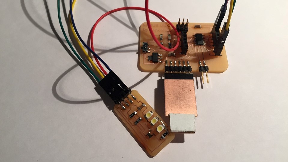
I prepare the connections between the arduino and my breakout board
For the code I use the Z-HUT tutorial that I found in the following link
// ————————————–
// i2c_scanner
//
// Version 1
// This program (or code that looks like it)
// can be found in many places.
// For example on the Arduino.cc forum.
// The original author is not know.
// Version 2, Juni 2012, Using Arduino 1.0.1
// Adapted to be as simple as possible by Arduino.cc user Krodal
// Version 3, Feb 26 2013
// V3 by louarnold
// Version 4, March 3, 2013, Using Arduino 1.0.3
// by Arduino.cc user Krodal.
// Changes by louarnold removed.
// Scanning addresses changed from 0…127 to 1…119,
// according to the i2c scanner by Nick Gammon
// https://www.gammon.com.au/forum/?id=10896
// Version 5, March 28, 2013
// As version 4, but address scans now to 127.
// A sensor seems to use address 120.
// Version 6, November 27, 2015.
// Added waiting for the Leonardo serial communication.
//
//
// This sketch tests the standard 7-bit addresses
// Devices with higher bit address might not be seen properly.
//

#include <'Wire.h>

void setup()
{
Wire.begin();

Serial.begin(9600);
while (!Serial); // Leonardo: wait for serial monitor
Serial.println("\nI2C Scanner");
}

void loop()
{
byte error, address;
int nDevices;

Serial.println("Scanning…");

nDevices = 0;
for(address = 1; address < 127; address++ )
{
// The i2c_scanner uses the return value of
// the Write.endTransmisstion to see if
// a device did acknowledge to the address.
Wire.beginTransmission(address);
error = Wire.endTransmission();

if (error == 0)
{
Serial.print("I2C device found at address 0x");
if (address<'16)
Serial.print("0");
Serial.print(address,HEX);
Serial.println(" !");

nDevices++;
}
else if (error==4)
{
Serial.print("Unknown error at address 0x");
if (address<'16)
Serial.print("0");
Serial.println(address,HEX);
}
}
if (nDevices == 0)
Serial.println("No I2C devices found\n");
else
Serial.println("Done!");

delay(5000); // wait 5 seconds for next scan
}
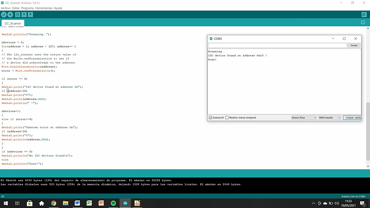
Everything worked fine the first time, not without some changes in the code, but in general we can say that it was a "first try". Here below I leave you a screenshot so you can check what I tell you and see the direction of the sensor.
I2C Master & Slave
Now is the time to actually generate inter-microcontroller communication with I2C. For this I will use:
- Arduino UNO
- MINUSUNO 1.1
- Hook-up wires
The first step is to find the SCL and SDA pins of my MINUSUNO and their translation to pin number.
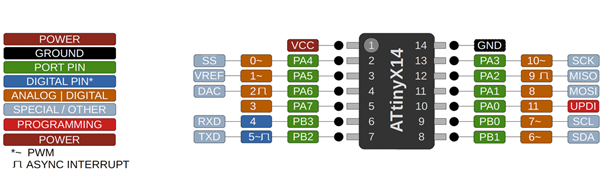
- SCL: pin number 7
- SDA: pin number 6
The second step is to find the SCL and SDA pins of the Arduino UNO. They are clearly labelled but I need the number for the code.
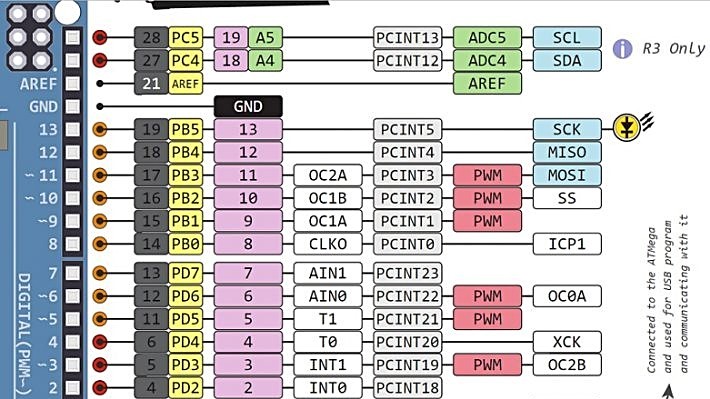
- SCL: pin number A5/19
- SDA: pin number A4/18
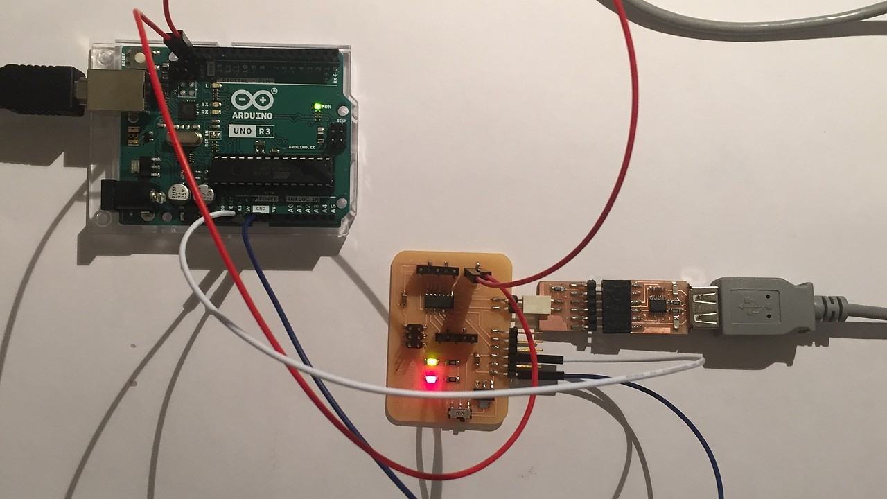
We continue with the wired connections between the boards and the computer. Leaving everything prepared like this for the codes.
Code for Master / receiver (Arduino):
#include

void setup() {
  Wire.begin();        // join i2c bus (address optional for master)
  Serial.begin(9600);  // start serial for output
}

void loop() {
  Wire.requestFrom(8, 6);    // request 6 bytes from slave device #8

  while (Wire.available()) { // slave may send less than requested
    char c = Wire.read();    // receive a byte as character
    Serial.print(c);         // print the character
  }

  delay(500);
}
Code for Slave / sender (ATtiny1614):
#include

void setup() {
    Wire.begin(8);                // join i2c bus with address #8
    Wire.onRequest(requestEvent); // register event
}

void loop() {
    delay(100);
}

// function that executes whenever data is requested by master
// this function is registered as an event, see setup()
void requestEvent() {
    Wire.write("_nil_"); // respond with message of 6 bytes
    // as expected by master
}
I have to understand who was Slave and who was Master to upload the corresponding codes. Once the doubts have been solved, everything works correctly and the two boards are communicating without problems. Watch the following video to see the prints of the serial monitor.
Individual Assignment
As I mentioned a little above, the idea of this week is to finally use the VEML6040 sensor (it has finally arrived at the LAB !!, we'll actually is been here for a week but I wasn't ready to use it .. .). The idea for this week is to put it to work hand in hand with the MINUSUNO who I think will be finished in this third iteration.
MINUSUNO 1.1
As I told you last week, I made a mistake in that the feedback LEDs (5V or 3.3V) were connected as a direct consumption of the ATTINY1614's VCC, so they did not glow correctly and were reducing the power of the microcontroller.
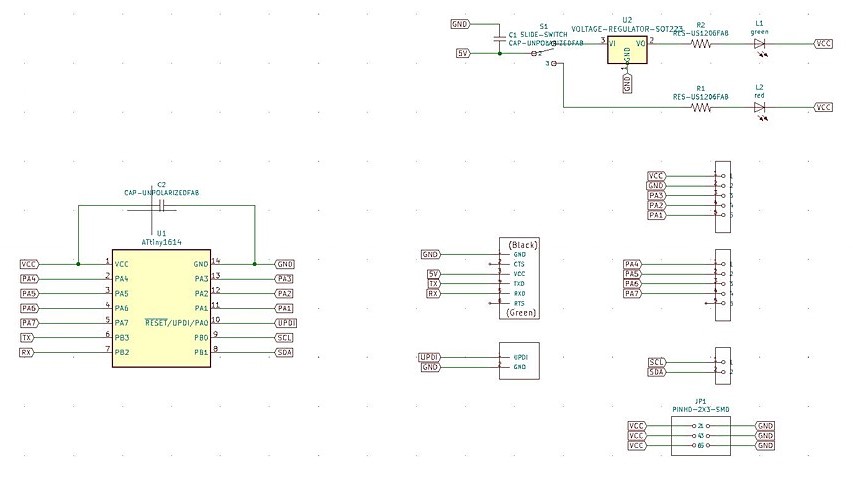
In the following images you have the schematics of MINUSUNO 1.0 and right next to it the redesigned LED system.
As it is not a relevant change I prefer to pass this point quickly, to focus on the VEML6040 which is what has really occupied me this week. The LEDs are an add-on that I want to solve but that does not seriously affect the operation of the PCB. Yes, let's look at how the milling was. Also the design was prepared last week, but I didn't get to do the milling before Wednesday.
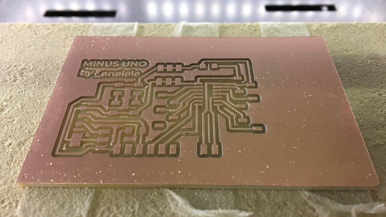
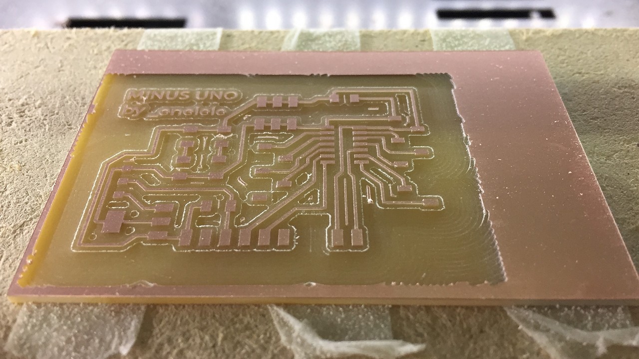
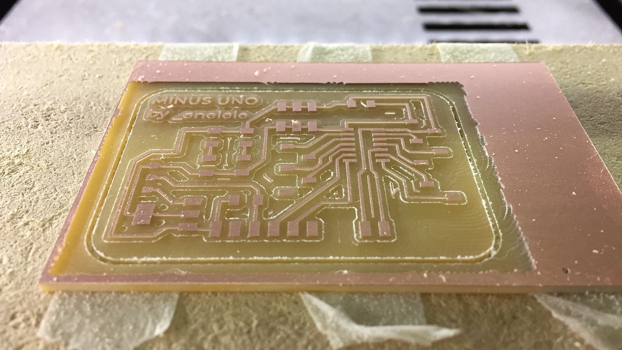
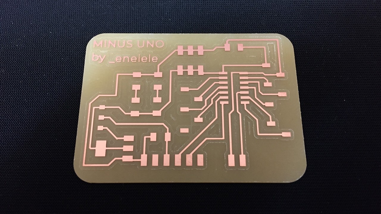
Milling
I have to say that I love the miling process in 3 steps! I think the PCBs look great and are also easier to see as the paths are so clear.
Soldering
The soldering process no longer has secrets for me in the MINUSUNO, because it is the third time I have done it. The only change I will make is to change the VCC and GND sockets to 2x3 headers. I have noticed that most PCBs mix both systems to avoid incompatibilities due to lack of cables or similar. I will also take the opportunity to reverse the direction of the button, which I soldered incorrectly last time.
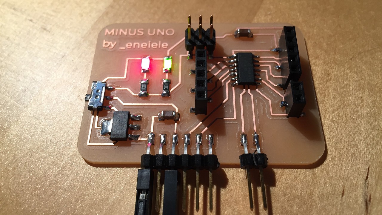
Yet another mistake
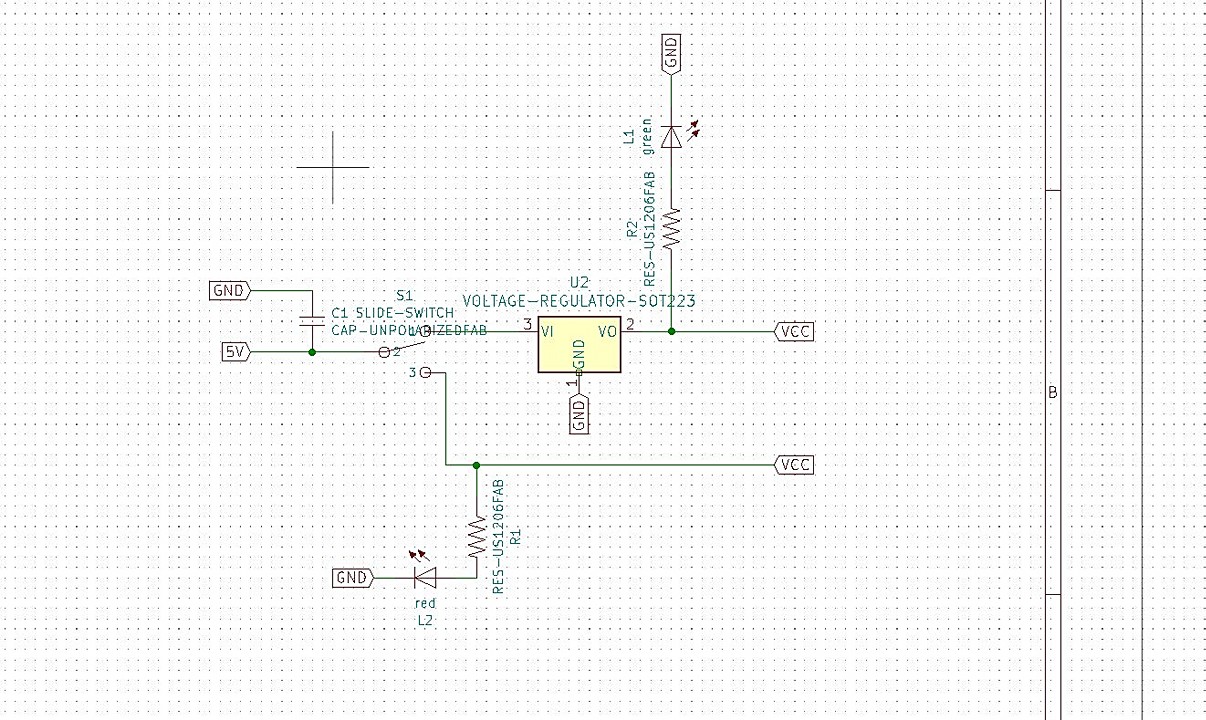
If you look at the schematics and the image you have above where the LEDs are lit: I HAVE DESIGNED THE FEEDBACK SYSTEM BETWEEN 5V AND 3.3V WRONG.
I'm starting to believe that this system hates me. Checking the schematichs I see that the design is correct, but when I looked at the tracing I realized that the VCC connections (which must be joined together) are incorrectly connected. That is why both LEDs light up at the same time. Both come from the same input and go to GND, therefore both will always be on, regardless of the position of the switch.
COLOR SENSOR: VEML6040
In previous weeks I already told you about this sensor, so I am not going to go into too deep technical details. So that you understand how it works, this sensor simultaneously reads the following parameters:
- RED
- GREEN
- BLUE
- WHITE
- CCT (Correlated Color Temperature)
- AL (Ambient Light)
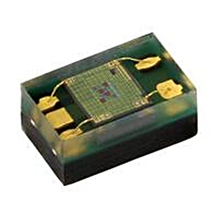
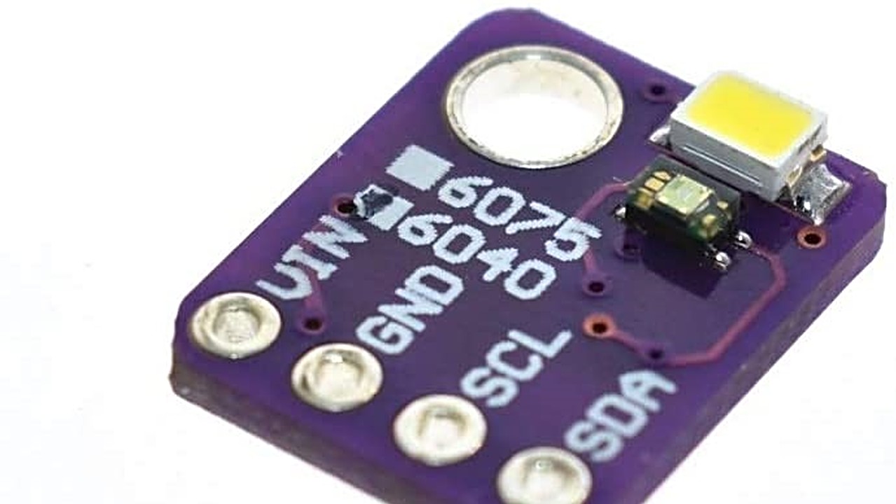
As you can see in the previous images, the manufacturer himself already raises the sensor as a breakout for Arduino or similar PCBs. In my case and assuming that the MinusUNO is my homemade open pin PCB, I think it is the best way to approach the design of this sensor.
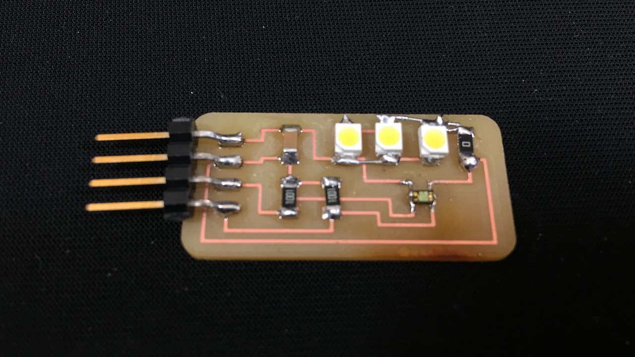
Breakout Design
Before starting the design process I had to take into account many technical notes found in the datasheet. Below you have a small table of the values that should be taken into account.
- Max Voltage: 3.7V
- I2C pullup resistor: 1kΩ between SDA_VCC and SCL_VCC
- Capacitor: 0.1uF between GND and VCC
- Light Source: 3 high emmiting white LED
Check out all the information about the Vishay VEML6040 in the great post I found on GitHub. You will find all the information necessary to work with this sensor, from images to code and datasheets.
Turning now to Kicad's schematics, I have to admit that it was straightforward compared to microcontroller PCBs. The breakout modules are simple and have not caused many problems.
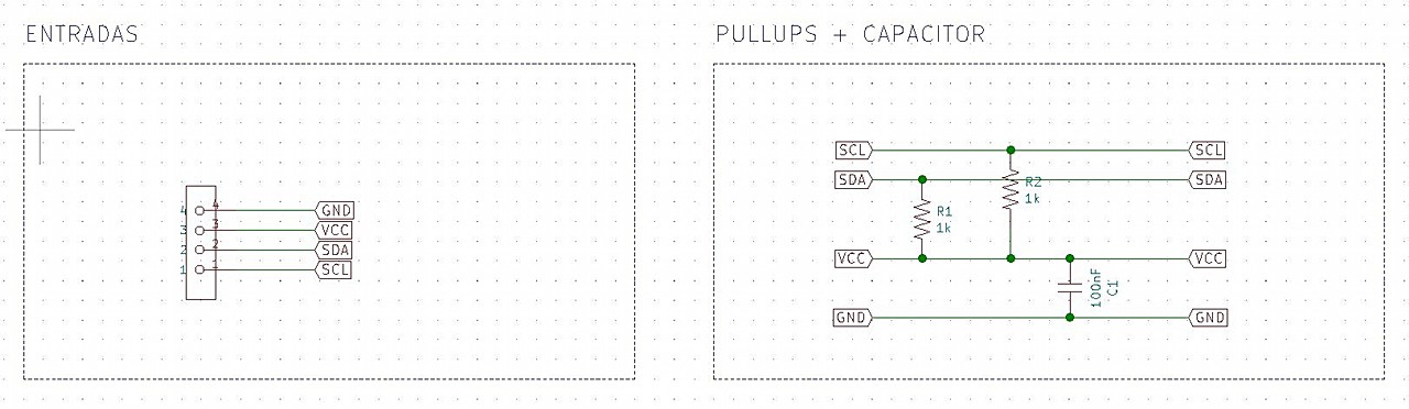
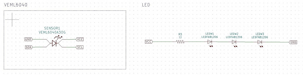
The same thing happens with footprints, but an added difficulty appears. The sensor's schematics and footprint are not found in the Kicad libraries and I had to find them in online forums. In my case I found it in Ultra Librarian, although anyway I had to make corrections because the symbol was wrong.
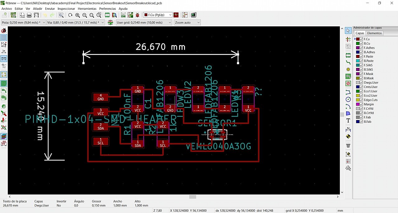
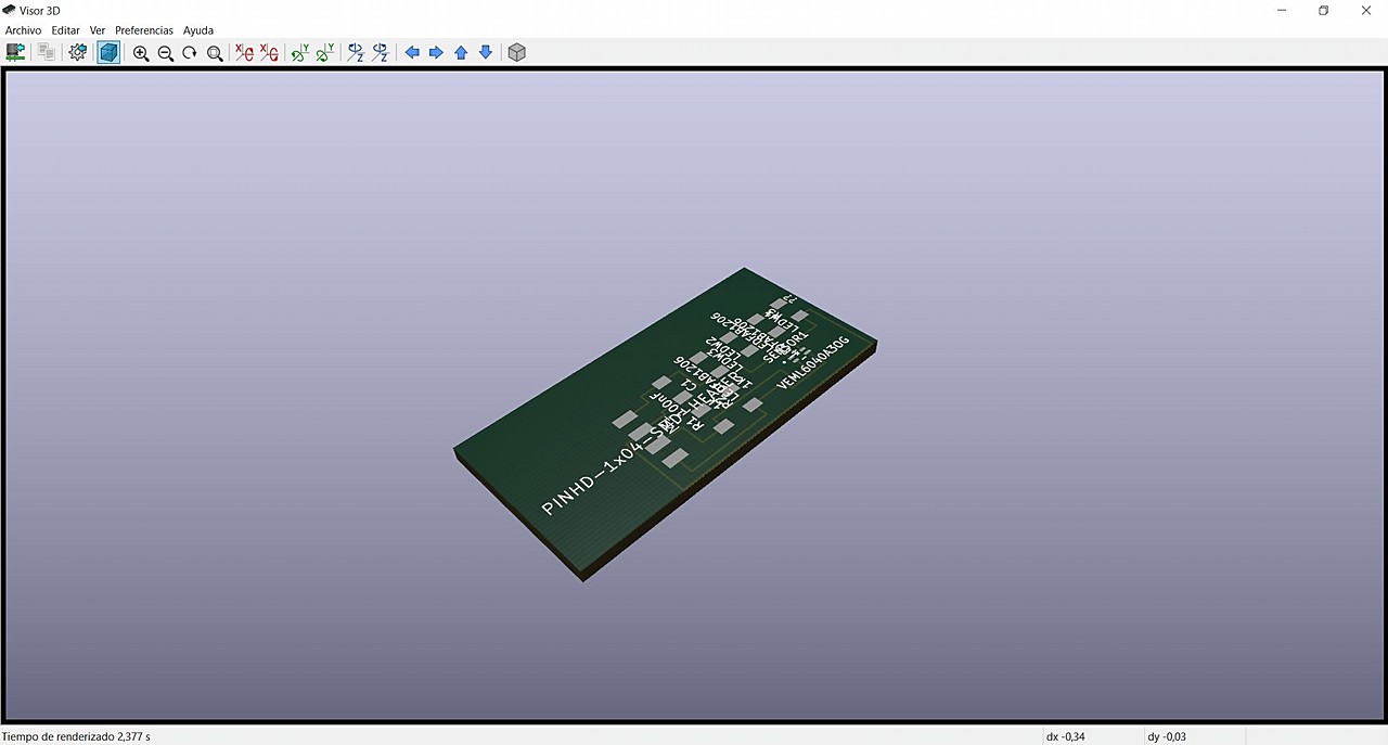
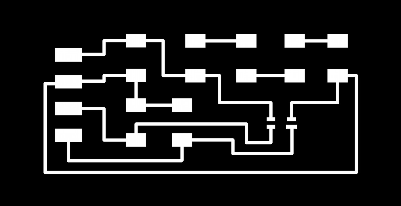
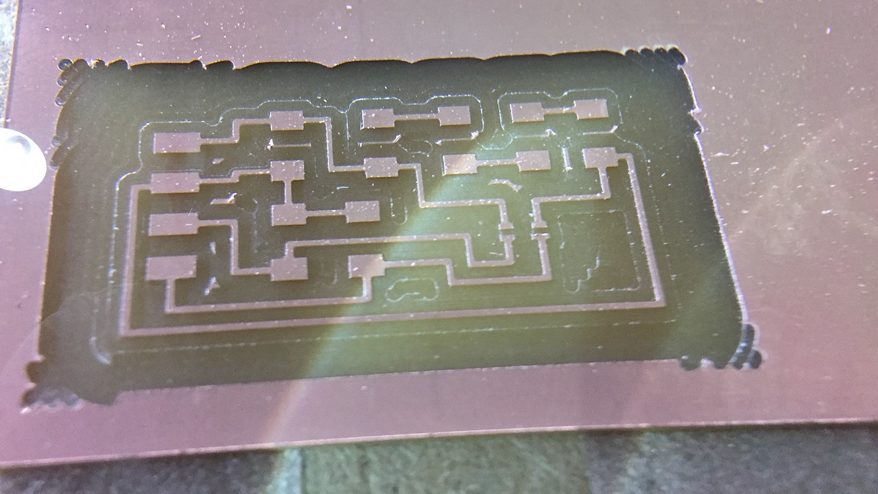
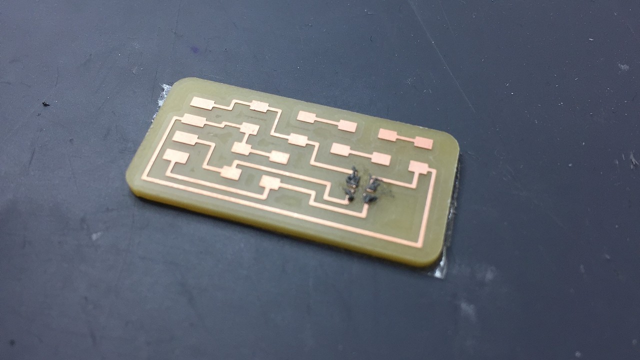
Breakout Milling
I think the milling process of this PCB is the most difficult I have done so far. When I learned to work in 3 steps I already considered that my milling game was good, but with this footprint it is another story. The small 1/64 "bit is too big to fit inside the VEML pads. So it was necessary to work on the following 4 steps:
- Tracing: 1/64" at 4mm/s
- Filling: 1/32" at 4mm/s
- Detailing (Veml Footprint): 0.010" at 0.2mm/s
- Cutting: 1/32" at 1.5mm/s
The process has been short, because the size of the breakout is reduced, but you have to have three changes of endmill and three changes of origin in the Z axis. Here are the pngs that I used in Mods Project.

And here you have the step by step of how the results of each of the previous g-code files were being:
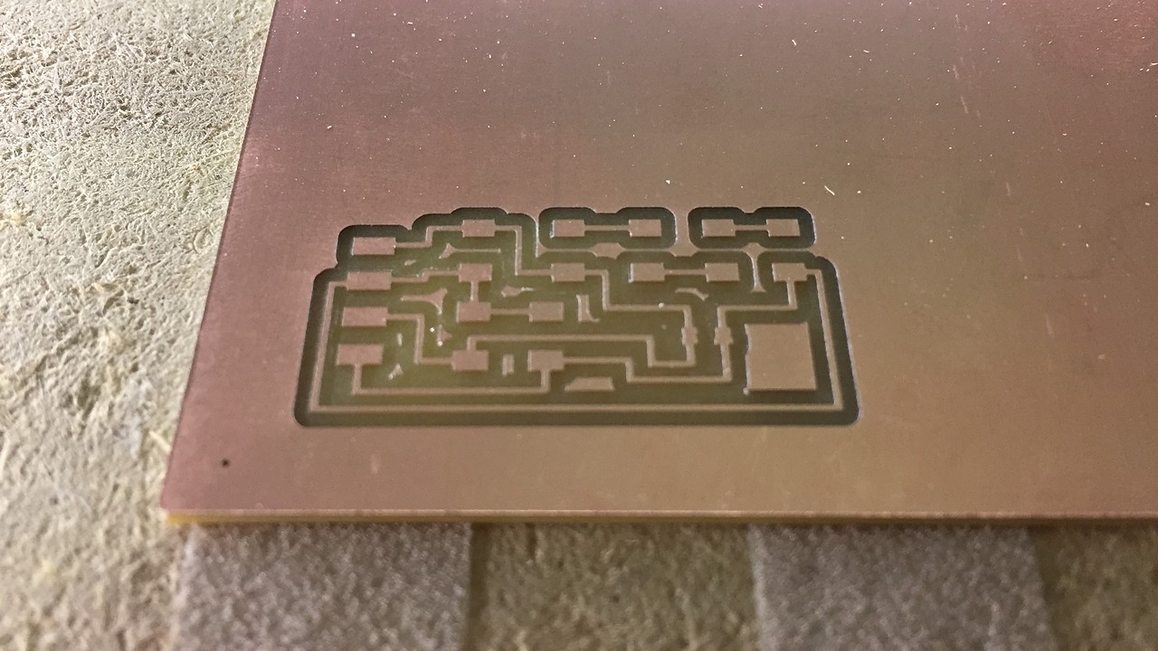
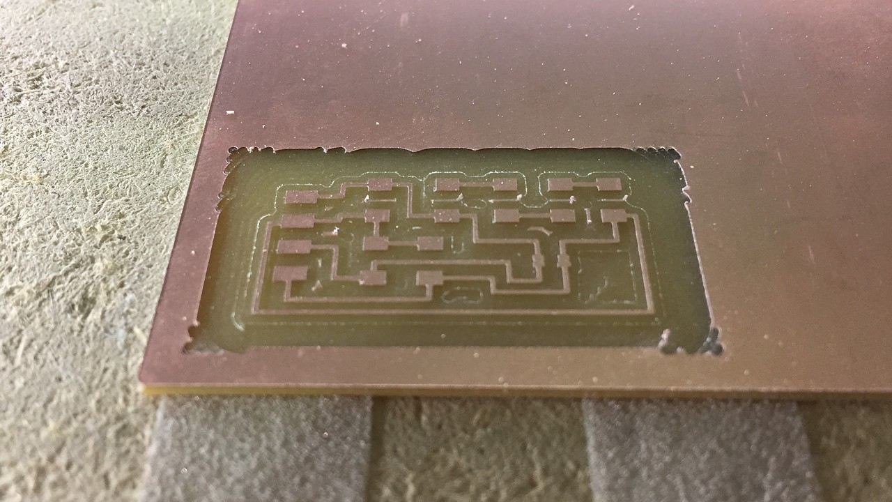
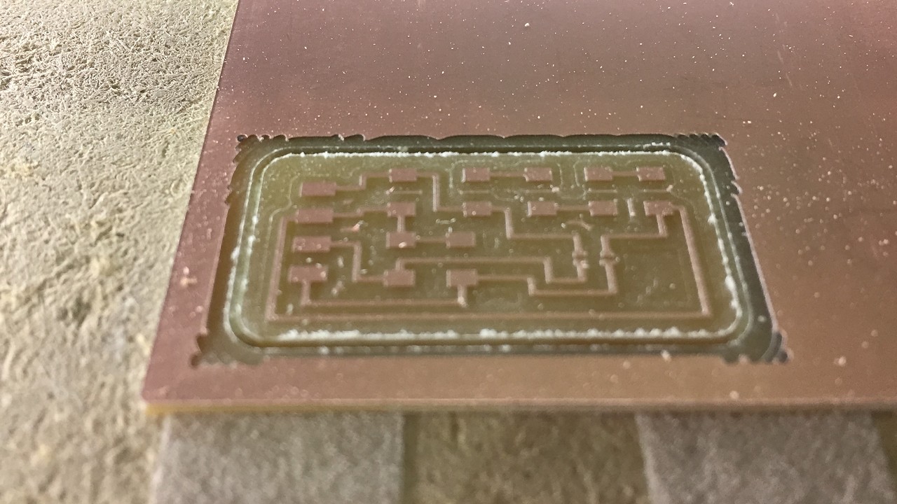
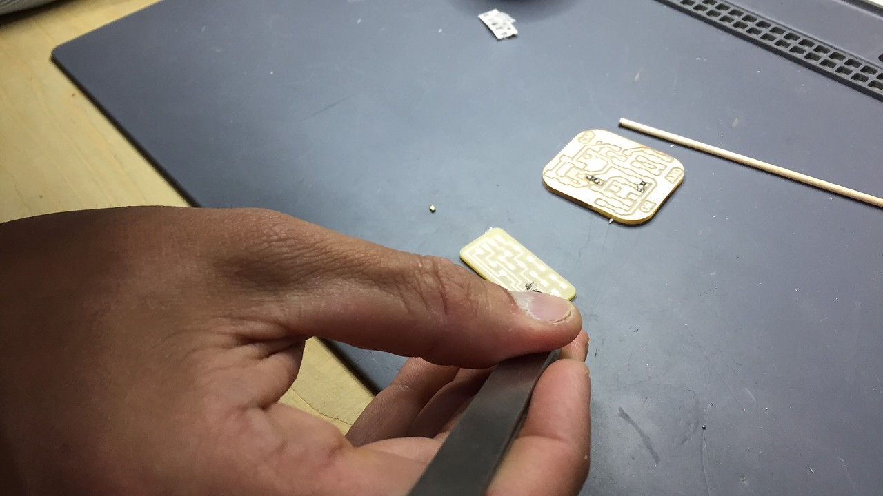
The footprint is so small that I had to use a x10 magnifying lens to check that the endmill had cut the pads for the sensor correctly. (If you look at the third image, I had to use it to take the photo haha).
Anyway, the results are great and I am more than happy with how much I have improved at the CNC. I think it's one of the things I've liked the most about FabAcademy so far.
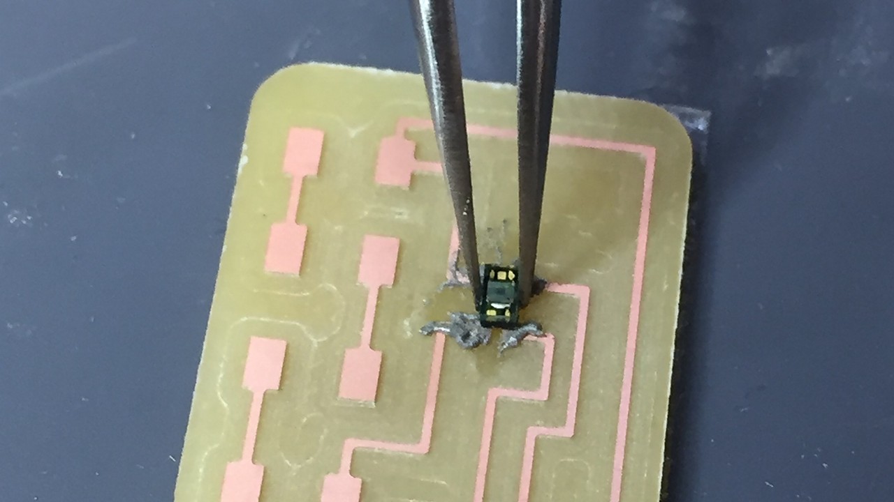
Breakout Soldering
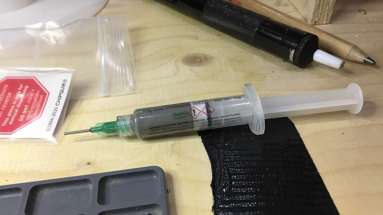
If milling wasn't complex enough, now was the time to solder the components in place. All are simple except the VEML6040, this has to be soldered by reflow, by hand it is almost impossible. So there I had to ask my instructors for help. Edu taught me to work with reflow and between the two of us we managed to solder it correctly. For the future, I am going to make a little step-by-step guide to remember the steps if I have to use it later.
STEP 1: read the datasheet and prepare the soldering paset syringe This is a highly toxic product so we did all the process following the safety sheet. Apart from that, we avoid contact with the skin, we wear a mask and we keep the workspace well ventilated by means of a carbon filter.
STEP 2: Apply the soldering paste and clean the excess with care and a wooden toothpick.This process is not difficult, but we needed the help of the x10 lens to be able to make sure not to break the pads and that the paste was on top of them.
STEP 3: check the temperture curve for veml6040 and apply heat with the heatgun This is the really complicated process. PCB components and especially optical ones are easy to burn because they are very sensitive to temperature. Luckily Edu was with me throughout the process, because I still burned the resin that holds the copper.
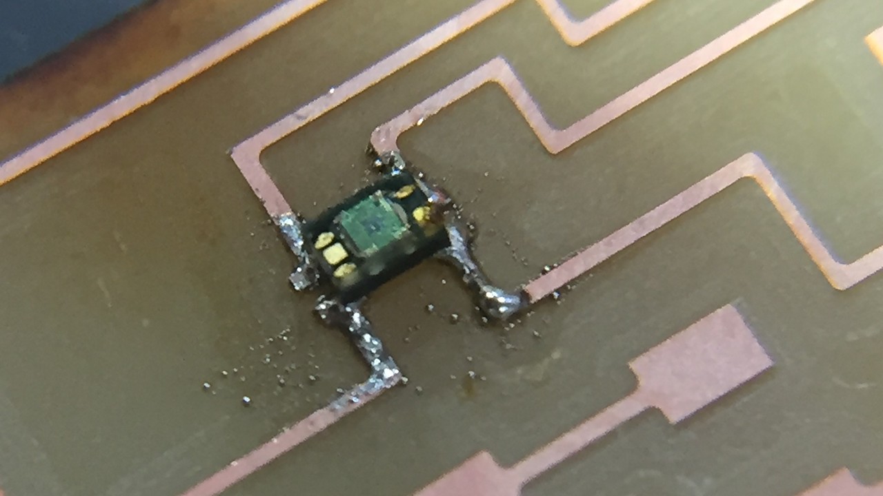
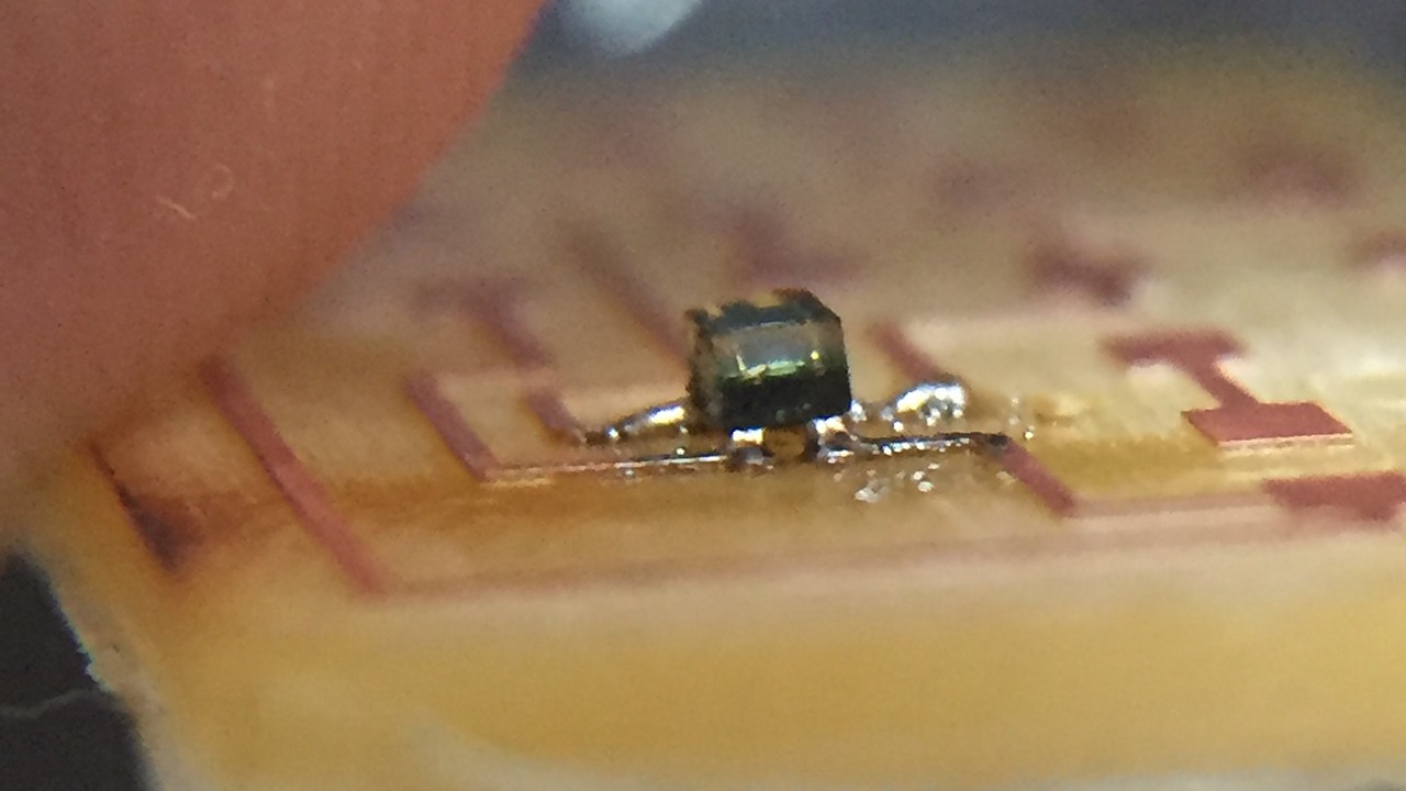
Finally, here you have a small video of how the component was soldered by reflow. I recommend that you listen to it with sound: you can feel the panic in our voices.
The rest of the components were not a problem, because these can be welded by hand without difficulties. Anyway, there was a problem. I had made the calculations for the LEDs to work in series, but it was not possible due to the low voltage at which the breakout works. Using a little cable and inventiba we managed to make them work in parallel (and the whole arrangement was quite disguised).
I2C Communication
Before proceeding with the communication that I have to do in my final project (veml6040-attiny1614) I want to understand the basics of I2C communication. For that I want to do some experiences with this system. I also think it is a good way to understand if the sensor and the MINUSUNO board are working properly.
I2C Scanning
For this experience use the following materials:
- Arduino UNO
- VEML Breakout board
- Hook-up wires
The goal is to discover the unique address of the VEML6040 sensor
I prepare the connections between the arduino and my breakout board
For the code I use the Z-HUT tutorial that I found in the following link
// ————————————–
// i2c_scanner
//
// Version 1
// This program (or code that looks like it)
// can be found in many places.
// For example on the Arduino.cc forum.
// The original author is not know.
// Version 2, Juni 2012, Using Arduino 1.0.1
// Adapted to be as simple as possible by Arduino.cc user Krodal
// Version 3, Feb 26 2013
// V3 by louarnold
// Version 4, March 3, 2013, Using Arduino 1.0.3
// by Arduino.cc user Krodal.
// Changes by louarnold removed.
// Scanning addresses changed from 0…127 to 1…119,
// according to the i2c scanner by Nick Gammon
// https://www.gammon.com.au/forum/?id=10896
// Version 5, March 28, 2013
// As version 4, but address scans now to 127.
// A sensor seems to use address 120.
// Version 6, November 27, 2015.
// Added waiting for the Leonardo serial communication.
//
//
// This sketch tests the standard 7-bit addresses
// Devices with higher bit address might not be seen properly.
//

#include <'Wire.h>

void setup()
{
Wire.begin();

Serial.begin(9600);
while (!Serial); // Leonardo: wait for serial monitor
Serial.println("\nI2C Scanner");
}

void loop()
{
byte error, address;
int nDevices;

Serial.println("Scanning…");

nDevices = 0;
for(address = 1; address < 127; address++ )
{
// The i2c_scanner uses the return value of
// the Write.endTransmisstion to see if
// a device did acknowledge to the address.
Wire.beginTransmission(address);
error = Wire.endTransmission();

if (error == 0)
{
Serial.print("I2C device found at address 0x");
if (address<'16)
Serial.print("0");
Serial.print(address,HEX);
Serial.println(" !");

nDevices++;
}
else if (error==4)
{
Serial.print("Unknown error at address 0x");
if (address<'16)
Serial.print("0");
Serial.println(address,HEX);
}
}
if (nDevices == 0)
Serial.println("No I2C devices found\n");
else
Serial.println("Done!");

delay(5000); // wait 5 seconds for next scan
}
Everything worked fine the first time, not without some changes in the code, but in general we can say that it was a "first try". Here below I leave you a screenshot so you can check what I tell you and see the direction of the sensor.
I2C Master & Slave
Now is the time to actually generate inter-microcontroller communication with I2C. For this I will use:
- Arduino UNO
- MINUSUNO 1.1
- Hook-up wires
The first step is to find the SCL and SDA pins of my MINUSUNO and their translation to pin number.
- SCL: pin number 7
- SDA: pin number 6
The second step is to find the SCL and SDA pins of the Arduino UNO. They are clearly labelled but I need the number for the code.
- SCL: pin number A5/19
- SDA: pin number A4/18
We continue with the wired connections between the boards and the computer. Leaving everything prepared like this for the codes.
Code for Master / receiver (Arduino):
#include

void setup() {
  Wire.begin();        // join i2c bus (address optional for master)
  Serial.begin(9600);  // start serial for output
}

void loop() {
  Wire.requestFrom(8, 6);    // request 6 bytes from slave device #8

  while (Wire.available()) { // slave may send less than requested
    char c = Wire.read();    // receive a byte as character
    Serial.print(c);         // print the character
  }

  delay(500);
}
Code for Slave / sender (ATtiny1614):
#include

void setup() {
    Wire.begin(8);                // join i2c bus with address #8
    Wire.onRequest(requestEvent); // register event
}

void loop() {
    delay(100);
}

// function that executes whenever data is requested by master
// this function is registered as an event, see setup()
void requestEvent() {
    Wire.write("_nil_"); // respond with message of 6 bytes
    // as expected by master
}
I have to understand who was Slave and who was Master to upload the corresponding codes. Once the doubts have been solved, everything works correctly and the two boards are communicating without problems. Watch the following video to see the prints of the serial monitor.
VEML 6040 PROGRAMMING
This time I go back to doing a huge shoutout to Adrián Torres from FabLabLeon. He had used one of these color sensors and the code he made is more than intuitive. To be the first test of how the sensor reads colors the truth is that it is a great code.
As it is not micro-controlled, the VEML6040 is not programmed but rather the I2C bus is used as a communication channel between the sender (sensor) and the receiver (ATtiny1614). Therefore, programming is always carried out from the MINUSUNO.
The Adrián code that I have used is the following:
//Fab Academy 2021 - Fab Lab León
//Color
//Adrianino
//ATtiny1614

#include "Wire.h"
#include "veml6040.h"

VEML6040 RGBWSensor;
int r,g,b,w;

void setup() {
  Serial.begin(115200);
  Wire.begin();

  if(!RGBWSensor.begin()) {
    Serial.println("ERROR: couldn't detect the sensor");
    while(1){}
  }

  /*
   * init RGBW sensor with:
   *  - 320ms integration time
   *  - auto mode
   *  - color sensor enable
   */

  RGBWSensor.setConfiguration(VEML6040_IT_320MS + VEML6040_AF_AUTO + VEML6040_SD_ENABLE);

  delay(1500);
  Serial.println("Vishay VEML6040 RGBW color sensor auto mode example");
  Serial.println("CCT: Correlated color temperature in \260K");
  Serial.println("AL: Ambient light in lux");
  delay(1500);

}

void loop() {

  r = RGBWSensor.getRed();
  g = RGBWSensor.getGreen();
  b = RGBWSensor.getBlue();
  w = RGBWSensor.getWhite();


  Serial.print(r);
  Serial.print(",");
  Serial.print(g);
  Serial.print(",");
  Serial.print(b);
  Serial.print(",");
  Serial.println(w);
 }
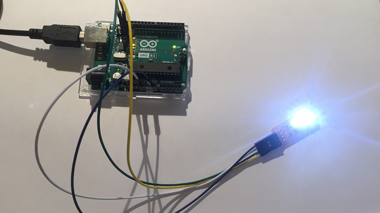
The compilation worked on the first try and without any problem the sensor started reading. Specifically, the values that it returns with the previous code are R, G, B, AL in that order. To read the information and through the RX / TX port I got the following readings in front of a blue object.
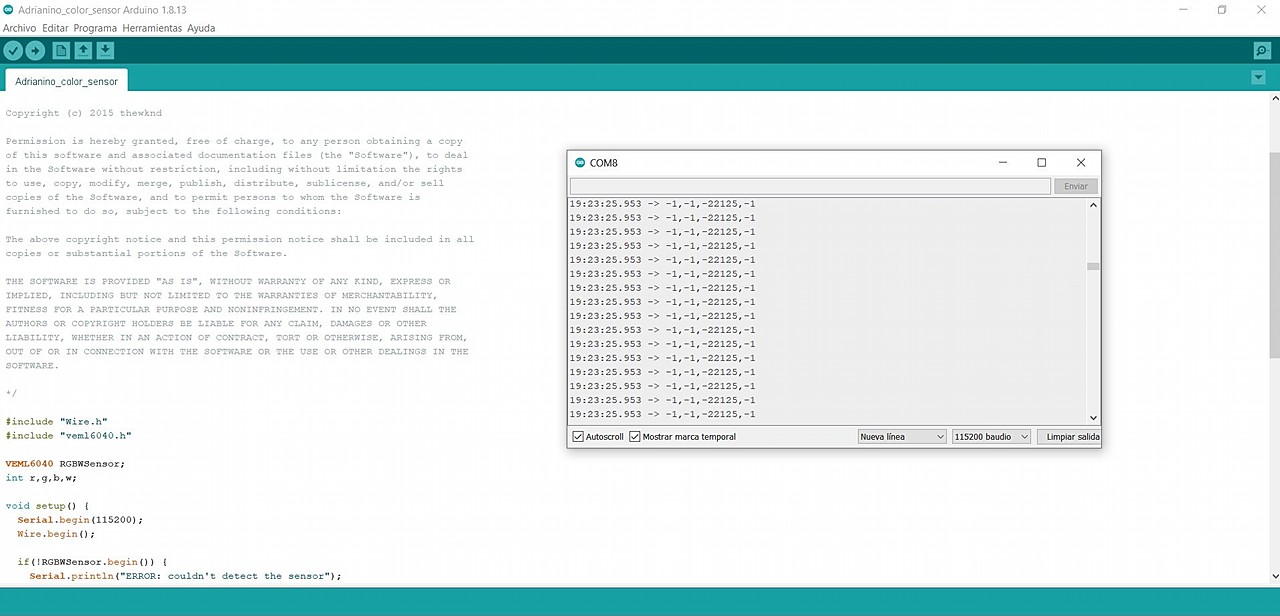
Sensor calibration work will be necessary to make data processing more controllable than it is currently. But anyway I am happy with the result !!
EXTRA: PROCESSING
Reading the data through numerical values, I find it somewhat uncomfortable although they give a good feeling of how the value changes. Investigating a bit I found that with processign it was possible to make real-time graphs of the data that the sensor received.
I don't know much about the Processing program but thanks again to Adrian I managed to graph the data from the VEML6040. The graphing data jumps directly to processing through the serial data monitor (RX / TX). The following code converts the data received through the serial port to a R, G, B, AL bar graph.
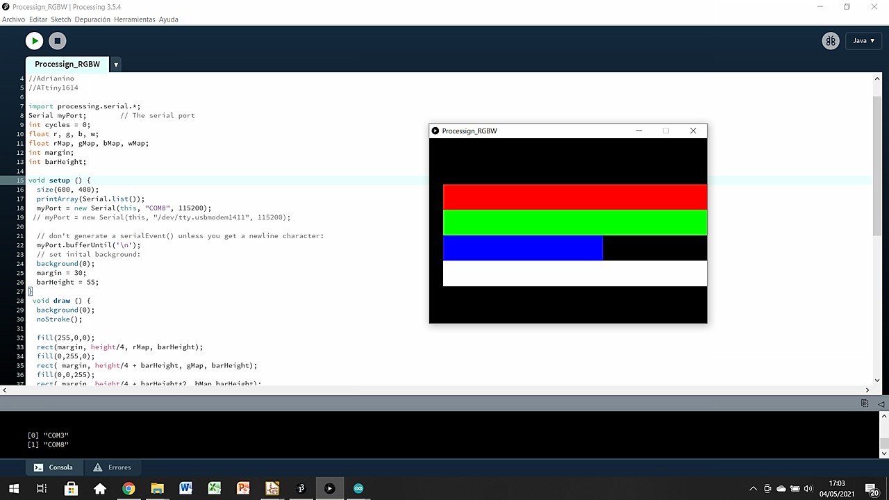
Soon I would like to show you a short video seeing how these bars move based on the ambient light and the color that the sensor reads, but I have not had time so far. I hope that being extra content, it is not a problem.
Here is the processign code that I have used.
//Fab Academy 2021 - Fab Lab León
//Adrián Torres & Marta Verde
//Color
//Adrianino (Thank god we have Adrian around!)
//ATtiny1614

import processing.serial.*;
Serial myPort;        // The serial port
int cycles = 0;
float r, g, b, w;
float rMap, gMap, bMap, wMap;
int margin;
int barHeight;

void setup () {
  size(600, 400);
  printArray(Serial.list());
  myPort = new Serial(this, "COM8", 115200);
 // myPort = new Serial(this, "/dev/tty.usbmodem1411", 115200);

  // don't generate a serialEvent() unless you get a newline character:
  myPort.bufferUntil('\n');
  // set inital background:
  background(0);
  margin = 30;
  barHeight = 55;
}
 void draw () {
  background(0);
  noStroke();

  fill(255,0,0);
  rect(margin, height/4, rMap, barHeight);
  fill(0,255,0);
  rect( margin, height/4 + barHeight, gMap, barHeight);
  fill(0,0,255);
  rect( margin, height/4 + barHeight*2, bMap,barHeight);
  fill(255);
  rect(margin, height/4 + barHeight*3, wMap, barHeight);
  /*
  if (cycles >= 10) {
    cycles = 0;
    background(0);
   }
   cycles++;
   */
 }

void serialEvent(Serial myPort) {
  String inString = myPort.readStringUntil('\n');
  if (inString != null) {
    inString = trim(inString);
    int[] data = int(split(inString, ",")); //se parte el mensaje con las comas
    if (data.length >=4) { //este numero, poner cuantos mensajes se esperan
      r = int(data[0]);
      g = int(data[1]);
      b = int(data[2]);
      w = int(data[3]);

      rMap = map(r, 0, 6000, 0, height);
      gMap = map(g, 0, 6000, 0, height);
      bMap = map(b, 0, 6000, 0, height);
      wMap = map(w, 0, 6000, 0, height);
    }
  }
}
Original Files
Link to Original files from this week.
What to improve for next assignments?
.his week we found out that we have to present the final project on June 9th. So I think the time has come to sacrifice weekly assignments before developing the project. Obviously I will continue doing them, and attending classes, but the difficulty that I apply in these is going to be greatly reduced.
What to keep an eye on during week 15?
· Final Porject, Final Porject, Final Project...
· Try to use a project management software to keep an eye on timmings.
· Keep having a good time while I fight with the project.