Week 4:
Electronics production
This week looks promising, electronic production. We will be going through the main steps of building your own electronic PCB. If already worked with this kind of workspaces for electronic development, but never with this much depth.
I more or less understand the electrical principles involved in electronic devices, but sincerely not that well. I believe this week may allow me to learn a lot more on this topic and be able to design my own PCB. Until the moment I always had the feeling that I was more of a user, rather than a designer.
The three assignments for this week are:
Group assignment:
• Characterize the design rules for your PCB production process.
Individual assignment:
• Make an in-circuit programmer by milling and stuffing the PCB,test it.
• Then optionally try other PCB processes.
Group Assignment
The first thing to do this week was to understand the working of CNC machines. Learn how to use the Mods and ModsProject software, characterize all the settings and check te CNC performance in climb and conventional mode. To have a better look at what we did I’m going to split this chapter into the following lower chapter:
- Mods vs. ModsProject
- Roland SRM-20 vs. G-code CNC
- Climb vs. Conventional
Just to get started, let’s jump into comparing the softwares.
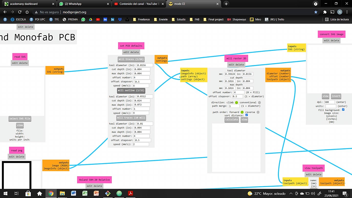
Mods vs. ModsProject
Both this softwares were developed to parameterize the PCB png files, and be able to ride them from the milling machine. The major differences are on the User Inteface and the way you interact with the software. My personal opinion is that for a super noob user like me, ModsProject is going to be way easier. But let’s see how both of them work.
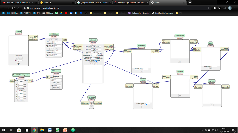
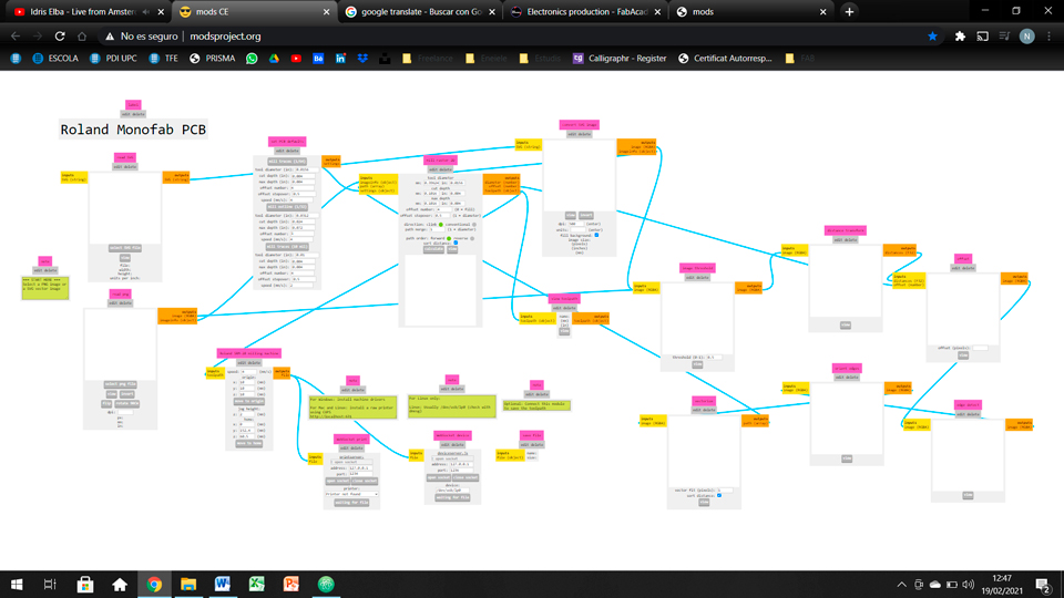
Focusing into the UI, I believe ModsProject offers a way more user-friendly experience. Maybe it is for the color choice or maybe the spaces created between the blocks, but I feel it way more engaging. On the other side, Mods feel a bit older and not so nice to work with.
By sacrificing some minor settings, the community has developed a software more based in the use, rather than the super complex feeling that Mods transmits. I think not many changes have been sacrificed (for example, the possibility to change between mm/s and mm/min), but the ones that have I think are more focused on experienced users.
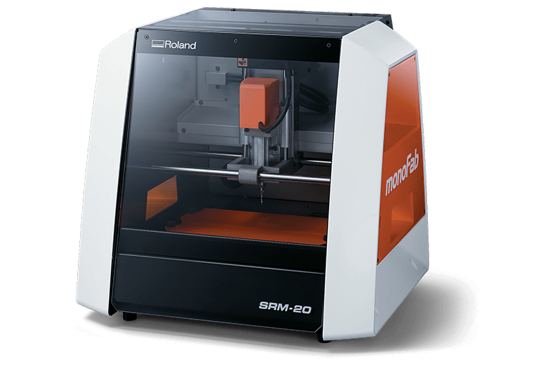
Roland SRM-20 vs. G-code CNC
At this point of the process, I had the following thought: is the Roland machine worth its price in front of the open source CNC? For a better explanation I think is a good point to compare both of them in terms of prices, performance and accessiblity.

| Item | Roland SRM-20 | G-Code CNC |
|---|---|---|
| Price | 4000$ or 3300€ | 181-242$ or 150-200€ |
| Axis | 3 (x,y,z) | 3 (x,y,z) |
| Working area | 232,2 * 156,6 * 61mm | 300 * 180 * 40mm |
| Software | Comercial (from G-code files) | Open source |
| Weight | 19.6kg | 4.5kg |
In my personal opinion, Roland machines are not worth it. I mean they are perfectly designed and may not generate as many issues as the open source one, but I think that's doesn' translate to 4000$. I won't be easy to have a major issue with the SRM-20, but what do you do if something happens? You should always get in touch with Roland and pray for a quick and cheap fix.
On the other hand, the open source CNC gives you the chance to fix, modify and explore its functions as much as you wish. It gives me the feeling that with enough time and trial-error I would end up having a better result than with the expensive one. Here are a couple resolution test, we did with both of them. We setted the same settings for both. I don't see a 3800$ worth performance to be honest.
I you want to forge your own opinion, or read about both of these amazing machines, here are the links to the Roland SRM-20.and here the one for the Open source table top CNC.
Climb vs. Conventional
Here is where things finally get technic. At this point, it is necessary to undestand the difference between working in climb or in conventional. The endmill of the CNC always spins clockwise, but the path of the G-code can be drawn clockwise or anticlockwise.
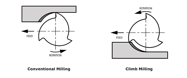
There are two distinct ways to cut materials when milling, conventional (up) milling and climb (down) milling. The difference between these two techniques is the relationship of the rotation of the cutter to the direction of feed. In conventional milling, the cutter rotates against the direction of the feed while during climb milling; the cutter rotates with the feed.
Conventional
- Chip width starts from zero and increases which causes more heat to diffuse into the workpiece and produces work hardening.
- Tool rubs more at the beginning of the cut causing faster tool wear and decreases tool life.
- Chips are carried upward by the tooth and fall in front of cutter creating a marred finish and re-cutting of chips.
- Upwards forces created in horizontal milling tend to lift the workpiece, more intricate and expansive work holdings are needed to lessen the lift created.
Climb
- Chip width starts from maximum and decreases so heat generated will more likely transfer to the chip
- Creates cleaner shear plane which causes the tool to rub less and increases tool life
- Chips are removed behind the cutter which reduces the chance of re-cutting
- Downwards forces in horizontal milling is created that helps hold the workpiece down, less complex work holdings are need when coupled with these forces
All credits for the technical explanation go to Harvey Tools for this simple yet intuitive pdf.
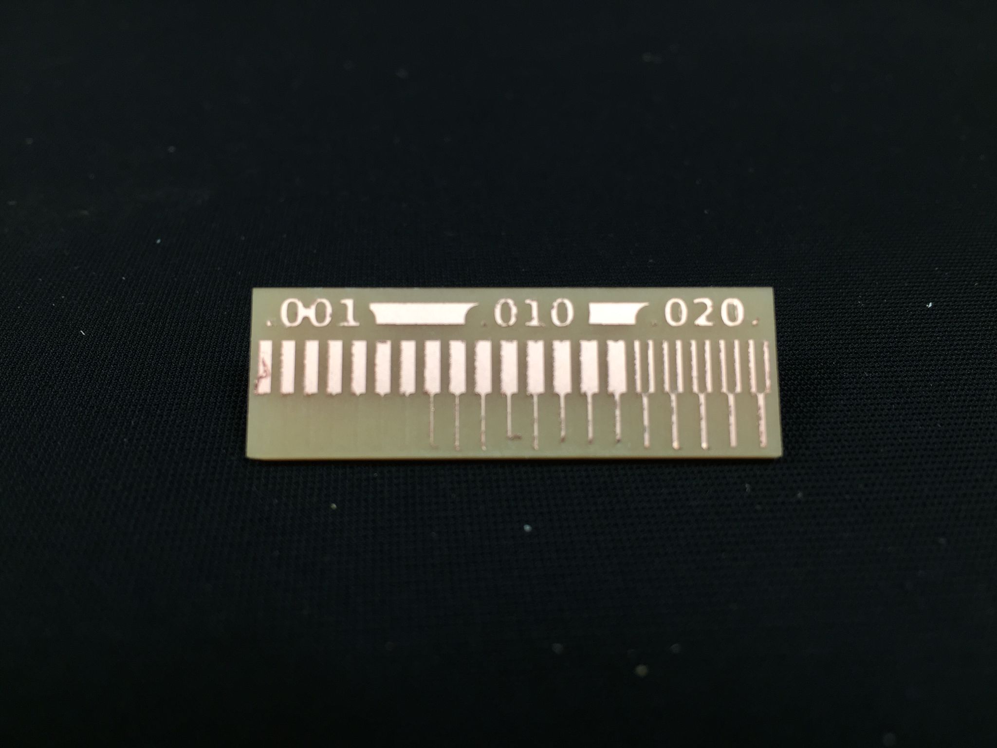
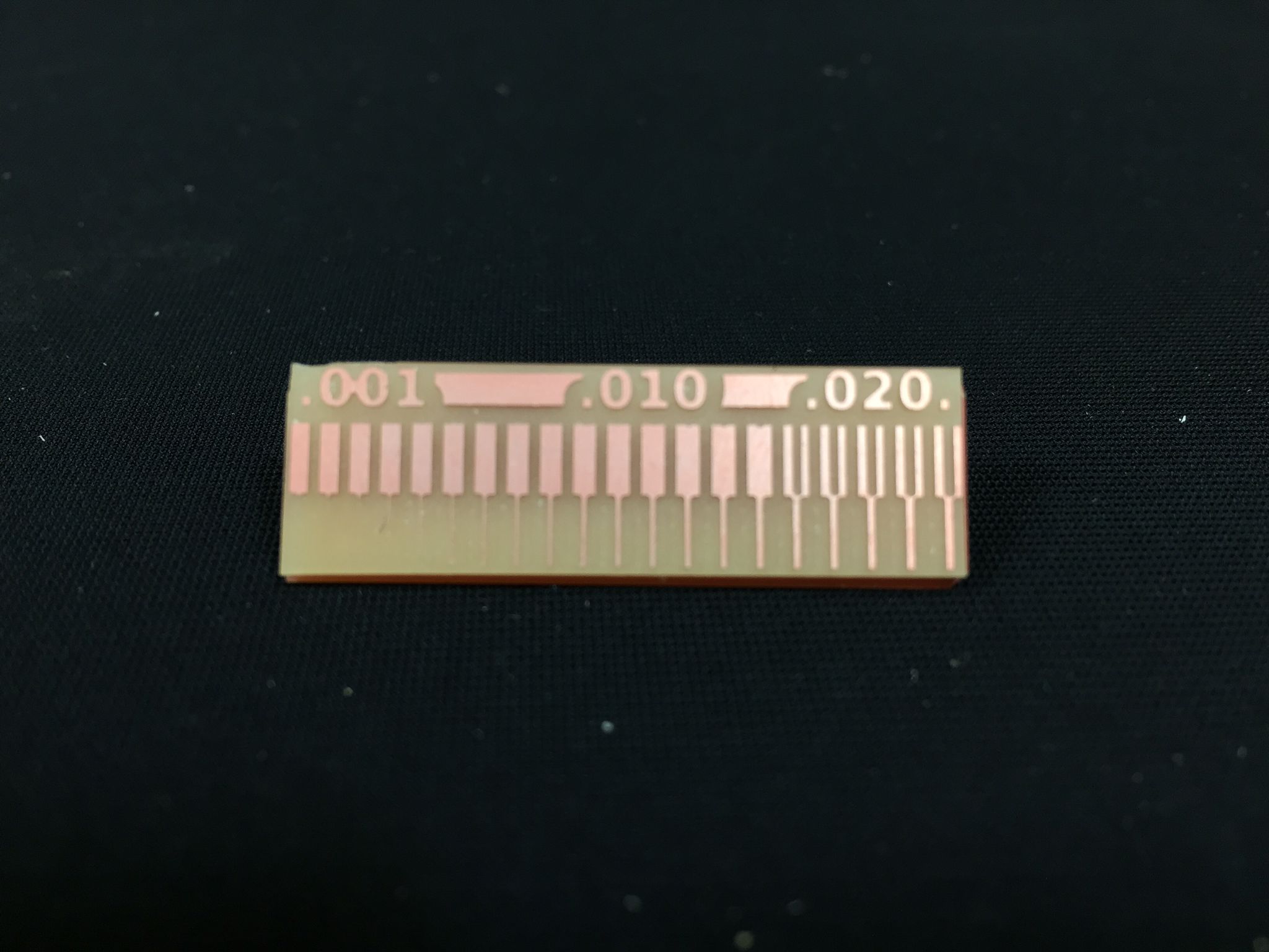
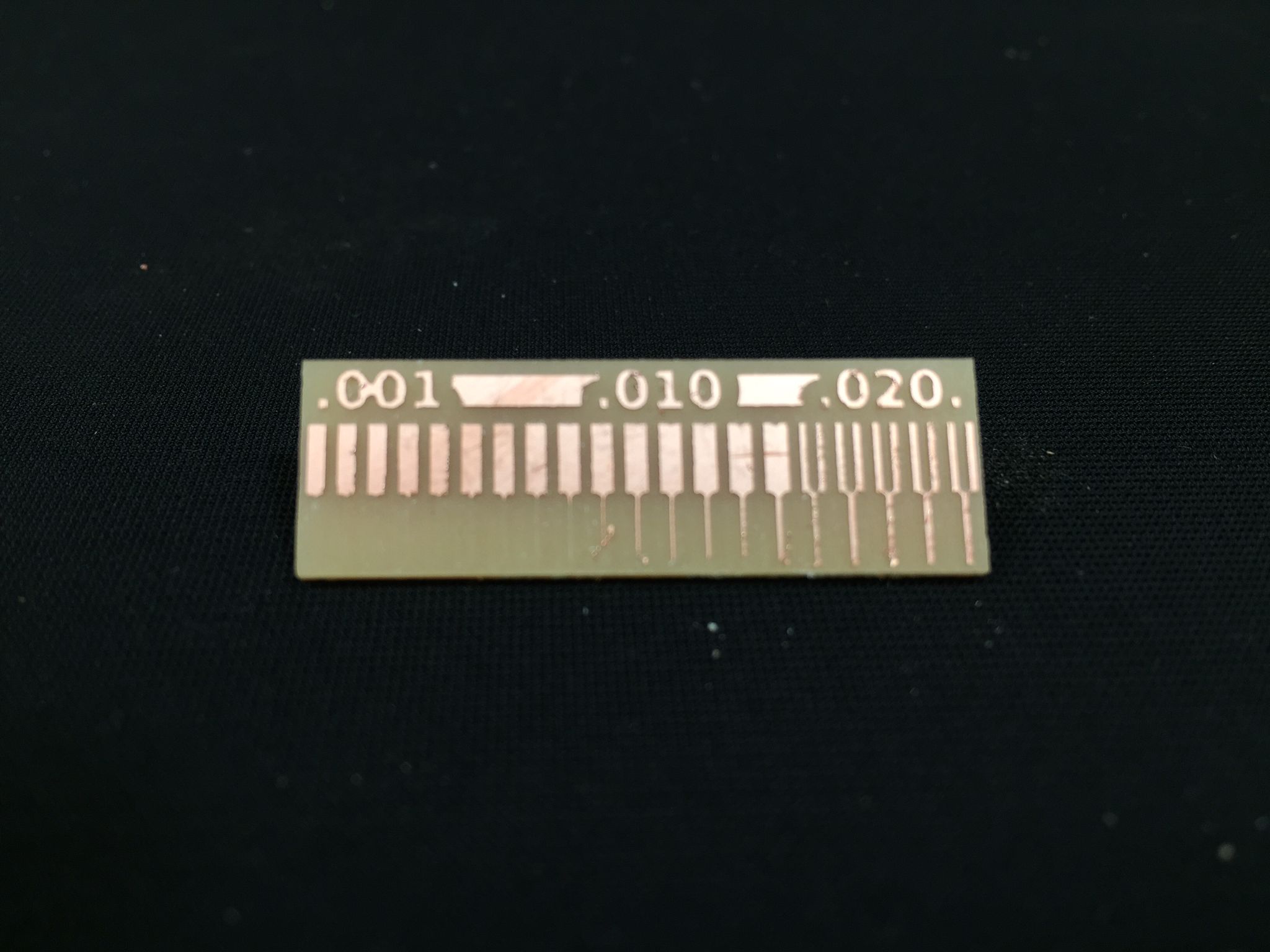
Tests
Following this lines, you can find the diferent results we obtained using the Roland mill. In first place you can find the resolution test for climb and next to it the conventional test. As you can see conventional results in a more definded shape, but with less control. On the other hand, climb makes a better approach for small parts, but less resolution on the bigger and more defined shapes.
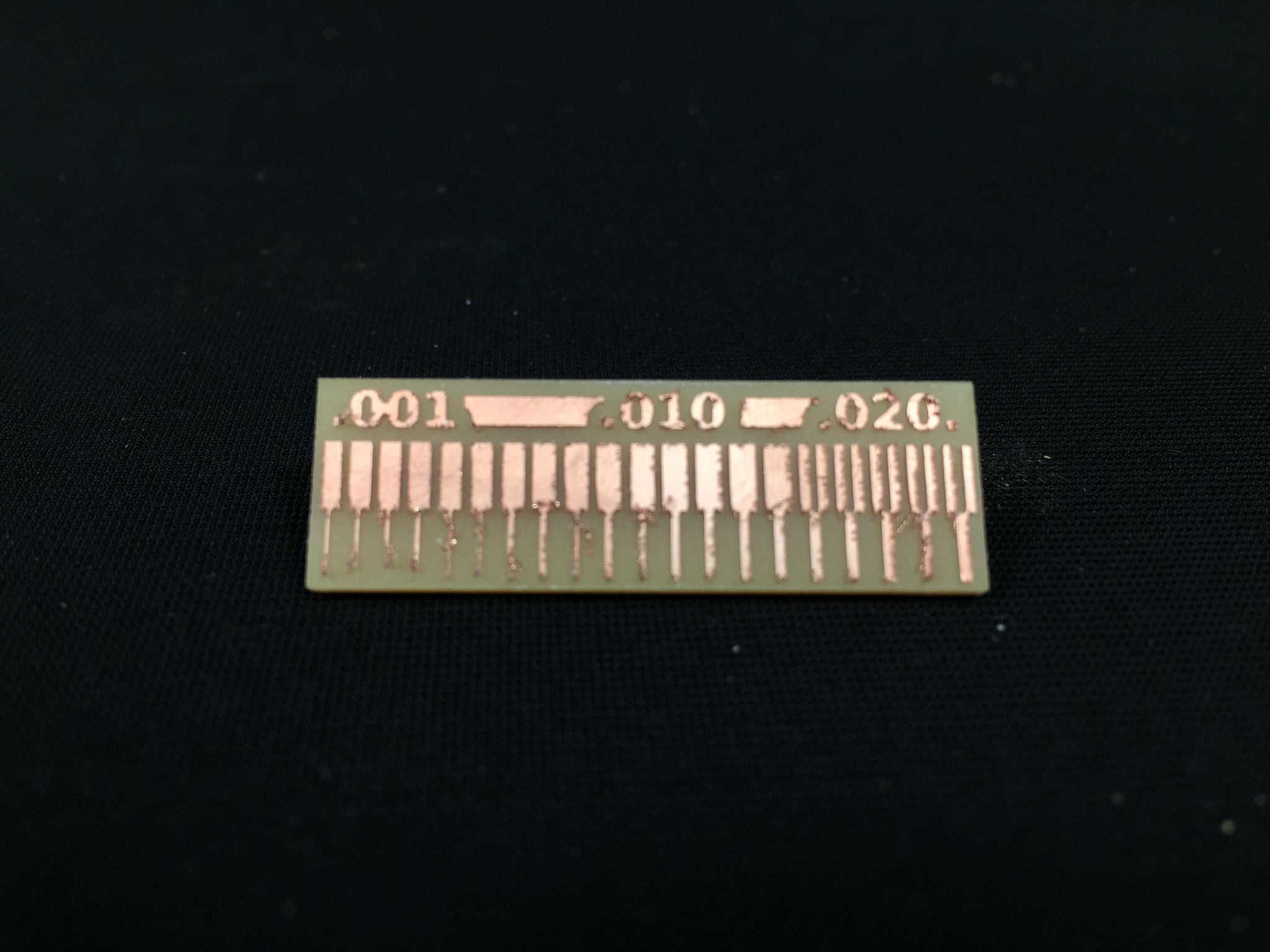
Now it is time to compare that same pair of settings but with the G-code open source machine. As you can see the result is the same as before: conventional defines more the shapes but with less control. On the counterpart, climb performs better at bigger shpaes than the small ones.
Step by step tutorial
I have talked about many things for the last minutes, so I believe it is a good idea to summarize all that information into a step by step tutorial. A the end of it, I excect you to have a good and more indeepth view of the settings and major points for milling your own PCBs.
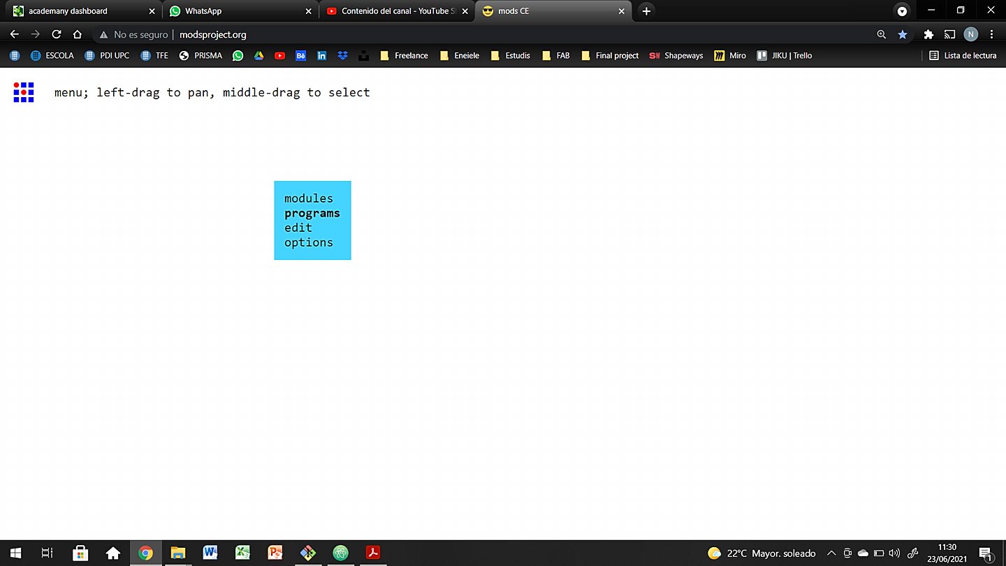
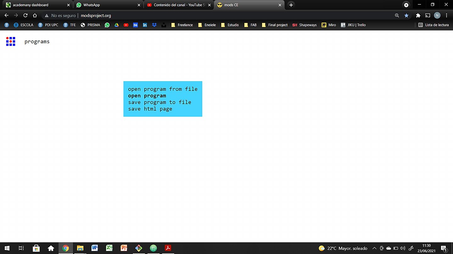
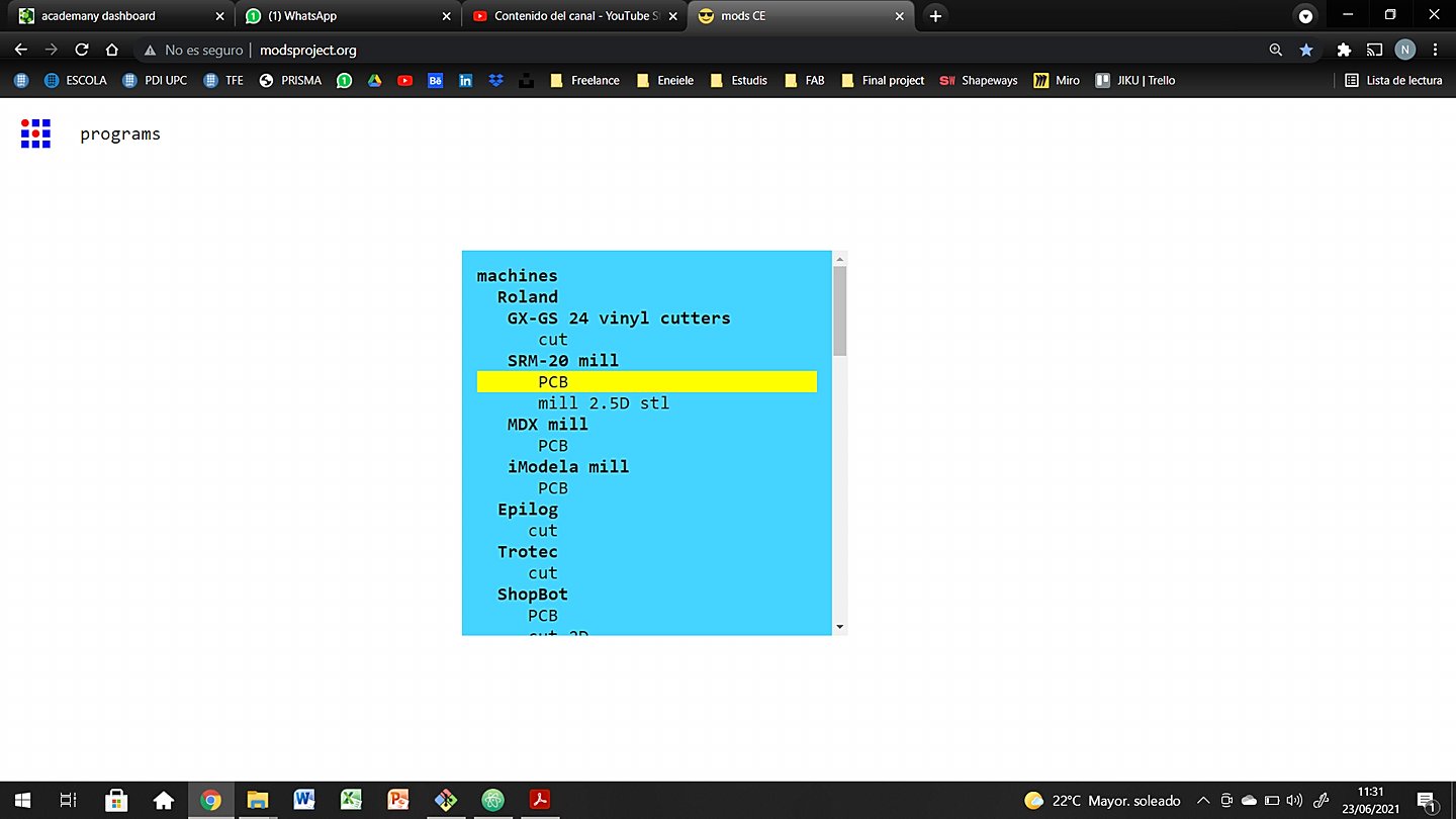
- Step 1: mods
-
Use the mods software to characterize your designs. You must upload your png file (1000dpi minimum), and choose the drill to use. Set the cut depth, speeds, origin if needed and climb or conventional milling. Calculate the file, check if it is corrects and download it.
- Step 2: export traces and interior
-
In or Fab Lab we have an embedded cloud where we upload our files, so we don’t have to carry USB sticks around. If not, simply connect your pen drive to the machine’s computer and upload it to the desktop or the folder you prefer.
- Step 3: load the drill (1/64")
-
Loosen the mill grips and insert the drill in place. These drills are delicate so it is better to keep the rubber cap on until it is fully loaded. If needed, move your Z axis to a point where you can work easily. Use an Allen wrench to loosen and tighten the drill firmly. Try to insert the drill as deep as possible to avoid vibrations during the mill process.
- Step 4: stick the copper plate
-
With double sided tape, stick carefully the copper plate where needed. Use as many tape as needed and avoid letting it twit under the Plate. This will end up being a higher point when milling.
- Step 5: set XY origin
-
Use the motor controls to move the mill in the X and Y axis. Once it is barely in place, it is recommended to lower the Z axis closer to the working plate. This will give you a more accurate aiming. Set the origin.
- Step 6: set Z origin
-
Making sure that you are in the XY origin, start the drill motor and slowly get closer to the copper plate. On you see little chips coming out of it, try to lower it approximately a 0.10mm for extra definition.
- Step 7: upload traces file
-
Now it is time to upload the file to your computer and get ready to mill.
- Step 8: air mill test (optional)
-
If you are not sure of the future performance of your files and settings it is a good idea to set your Z origin at 5 mm over the copper plate. Then start milling without touching, so you can check the speed and overall performance of your files.
- Step 9: mill the traces
-
Start the milling. Simply wait for it to stop, but always keep an eye on it just in case something fails during the process.
- Step 10: swap the drill (1/32")
-
The 1/64” drill may be hot so watch out when manipulating it. Put the rubber tip on and loosen the grips. Do the opposite process for the 1/32 drill. Check step 3 again if needed.
- Step 11: set Z origin
-
Making sure that you are in the XY origin, Repeat the process in step 6 but this time with the thicker drill.
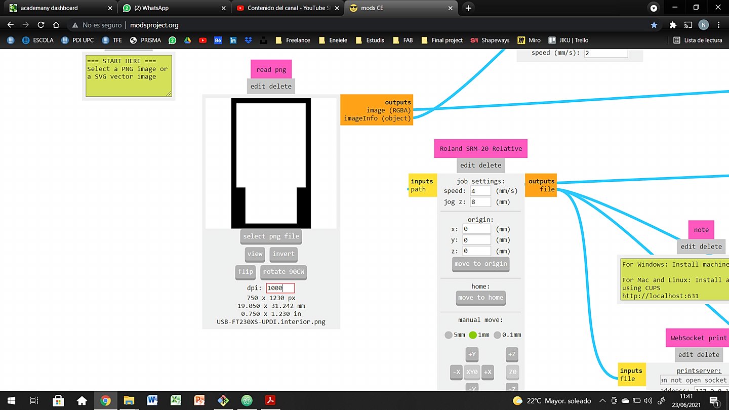
- Step 12: upload interior file
-
As you did with the traces file, upload it and ge tready to mill.
- Step 13: mill the circuit
-
Let the machine do its work, but always keep an eye on it for extra safety. If something doesn't go as planned quickly stop the process.
- Step 14: cleaning
-
Unstick the PCB from the working plate, making sure that you don’t scratch the milled surface. Use the softest brush possible to clean all the chips. With a pair of tweezers, clean all the edges carefully. Finally use a cotton swab soaked in alcohol to clean the surface. Be gentle because some of the copper circuits might be tiny.
- Step 15: soldering
-
Prepare your soldering equiment and electronic components, to be soldered. Solder them all in place.
Individual Assignment
I think that this week it is better not to go crazy. Instead I believe it is a better approach to go for a basic project, but on the meanwhile, understand as clear as possible all the process involved.
Doing this chapter you will see my way trough my weekly assignment, with the ups and downs of it. It has been tough, but enriching at the same time.
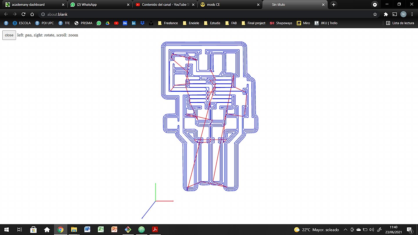
Generate G-code files
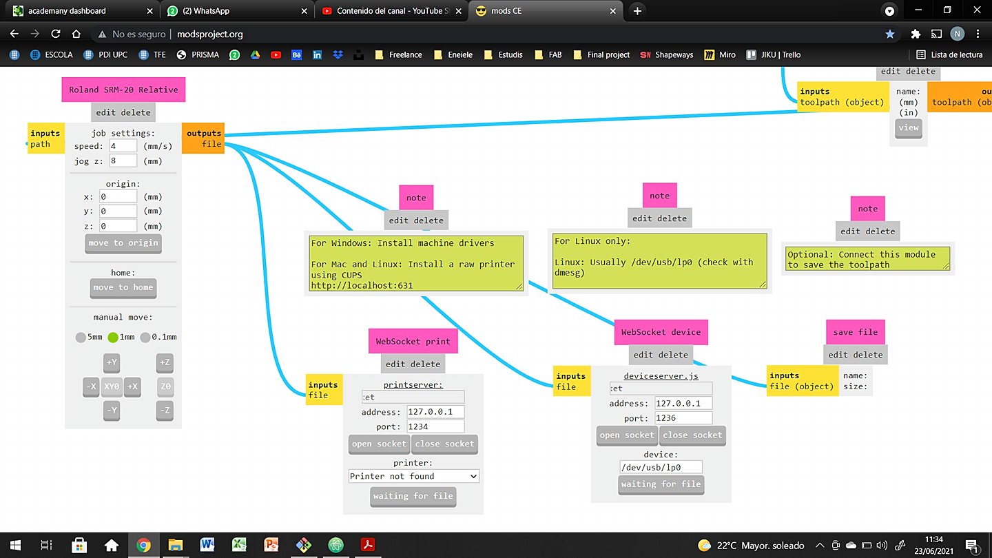
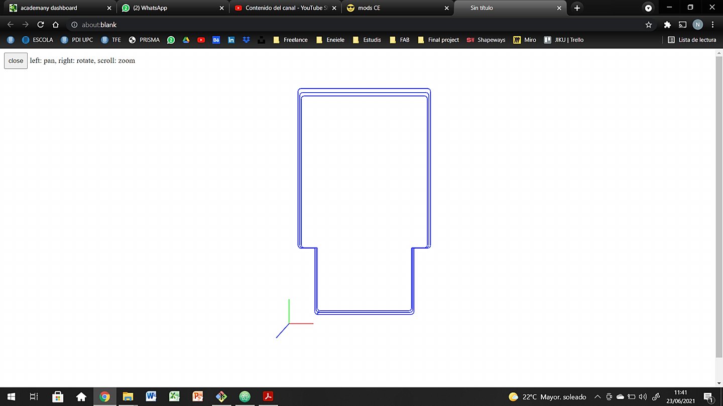
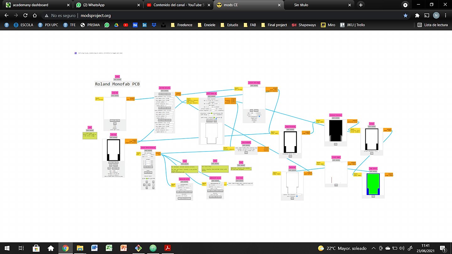
First thing to do was set my ModsProject programs and uppload them to the cloud. Recover them from the machine's computer and set all the parameters like in the step by step tutorial above.
For me to remember later or maybe someone who ends up reading this lines, here you have a series of images to remember the process and the values I used.
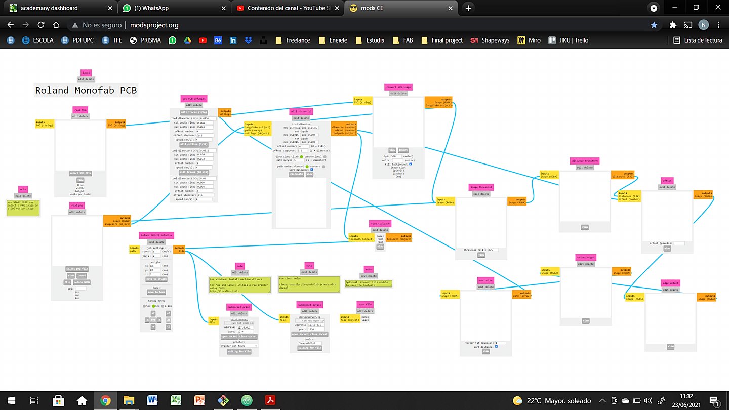
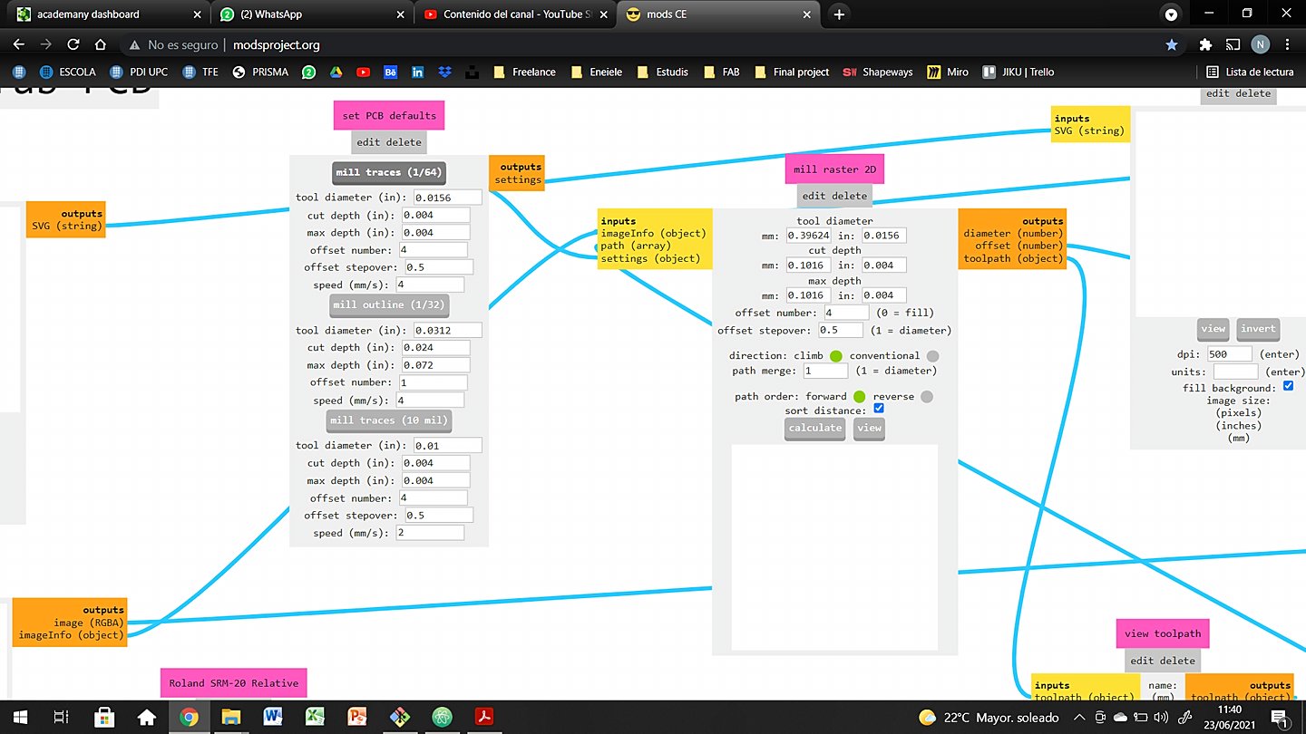
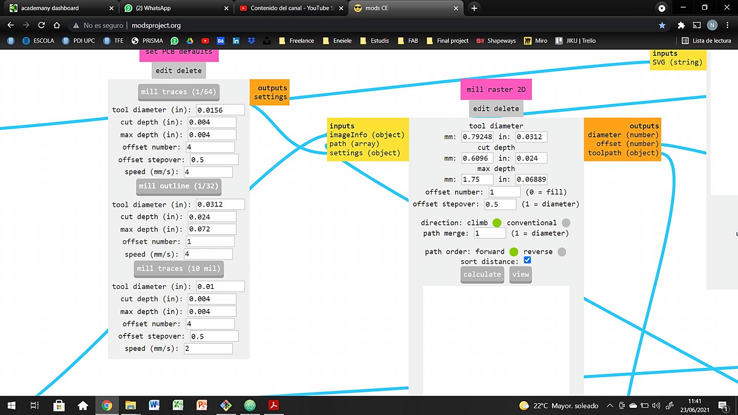
The process and the settings in MODS are the same for UPDI and FTDI.
Milling process
With all the tests we did with my collegues at the Lab, this part was not supposed to be that hard. But trust me, it ended up being the hardest one. I milled the UPDI without any inconvinient, but the FTDI was another story.
UTDI went perfectly fine at first try, so let's focues on the FTDI, the tricky one.
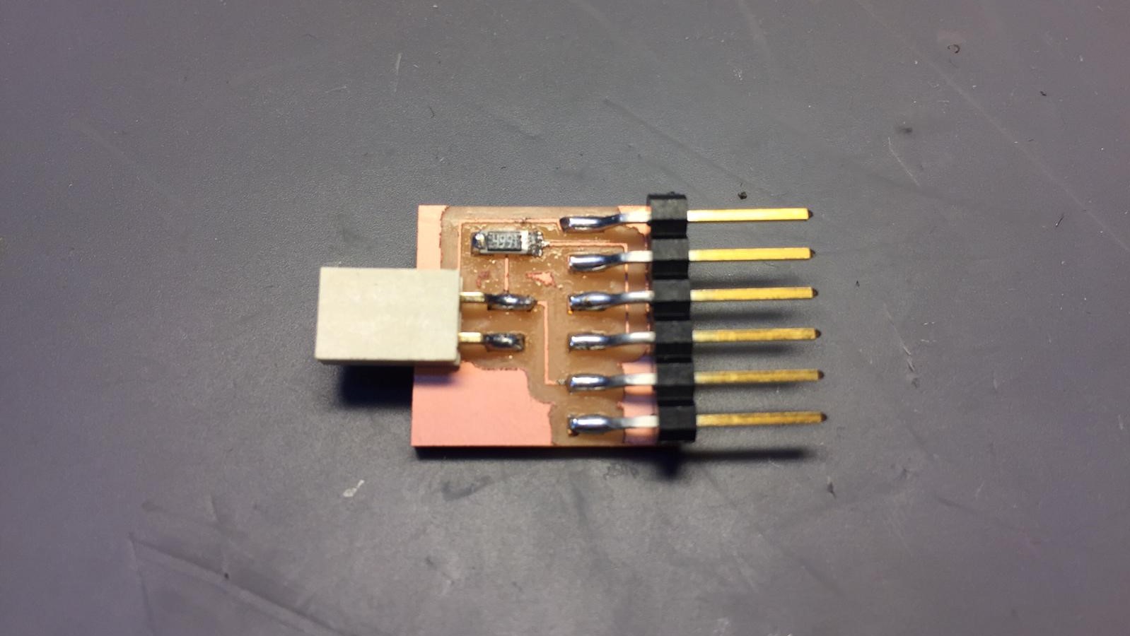
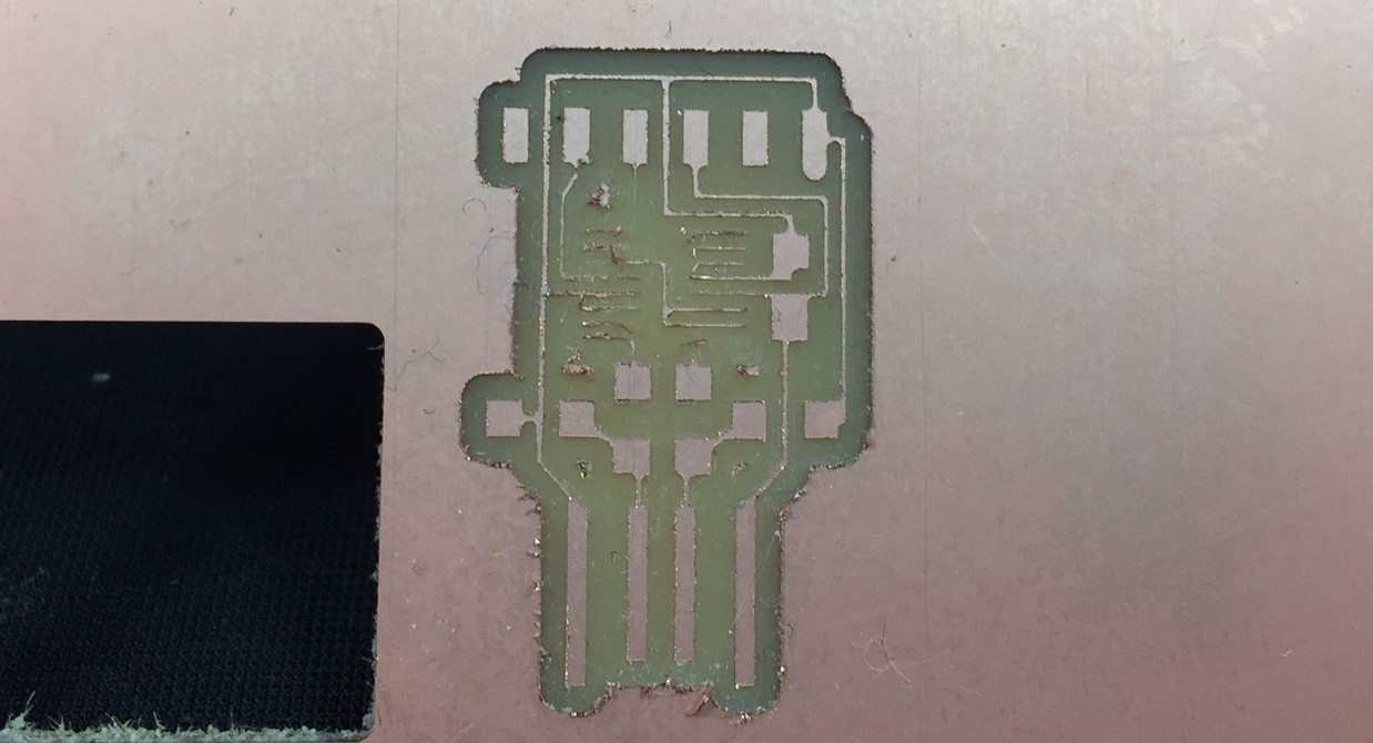
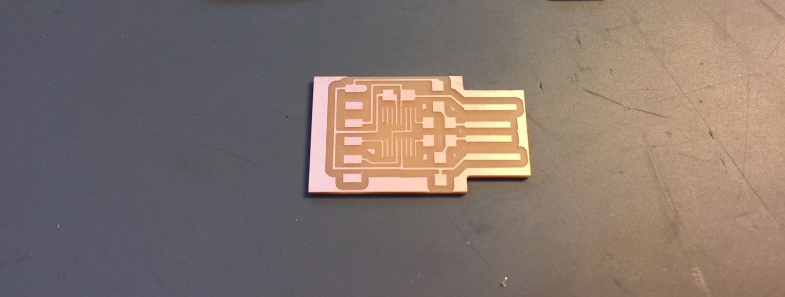
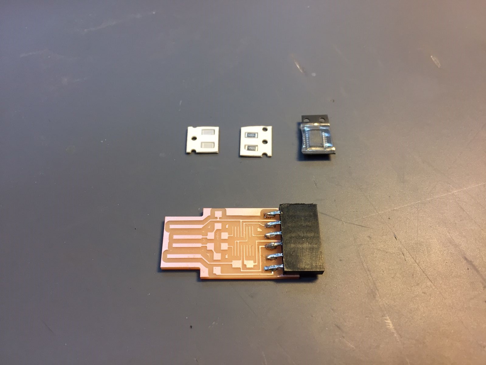
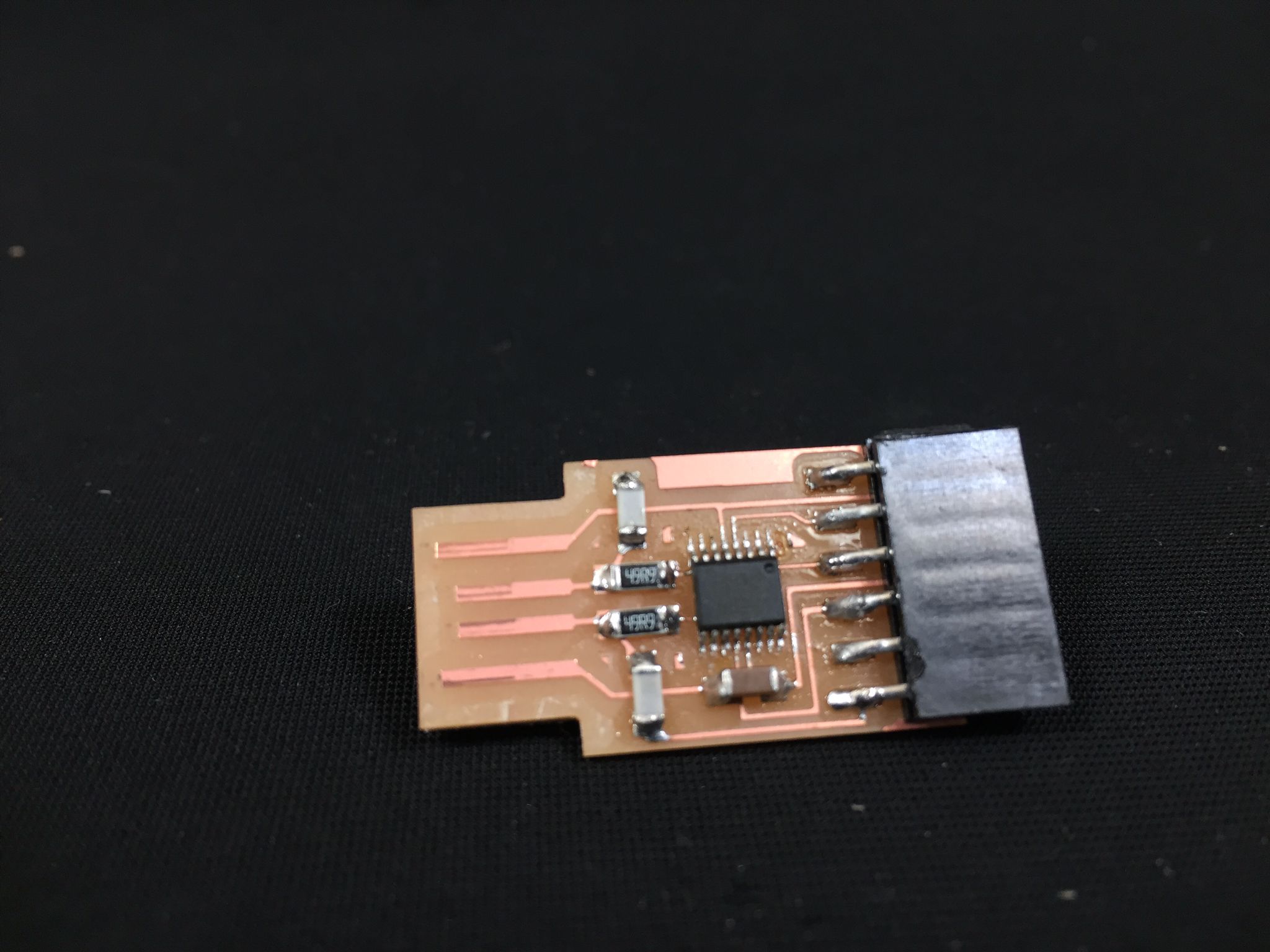
Iteration 1: microchip tracks were too thin
When the FTDI cut was finished, I discovered while cleaning the plate, that the copper rails were too thin. I did not understand why, since another colleague working with the same file had achieved a great result. The only difference between the two was the machine. That made me think that something was wrong with the hardware.
The fact that the rails were too thin made it impossible for me to weld correctly. Also taking into account that the legs of the microchip are very small and close to each other.
So that you better understand what I mean, you have an image below. Look at the center lanes, the ones that are thinner than the others.
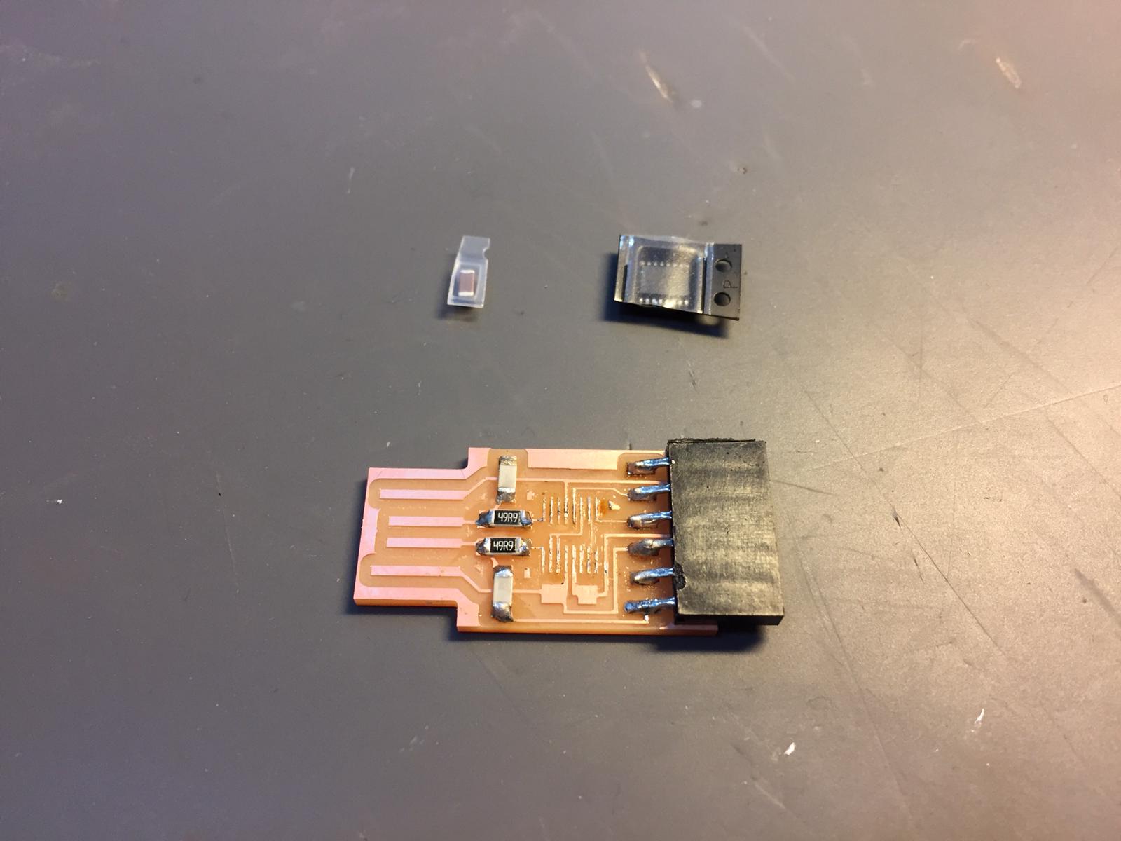
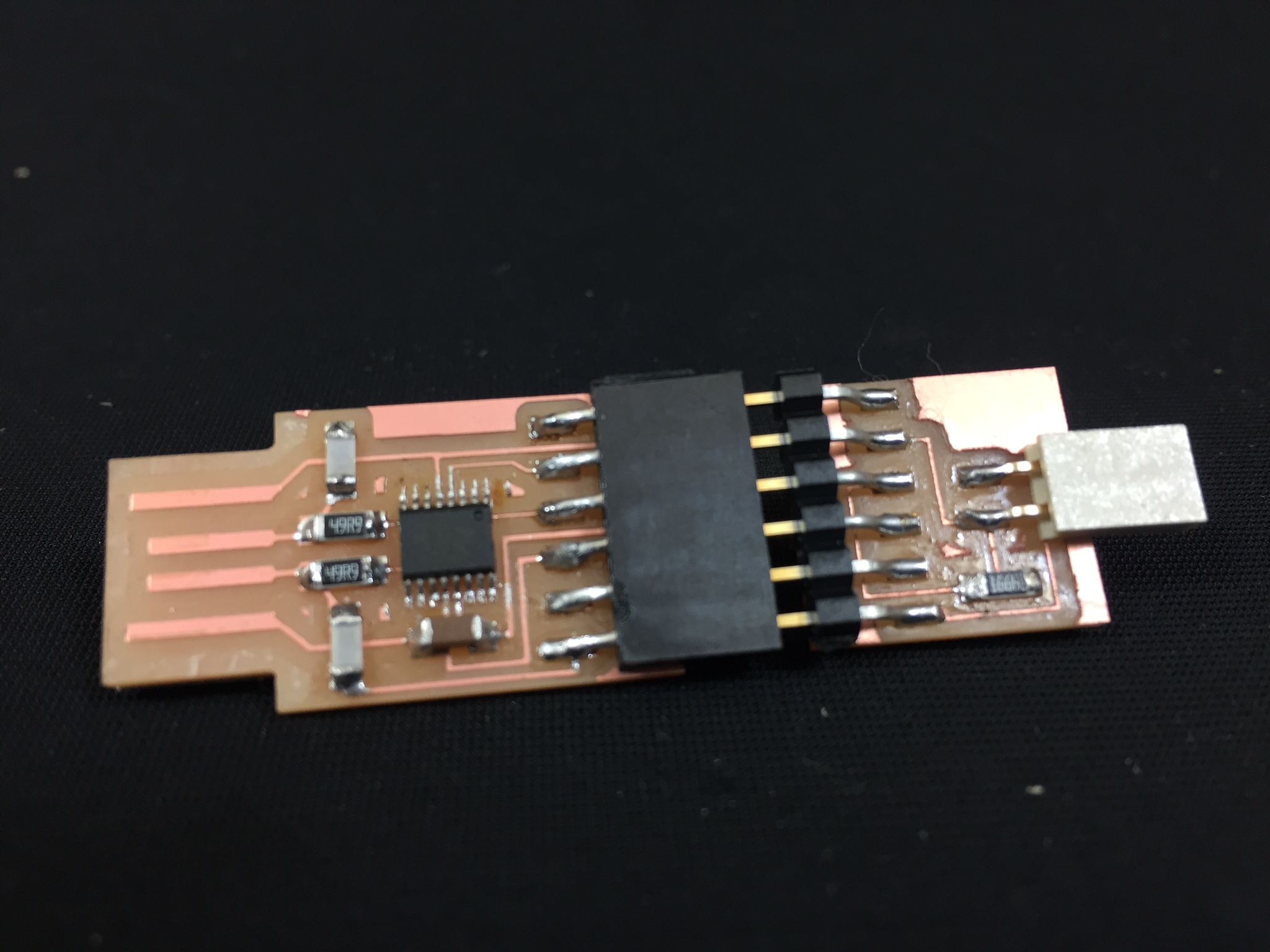
Iteration 2: finally ok
After some small calibrations I decided to switch to the other Roland. I was not being able to find the mistake in my files, neither in the machine settings. I repeated the whole process on the other SMR-20 and it turned out to be a great PCB. The tracks were super defined and hardly stuck to the plate. Finally I able to start soldering, after 2-3 hours of test and error.
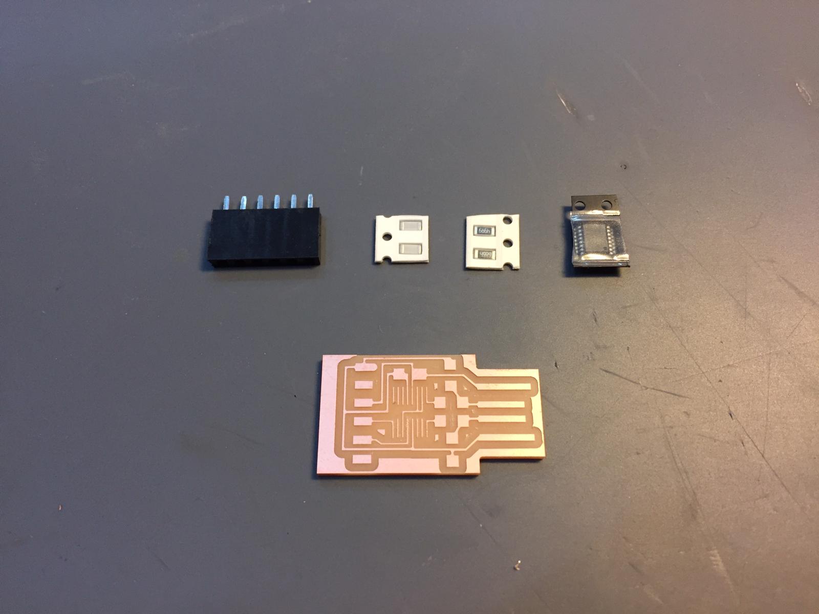
Soldering
This process was the most pleasing for me. I had already soldered before but in a much bigger scale. When I saw the microchip legs size, the almost invisible resistors and capacitors I was absolutely terrified.
Although, I had so much fun during the soldering stage. I felt it was a relaxing and evading task. Some chill music and I might to able to spend hours soldering PCBs.
UTDI
Everything went well with the UTDI. The components were not that small and the soldering pads were big enough to work comfortably.
FTDI
This one was a lot more tricky. The microchip especifically. That component is such a pain, due to its size. 16 legs to solder spaced between them for less than half a milimeter. The process I uses was to solder all them together, place it in the PCB and the extract the excess with the copper braid. Worked perfectly at the second trial.
Once everything was soldered it was time to test if the FTDI was working fine.
Testing
Before testing I scratch some copper that seemed to be about to cause a short. Also I added with some doublesided tape, a piece of plastic for a better fit in the USB port. Once everything was in place it was time for the actual test. I plugged the FTDI in the USB port and nothing happened. I was almost crying of the frustration.
What went wrong?
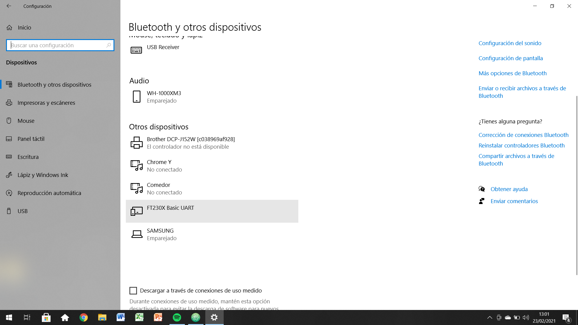
After some minutes, Adrien told me that he had a similar problem. His FTDI was not being recognized by the PC because of one leg that was not properly soldered. We though that might be the issue with mine too. Checking the microchip with the multimeter everything seamed to be ok, except for the alimentation pin that was no giving any current back.
After some more testing I realizes that if I pressed the pin a bit against the PCB the connection worked. Basically the solder was stuck to the microchip but no to the copper track.
After a bit more soldering and cleaning I repeated the PC test an everything was fine!
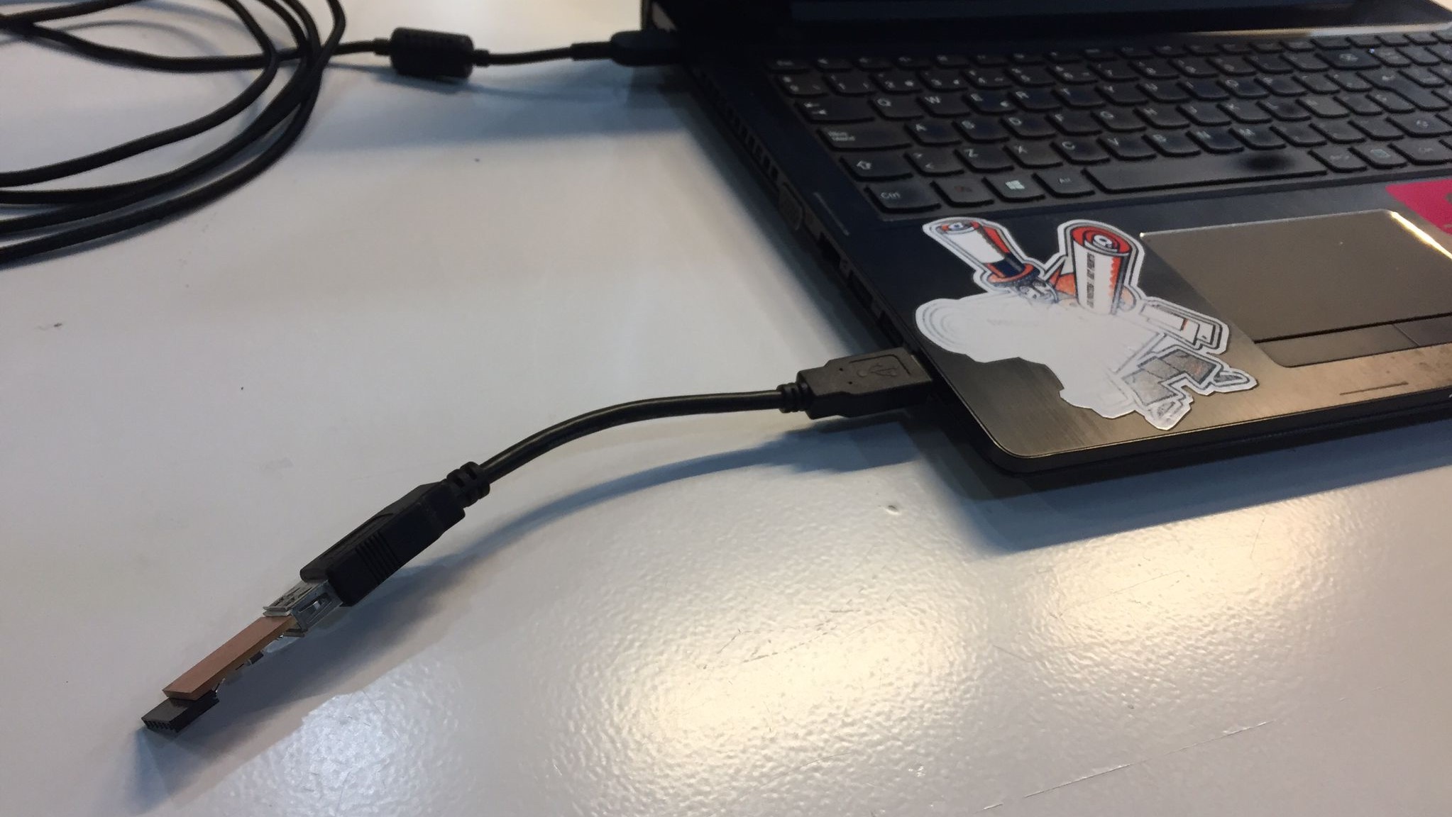
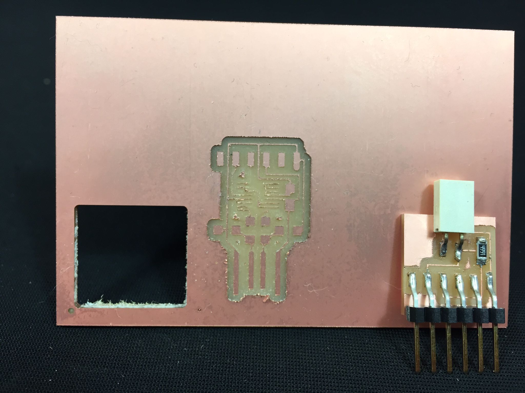
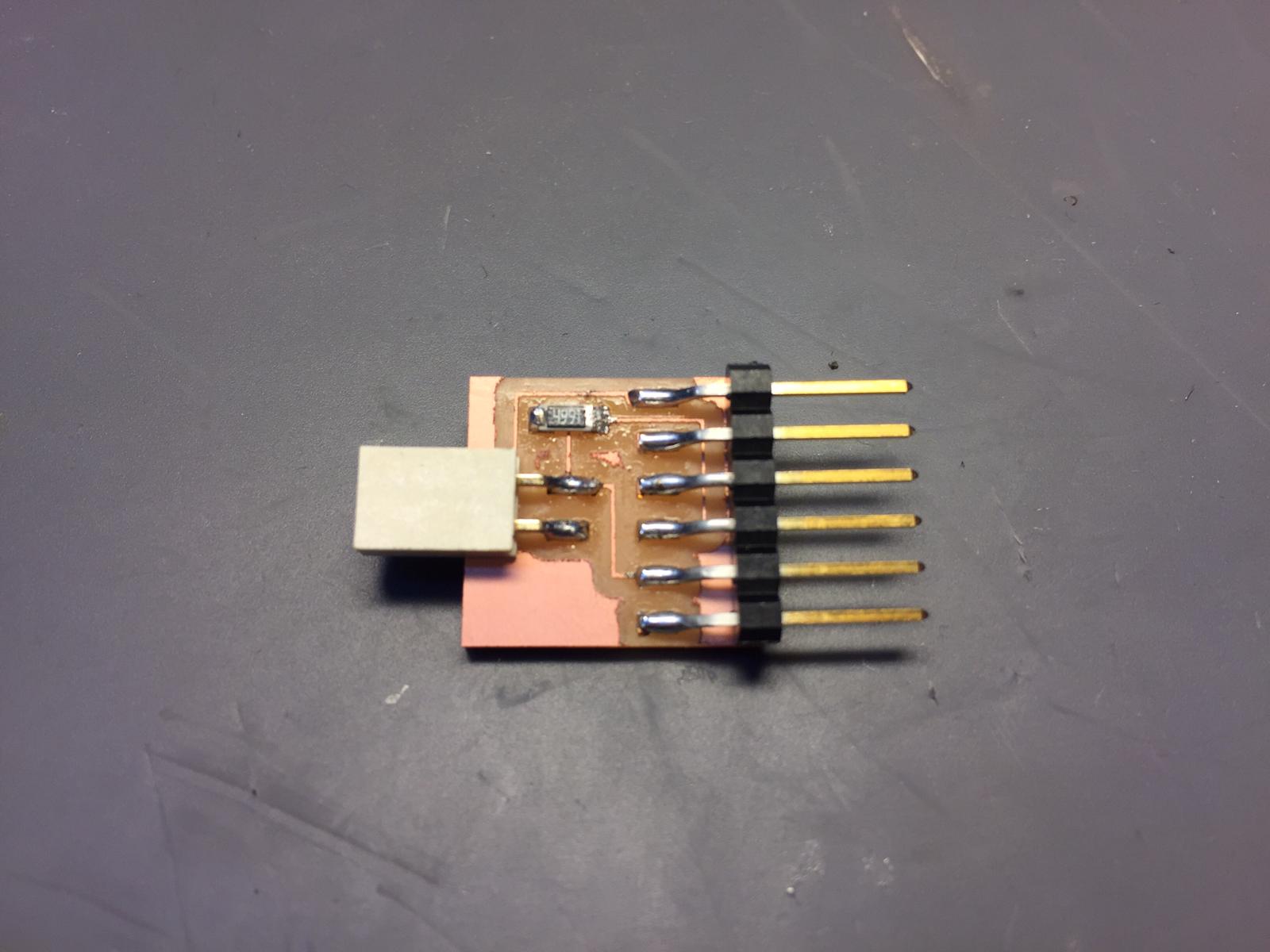
Hero Shots
I think these following images make me happy at a whole other level. Finally being able to see my first electronics made by me is incredible. Here are some pics from the final result I achived this week.

Settings for Mods
Although it is likely that as the course progresses I will learn better how to calibrate the Mods settings, for now I would like to make a small summary of which are the most viable:
Traces Mill 1/64"
- Speed: 4mm/s
- Jog: 8mm
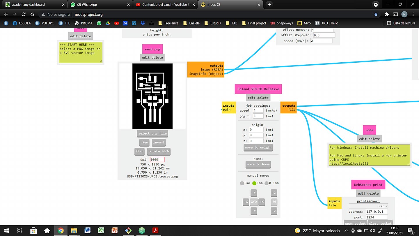
- PNG size: 1000dpi
- Tool Diameter: 0.39624mm
- Cut Depth: 0.1016mm
- Max Depth: 0.1016mm
- Offset Number: 4
- Offset Stepover: 0.5
- Path Merge: 1
- Direction: climb
- Path order: forward
Interior Mill 1/32"
- Speed: 1.5mm/s
- Jog: 8mm
- PNG size: 1000dpi
- Tool Diameter: 0.79248mm
- Cut Depth: 0.6096mm
- Max Depth: 1.75mm
- Offset Number: 1
- Offset Stepover: 0.5
- Path Merge: 1
- Direction: climb
- Path order: forward
Conclusions
This is the first time I think it is mandatory to make a little list to summarize the massive amount of information and knowledge, we have generated for the last 7 days.
- Conventional and climb are so different, taht it is not possible to give a full answer. Each of them have their own characteristics and may be useful depending on the activity, machine, workspace... For PCB milling I would work with climb.
- Electronics milling is a complex activity and can go wrong really quickly. Eventhough, it is exciting, useful and allows the user to imagin and create their own electronic circuits.
- Being able to develope from scratch your circuits is something I didn't know was inside the FabLab philosophy. Nevertheless I believe is an unbelivable tool that should be better known. Sometimes we only think about 3D printing and laser cutting.
Original Files
Link to Original files from this week.
What to improve for next assignments?
I loved this week, because I always wanted to try CNC machines. It has been espacially cool because I finally undestood the PCB fabrication process. I always been kinda scared of electronics and always wanted to try CNC, so... PERFECT WEEK. It has also been sweet because all the teamwork and the amount of trial-error process that we went through.
This week 5 I am going back to work almost full time, so it is gonna be more stressful than it has been until the moment. There are a couple things I need to keep an eye on:
What to keep an eye on during week 5?
· Time management is going to be crucial, to be able to achieve all the assignments. I must start documenting during the weekend and plan the week in advance.
· Use the commuting hours to develop the project management phases and plan my week.