Week 15:
Interface and Application programming
This week the work will revolve around my final project, but I am not sure that the results can finally be used for the project. I find it interesting to make an interface to it but more for the pleasure of learning than for the need to add it to my project.
I think the interface is a great way to bring data closer to users. Many times the complexity of data collection makes this part of the technique take a back seat. That comes from the difficulty in understanding some concepts and the usual brutally simple and unattractive data interfaces.
The data is in the end, the product of a lot of work. Being able to bring that work in a simple and beautiful way to other people is a very powerful tool. Many of the authors that I like, such as .Domestic Data Streamers, use aesthetics to bring their great data work closer to their visitors.
The assignments for this week are:
Group assignment:
• Compare as many tool options as possible
Individual assignment:
• Write an application that interfaces a user with an input and/or output device that you made
Group assignment
Most of my colleagues this week have used different software to interface our sensors and outputs. I think a good way to compare the information and see what features each software has is to review its assignments for this week. In addition I also have in this way a knowledge base to consult in the future.
Conclusions
As I was telling you this week, we have all gone down different paths when it comes to making the interface. That is why I consider it interesting to make a section of conclusions in which to explain the pros and cons of the different alternatives to interface.
The conclusions were drawn during the local interface class that Xavi gave us. In that class we saw many examples of software, each with its particularities.
Grasshopper-firefly
Using Firefly module in GrassHopper we saw how to interface an Arduino with our webcam. The communication flow is a bit like with Arduino when working with serial :
- Make sure that the Serial is available
- Make sure that code and interface are running at the same baud rate
In the example we used, we played with the color content of the webcam video stream make an average of color content to create points and then once we have the point we could play with them.
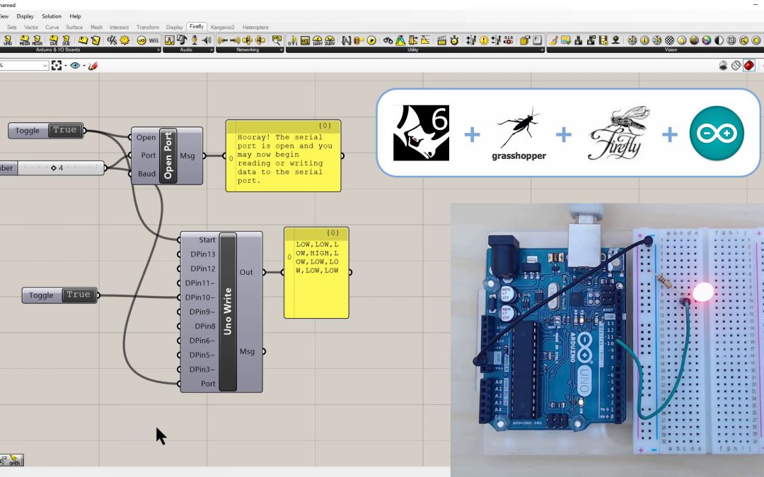
This software has enormous power, but in my eyes it is excessively complex. Using grasshopper as a root to work on, everything is too confusing and heavy for me. In addition, you also depend on Rhino, which is not easy to achieve without student licenses or similar. A lot of power, difficult interaction and access.
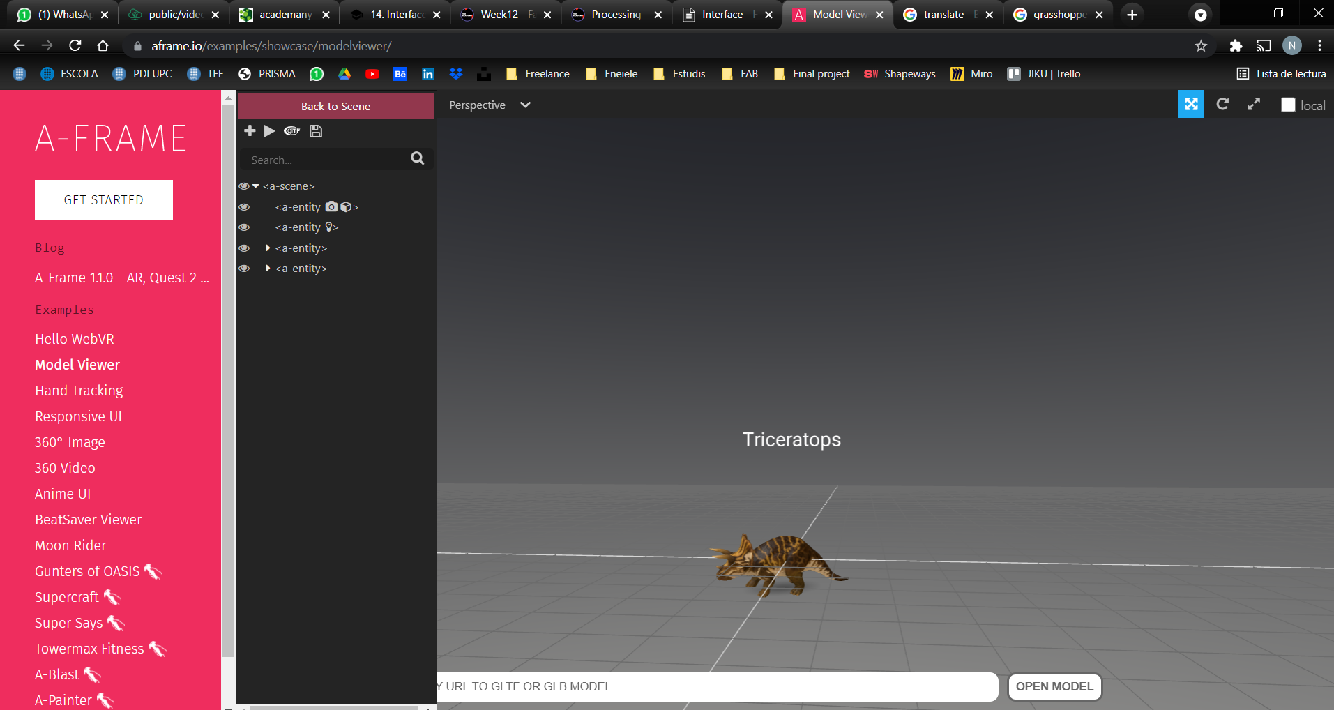
Aframe
Although I see it very optimized for VR, I also think it is a great tool for making visual samples of renders or CAD models that need an interface. It occurred to me that it would be great to see inside products or buildings. Super powerful, too focused on VR. Difficulty related to inputs
Processing
This other program is perfect to work alongside the Arduino IDE. It literally uses that application's serial monitor to receive the data.
It is probably the easiest for a beginner, but it quickly falls short when it comes to the graphical power of the program. As I was saying, it is very designed for Arduino that does not move large amounts of data. Very simple and intuitive, relatively weak and with few resources. Learning curve too short
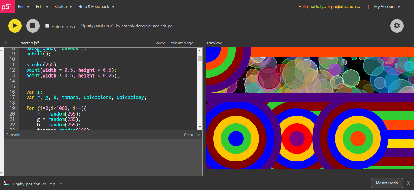
P5
P5 is the online version of processing to try to summarize it in a few words. It works through the browser (which can be good and bad at the same time).
The conclusion is the same as with Processing: simple and intuitive for beginners, but it presents little experience in the graphic possibilities it offers
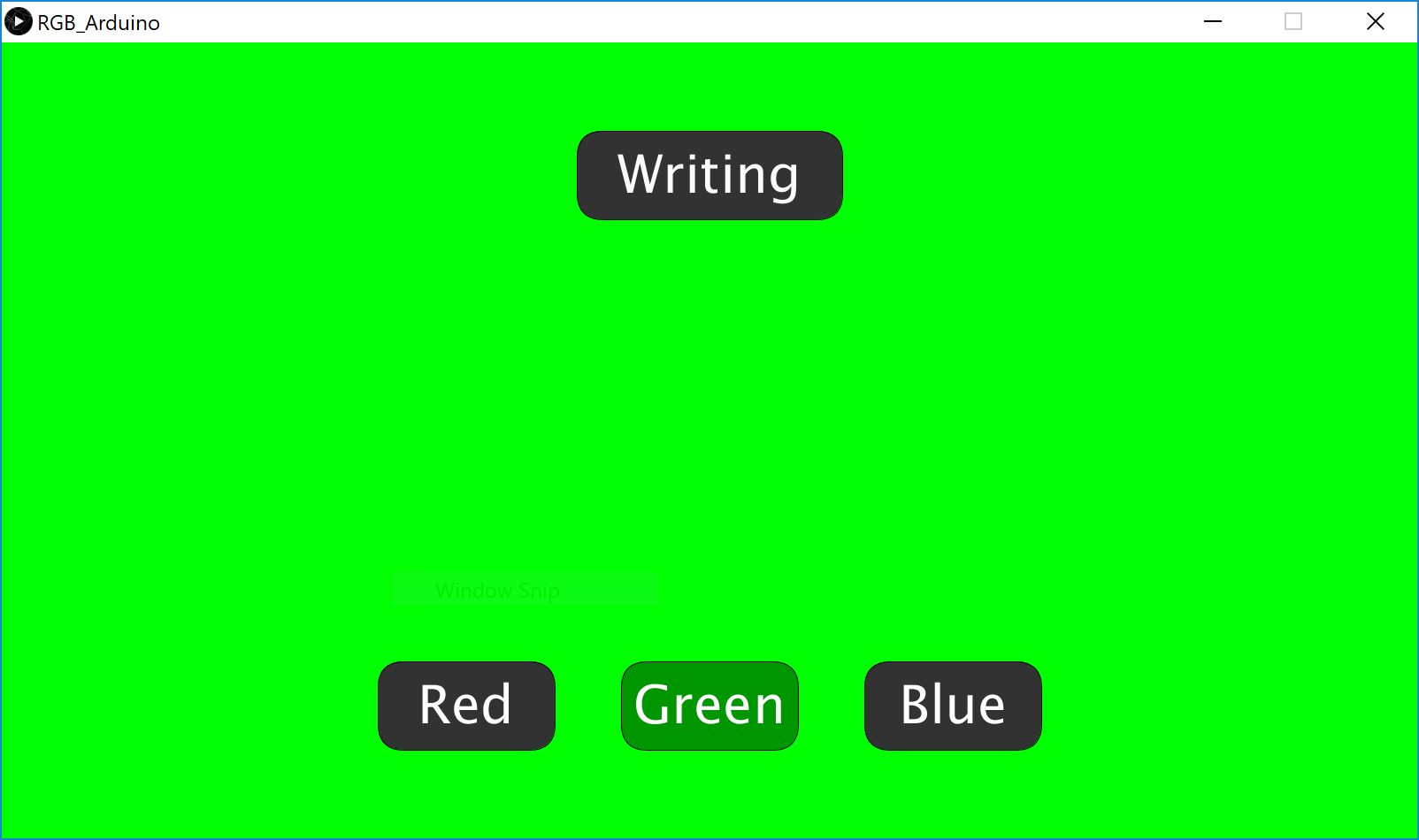
AppInventor
This was created by MIT to bring the interface and processing to the most beginners: children and newcomers to programming. It is very simple because of the way you work, but looking for visual finishes is almost impossible. It is a simple program to relate electronics with a simple visual interface.
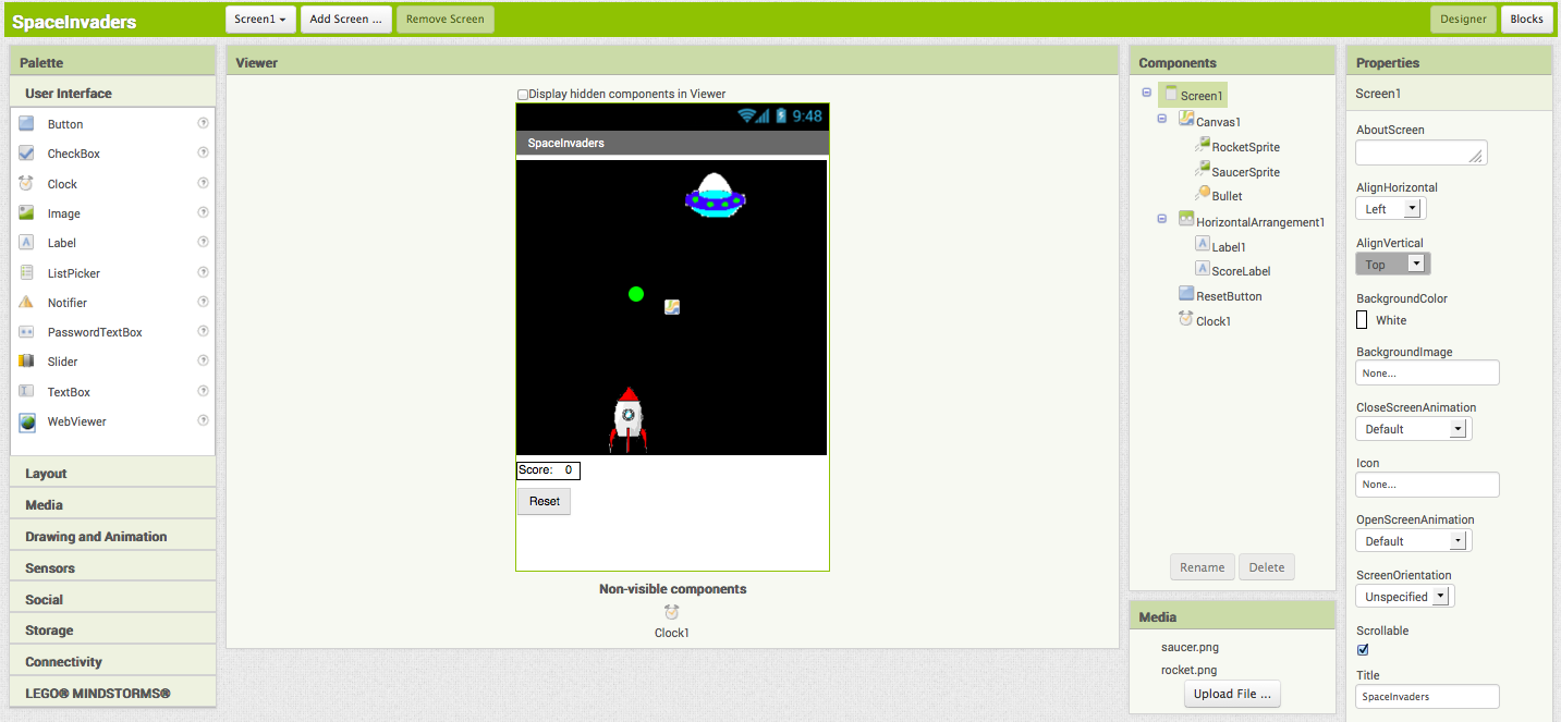
As a general conclusion of the program, I would say that it is the best for new legacies who want to make mobile apps with simplicity and speed. great workflow, simple and intuitive; very thought for apps and the graphics are difficult to take to the next level.
Individual assignment
To start the week I would like to show you the interface for my VEML6040 color sensor. As I mentioned above last week, the idea is to be able to visualize the data obtained by the sensor, but in a more pleasant way.
Processing for color sensor
The color sensor I am working with is prepared to return the following values:
- RED
- GREEN
- BLUE
- CCT (Correlated Color Temperature)
- AL (Ambient Light)
Reading the data through numerical values, I find it somewhat uncomfortable although they give a good feeling of how the value changes. Investigating a bit I found that with processign it was possible to make real-time graphs of the data that the sensor received.
I don't know much about the Processing program but thanks again to Adrian I managed to graph the data from the VEML6040. The graphing data jumps directly to processing through the serial data monitor (RX / TX). The following code converts the data received through the serial port to a R, G, B, AL bar graph.
Connections
The connections are simple, connect the SCL and SDA pins between them (the breakout already has the pullup resistors and the capacitor to favor data exchange. Finally, connect GND and VCC between the MINUSUNO and the breakout board.
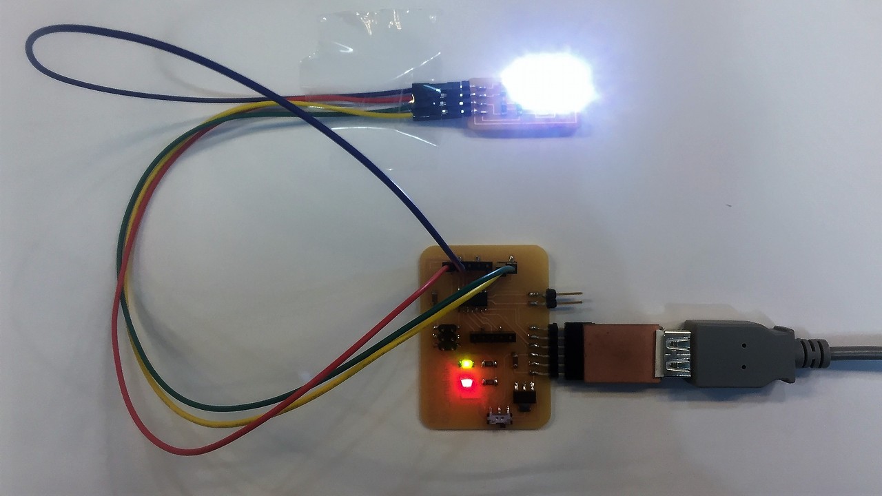
To communicate the information with the computer we use the RX / TX ports through the FTDI to USB connection. That is the way the Arduino IDE can read the data on the serial monitor. Then to bring the data to Processing, the same software communicates with the USB port that is using the board and Arduino IDE.
Arduino IDE
In Arduino IDE we work the code so that the microprocessor is flashed with the specific program. Here is the commented code that I am using for now. I want to take this week to fully understand what it does and try to improve it if possible.
//Fab Academy 2021 - Fab Lab León
//Color
//Adrianino (edited by _eneiele)
//ATtiny1614

/*

The MIT License (MIT)

Copyright (c) 2015 thewknd

Permission is hereby granted, free of charge, to any person obtaining a copy
of this software and associated documentation files (the "Software"), to deal
in the Software without restriction, including without limitation the rights
to use, copy, modify, merge, publish, distribute, sublicense, and/or sell
copies of the Software, and to permit persons to whom the Software is
furnished to do so, subject to the following conditions:

The above copyright notice and this permission notice shall be included in all
copies or substantial portions of the Software.

THE SOFTWARE IS PROVIDED "AS IS", WITHOUT WARRANTY OF ANY KIND, EXPRESS OR
IMPLIED, INCLUDING BUT NOT LIMITED TO THE WARRANTIES OF MERCHANTABILITY,
FITNESS FOR A PARTICULAR PURPOSE AND NONINFRINGEMENT. IN NO EVENT SHALL THE
AUTHORS OR COPYRIGHT HOLDERS BE LIABLE FOR ANY CLAIM, DAMAGES OR OTHER
LIABILITY, WHETHER IN AN ACTION OF CONTRACT, TORT OR OTHERWISE, ARISING FROM,
OUT OF OR IN CONNECTION WITH THE SOFTWARE OR THE USE OR OTHER DEALINGS IN THE
SOFTWARE.

*/

#include "Wire.h"
#include "veml6040.h"

VEML6040 RGBWSensor;
int r,g,b,w;

void setup() {
  Serial.begin(115200);
  Wire.begin();

  if(!RGBWSensor.begin()) {
    Serial.println("ERROR: couldn't detect the sensor");
    while(1){}
  }

  /*
   * init RGBW sensor with:
   *  - 320ms integration time
   *  - auto mode
   *  - color sensor enable
   */

  RGBWSensor.setConfiguration(VEML6040_IT_320MS + VEML6040_AF_AUTO + VEML6040_SD_ENABLE);

  delay(1500);
  Serial.println("Vishay VEML6040 RGBW color sensor auto mode example");
  Serial.println("CCT: Correlated color temperature in \260K");
  Serial.println("AL: Ambient light in lux");
  delay(1500);

}

void loop() {

  r = RGBWSensor.getRed();
  g = RGBWSensor.getGreen();
  b = RGBWSensor.getBlue();
  w = RGBWSensor.getWhite();


  Serial.print(r);
  Serial.print(",");
  Serial.print(g);
  Serial.print(",");
  Serial.print(b);
  Serial.print(",");
  Serial.println(w);
 }
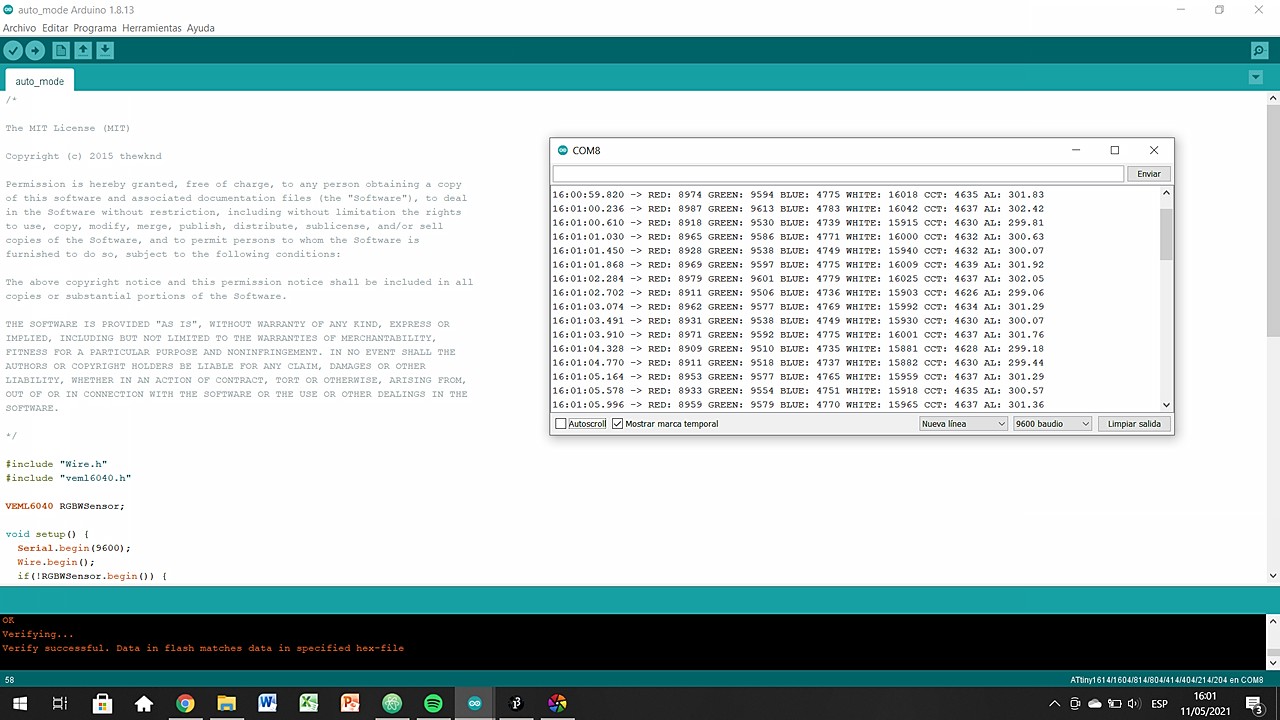
As I mentioned, the data offered by the Arduino IDE is not very attractive or easy to understand. Below I show you the data it offers through the serial monitor.
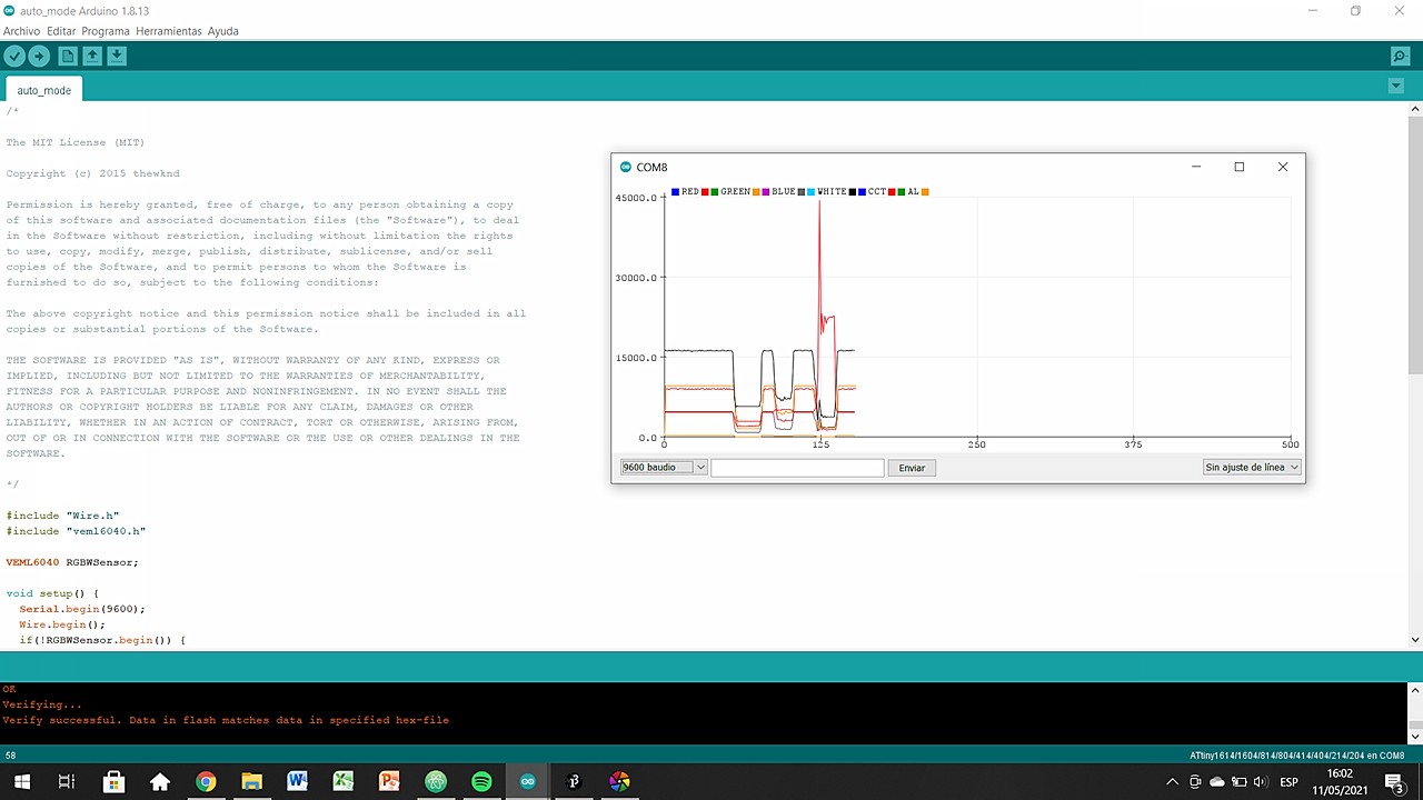
Perhaps the best result you can achieve is the serial plotter, which allows you to see the data in real time as an XY graph. But make no mistake, the data is not visual at all! Hence the need to convert that data into shapes, colors, images that make us better understand what is happening.
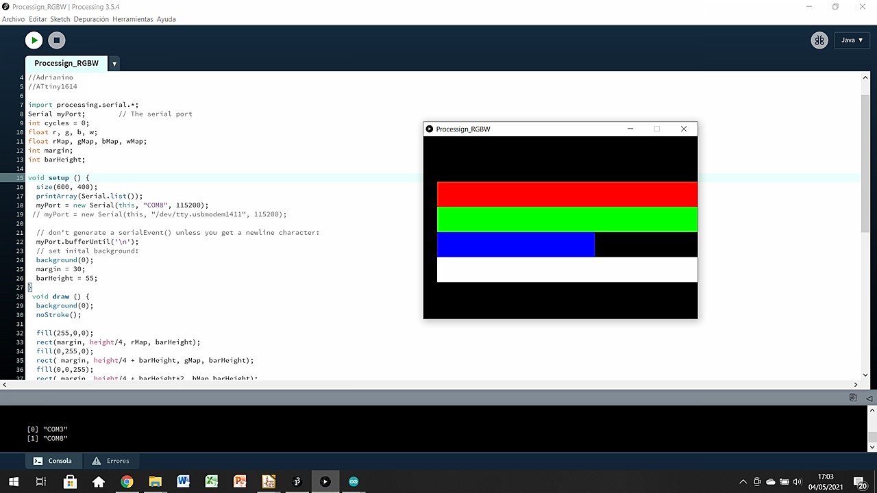
Processing 3
When the system is already flashed and working correctly we can go on to process this data visually. To do this, we jump to Processing and make another code but this time focused on the formal, non-analytical aspects. These analytical data are already given by the Arduino IDE and we only have to convert them into geometries, colors, aspects, ...
//Fab Academy 2021 - Fab Lab Leon
//Adrián Torres & Marta Verde
//Color
//Adrianino (edited by _eneiele)
//ATtiny1614
import processing.serial.*; //import processing serial library
Serial myPort; // The serial port
int cycles = 0;
float r, g, b, w; //Define variables as floats
float rMap, gMap, bMap, wMap; //Define variables as floats
int margin; //Define variables as integral
int barHeight; //Define variables as integral
void setup () { //Start the setup
size(600, 400); //Window sixe inputs: width,height
printArray(Serial.list()); //Create a list
myPort = new Serial(this, "COM8", 115200); //Setting up the port the sensor is connected to
// myPort = new Serial(this, "/dev/tty.usbmo dem1411", 115200);
// don't generate a serialEvent() unless you get a newline character:
myPort.bufferUntil('\n');
// set inital background:
background(0); // black background
margin = 30; // 30 amrgin around the graph
barHeight = 55; // 30 bar height
}
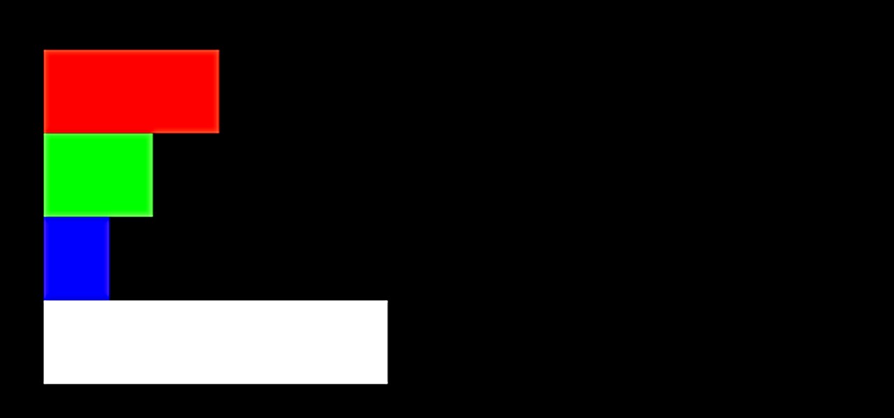
void draw () { //Start the loop=draw
background(0); // black background
noStroke(); // no lines anywhere
fill(255,0,0);
rect(margin, height/4, rMap, barHeight); // create a red rectangle
fill(0,255,0);
rect( margin, height/4 + barHeight, gMap, barHeight); // create a green rectangle
fill(0,0,255);
rect( margin, height/4 + barHeight*2, bMap,barHeight); // create a blue rectangle
fill(255);
rect(margin, height/4 + barHeight*3, wMap, barHeight); // create a white rectangle
/*
if (cycles >= 10) {
cycles = 0;
background(0);
}
cycles++;
*/
}
void serialEvent(Serial myPort) {
String inString = myPort.readStringUntil('\n');
if (inString != null) {
inString = trim(inString);
int[] data = int(split(inString, ",")); //se parte el mensaje con las comas
if (data.length >=4) { //este numero, poner cuantos mensajes se esperan
r = int(data[0]);
g = int(data[1]);
b = int(data[2]);
w = int(data[3]);
rMap = map(r, 0, 6000, 0, height);
gMap = map(g, 0, 6000, 0, height);
bMap = map(b, 0, 6000, 0, height);
wMap = map(w, 0, 6000, 0, height);
}
}
}
What the code is doing in summary form is:
- Get the r,g,b,w information from the serial line in USB
- Map the information into rectangles that grow from 0 to 6000 px in width but with a constant height/4 height
- Read the values and keep the processing live
Here you have a video so you can see how the interface behaves in front of different colors and how the bars grow and decrease according to the color read and the darkness of it.
Original Files
Link to Original files from this week.
What to improve for next assignments?
This week I knew it was going to be very hard for work reasons (my students have final deliveries and that translates into many hours of correcting work and follow-up). Last week I tried to do this week's assignment and I think it was a success. The week has not shone much, but I am happy with the result.
What to keep an eye on during week 16?
· Focus on the final project and take advantage of the wildcard for something useful
· Start the manufacturing of the final project lamp
· Enjoy the process and spend plenty of hours a day working on it (if possible)