WEEK 14: Interface and Application Programming
This week was about programming. We got in touch with different programming languages as well as different softwares and interfaces to make GUIs
For the group assignment we had to compare as many tools to programm and make GUIs as possible
The individual assignment, was to write an application that interfaces a user with and input and output device that we made
Group assignment:
During local classes we were able to get in touch with different platforms.
We focused in Processing and Pj5s and we wrote some examples in both of them in order to see little differences betwen the code we have to use in both of them.
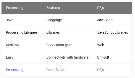
Here is a table where the main features of both of them are shown:

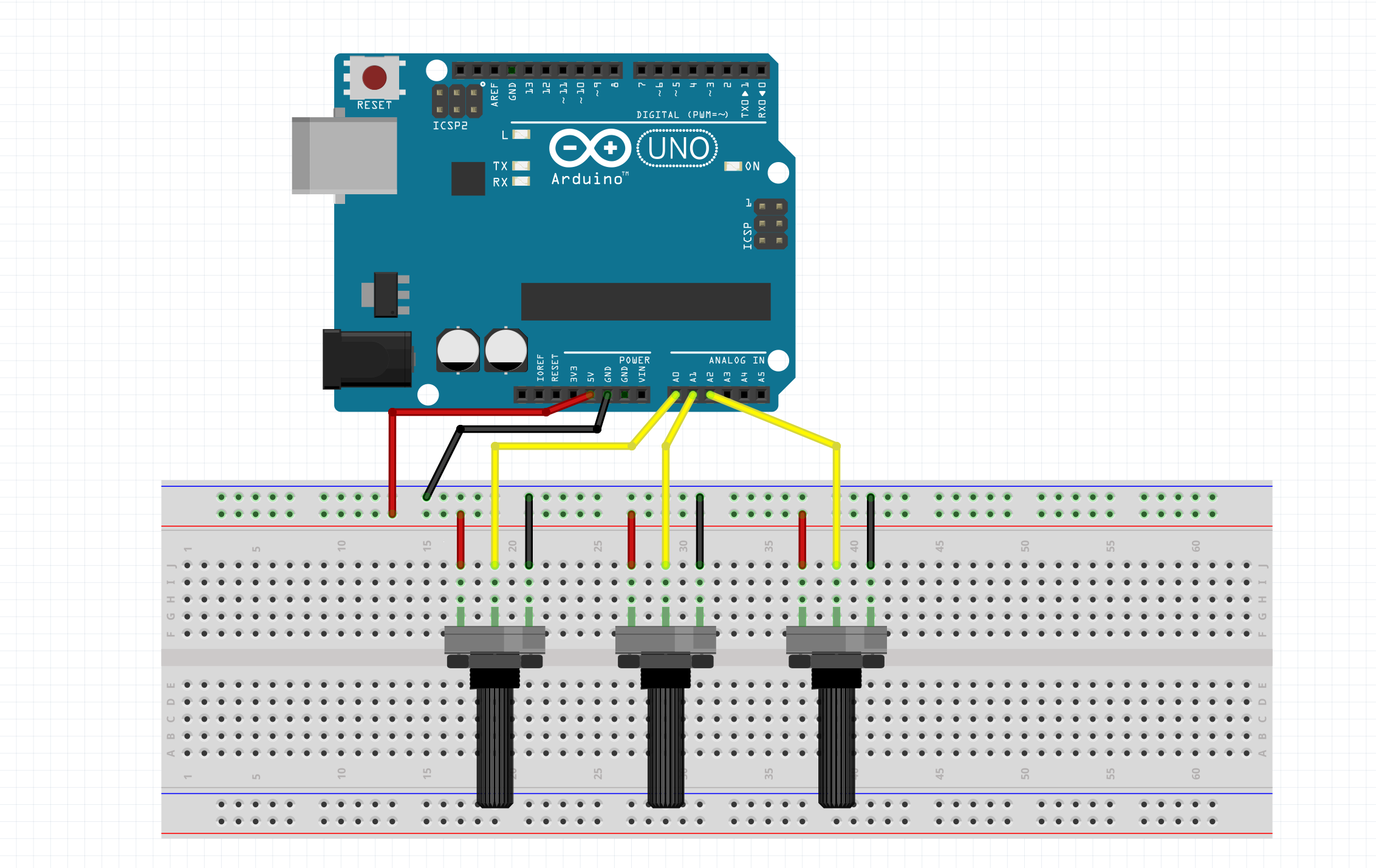
One of the examples we did was controlling the background color of an interface with RGB values provided from 3 potenciometers connected to an Arduino.

This is the code we used in Arduino IDE:
  const int redPin = A0;      // sensor to control red color
  const int greenPin = A1;    // sensor to control green color
  const int bluePin = A2;     // sensor to control blue color

  void setup() {
    Serial.begin(9600);
  }

  void loop() {
    Serial.print(analogRead(redPin));
    Serial.print(",");
    Serial.print(analogRead(greenPin));
    Serial.print(",");
    Serial.println(analogRead(bluePin));
  }
The Processing code:
  import processing.serial.*;

  float redValue = 0;        // red value
  float greenValue = 0;      // green value
  float blueValue = 0;       // blue value

  Serial myPort;

  void setup() {
    size(600, 600);

    // List all the available serial ports
    // if using Processing 2.1 or later, use Serial.printArray()
    println(Serial.list());

    // I know that the first port in the serial list on my mac
    // is always my  Arduino, so I open Serial.list()[0].
    // Open whatever port is the one you're using.
    myPort = new Serial(this, Serial.list()[0], 9600);
    // don't generate a serialEvent() unless you get a newline character:
    myPort.bufferUntil('\n');
  }

  void draw() {
    // set the background color with the color values:
    background(redValue, greenValue, blueValue);
  }

  void serialEvent(Serial myPort) {
    // get the ASCII string:
    String inString = myPort.readStringUntil('\n');
    print(inString);

    if (inString != null) {
      // trim off any whitespace:
      inString = trim(inString);
      // split the string on the commas and convert the
      // resulting substrings into an integer array:
      float[] colors = float(split(inString, ","));
      // if the array has at least three elements, you know
      // you got the whole thing.  Put the numbers in the
      // color variables:
      if (colors.length >=3) {
        // map them to the range 0-255:
        redValue = map(colors[0], 0, 1023, 0, 255);
        greenValue = map(colors[1], 0, 1023, 0, 255);
        blueValue = map(colors[2], 0, 1023, 0, 255);
      }
    }
  }
Video of the interface in Processing:
And the P5js code:
  let serial; // variable for the serial object
  let colors = [0,0,0];

  function setup() {
    createCanvas(windowWidth, windowHeight);
    // serial constructor
    serial = new p5.SerialPort();

    // serial port to use - you'll need to change this
    serial.open('COM5');

    // what to do when we get serial data
    serial.on('data', gotData);

  }

  // when data is received in the serial buffer

  function draw() {
    let red = int(map(colors[0],0,1023,0,255));
    let green = int(map(colors[1],0,1023,0,255));
    let blue = int(map(colors[2],0,1023,0,255));
    background(red,green, blue);
    text(str(red)+"  "+str(green)+"  "+str(blue), width/2,height/2);
  }

  function gotData() {
    let currentString = serial.readLine(); // store the data in a variable
    trim(currentString); // get rid of whitespace
    if (!currentString) return; // if there's nothing in there, ignore it
    colors = split(currentString, ',');
  }
Video of the interface in Pj5:
These are some of the differences in the code between Processing and P5js:
- void setup() in Processing vs function setup() in P5js
- void draw() in Processing vs function draw() in P5js
- size(Width, Height) in Processing vs createCanvas(Width, Height) in P5js
- void serialEvent(Serial myPort) in Processing vs function gotData() in P5js
Individual assignment
For the individual assignment I decided to work with my loved ESP32 board that I made in the Networking and communications week. I had a temperature sensor as input and a LED integrated in the board as an output in order to interact with them.

ESP32 as Web Server:
As the ESP32 has WIFI and I wanted to interact with it through WIFI, I started this week creating a Web Server in the ESP32.
To do so, I followed the local documentation where all the process is explained very well
First of all I flashed my ESP32 in STA mode with the following code:
  /*
    ESP32 Web Server - STA Mode
    modified on 25 MAy 2019
    by Mohammadreza Akbari @ Electropeak
    https://electropeak.com/learn
  */

  #include <WiFi.h>
  #include <WebServer.h>

  // SSID & Password
  const char* ssid = "*****";  // Enter your SSID here
  const char* password = "*****";  //Enter your Password here

  WebServer server(80);  // Object of WebServer(HTTP port, 80 is defult)

  void setup() {
    Serial.begin(115200);
    Serial.println("Try Connecting to ");
    Serial.println(ssid);

    // Connect to your wi-fi modem
    WiFi.begin(ssid, password);

    // Check wi-fi is connected to wi-fi network
    while (WiFi.status() != WL_CONNECTED) {
    delay(1000);
    Serial.print(".");
    }
    Serial.println("");
    Serial.println("WiFi connected successfully");
    Serial.print("Got IP: ");
    Serial.println(WiFi.localIP());  //Show ESP32 IP on serial

    server.on("/", handle_root);

    server.begin();
    Serial.println("HTTP server started");
    delay(100);
  }

  void loop() {
    server.handleClient();
  }

  // HTML & CSS contents which display on web server
  String HTML = "\
  <html>\
  <body>\
  <h1>My First Web Server with ESP32 - Station Mode 😊\
  </body>\
  </html>";

  // Handle root url (/)
  void handle_root() {
    server.send(200, "text/html", HTML);
  }
What the code does, Is tell the ESP32 to connect to the WIFI modem with the SSID and pasword provided. Then, it prints the IP address to wich is connected. In the loop section, is where the html code of the web page is written.
Then I opened the serial monitor and wainted for the microcontroller to connect to the WIFI:

Once I have the IP address, I was able to connect to the web server I just created an see the website.
I connected from my phone and voila!:

The next step I followed, was trying to controll something from the ESP32 web server. To do so, I also followed the local documentation.
The operation behind this, is that when you type a URL in a web browser and hit ENTER, the browser sends a HTTP request to a web server. So the thing is that we can control things by accessing a specific URL, because we are making a specific request and we can tell the microcontroller what to do with each different address request.
For example, to turn a LED on or off I used the following code, that is modified from the original one because I only have one LED:
  #include <WiFi.h>
  #include <WebServer.h>

  /*Put your SSID & Password*/
  const char* ssid = "MIWIFI_sRpM";  // Enter SSID here
  const char* password = "AQc4GrMa";  //Enter Password here

  WebServer server(80);

  uint8_t LED1pin = 13;
  bool LED1status = LOW;

  void setup() {
    Serial.begin(115200);
    delay(100);
    pinMode(LED1pin, OUTPUT);

    Serial.println("Connecting to ");
    Serial.println(ssid);

    //connect to your local wi-fi network
    WiFi.begin(ssid, password);

    //check wi-fi is connected to wi-fi network
    while (WiFi.status() != WL_CONNECTED) {
    delay(1000);
    Serial.print(".");
    }
    Serial.println("");
    Serial.println("WiFi connected..!");
    Serial.print("Got IP: ");  Serial.println(WiFi.localIP());

    server.on("/", handle_OnConnect);
    server.on("/led1on", handle_led1on);
    server.on("/led1off", handle_led1off);
    server.onNotFound(handle_NotFound);

    server.begin();
    Serial.println("HTTP server started");
  }
  void loop() {
    server.handleClient();
    if(LED1status)
    {digitalWrite(LED1pin, HIGH);}
    else
    {digitalWrite(LED1pin, LOW);}
  }

  void handle_OnConnect() {
    LED1status = LOW;
    Serial.println("GPIO4 Status: OFF");
    server.send(200, "text/html", SendHTML(LED1status));
  }

  void handle_led1on() {
    LED1status = HIGH;
    Serial.println("GPIO4 Status: ON");
    server.send(200, "text/html", SendHTML(true));
  }

  void handle_led1off() {
    LED1status = LOW;
    Serial.println("GPIO4 Status: OFF");
    server.send(200, "text/html", SendHTML(false));
  }


  void handle_NotFound(){
    server.send(404, "text/plain", "Not found");
  }

  String SendHTML(uint8_t led1stat){
    String ptr = " <html>\n";
    ptr +="<head><meta name=\"viewport\" content=\"width=device-width, initial-scale=1.0, user-scalable=no\">\n";
    ptr +="<title>LED Control</title>\n";
    ptr +="<style>html { font-family: Helvetica; display: inline-block; margin: 0px auto; text-align: center;}\n";
    ptr +="body{margin-top: 50px;} h1 {color: #444444;margin: 50px auto 30px;} h3 {color: #444444;margin-bottom: 50px;}\n";
    ptr +=".button {display: block;width: 80px;background-color: #3498db;border: none;color: white;padding: 13px 30px;
      text-decoration: none;font-size: 25px;margin: 0px auto 35px;cursor: pointer;border-radius: 4px;}\n";
    ptr +=".button-on {background-color: #3498db;}\n";
    ptr +=".button-on:active {background-color: #2980b9;}\n";
    ptr +=".button-off {background-color: #34495e;}\n";
    ptr +=".button-off:active {background-color: #2c3e50;}\n";
    ptr +="p {font-size: 14px;color: #888;margin-bottom: 10px;}\n";
    ptr +="</style>\n";
    ptr +="</head>\n";
    ptr +="<body>\n";
    ptr +="<h1>ESP32 Web Server</h1>\n";
      ptr +="<h3>Using Station(STA) Mode</h3>\n";

     if(led1stat)
    {ptr +="<p>LED1 Status: ON</p><a class=\"button button-off\" href=\"/led1off\">OFF</a>\n";}
    else
    {ptr +="<p>LED1 Status: OFF</p><a class=\"button button-on\" href=\"/led1on\">ON</a>\n";}

    ptr +="</body>\n";
    ptr +="</html>\n";
    return ptr;
  }
What the code does, is the same as the last one, but in the website we have a button that links to two different addresses, one of them turns the LED on and the other one turns the LED off.
I searched the IP address again, and I connected from my phone so that I was able to control the LED from my phone:
I was also able to see in the serial monitor what was going on:

Making a GUI with Processing:
As I don't have much knowledge about programming, and I've been using Arduino IDE for a while during Fab Academy, I decided to start with Processing in order to interact with my boards.
What I wanted to do was make a GUI that allows me to read a temperature sensor and to turn on and off a LED.
I started with the temperature sensor. First of all, I took the code I used for the SHT35 sensor in the inputs week and I modified it to measure only the tempertaure (not humidity) and to print only the temperature value in the serial monitor.
So I flashed the following code in my ESP32 with Arduino IDE:
  #include <Arduino.h>
  #include <Wire.h>
  #include "Adafruit_SHT31.h"

  bool enableHeater = false;
  uint8_t loopCnt = 0;

  Adafruit_SHT31 sht31 = Adafruit_SHT31();

  void setup() {
    Serial.begin(9600);

    while (!Serial)
      delay(10);     // will pause Zero, Leonardo, etc until serial console opens

    Serial.println("SHT35 test");
    if (! sht31.begin(0x45)) {   // Set to 0x45 for alternate i2c addr
      Serial.println("Couldn't find SHT35");
      while (1) delay(1);
    }
  }


  void loop() {
    float t = sht31.readTemperature();

    if (! isnan(t)) {  // check if 'is not a number'
      Serial.println(t);
    } else {
      Serial.println("Failed to read temperature");
    }

    delay(1000);
  }
And I checked I was getting proper values:
Then I run into processing.
I just needed to downloaded from the website and run it, no need to install anything.
I started from an example in the local documentation where it is explained how to measure a LDR sensor and show the data in the screen.
So I took that code and I modified it to print the temperature from the sensor in the screen.
Some of the modifications I had to make in order to make it work were for example working with string instead of integer or convert the value to a float value as it is in the Arduino Code.
  import processing.serial.*;
  String lecture = null;
  int lf = 10;
  float temp;
  Serial myPort;

  void setup() {
    size(700, 400);
    myPort = new Serial(this, "COM6", 9600);
    myPort.clear();
  }

  void draw() {
    while (myPort.available() > 0) {
      lecture = myPort.readStringUntil(lf);
      if (lecture != null) {
          print(lecture);  // Prints String
          temp=float(lecture);  // Converts and prints float
          println(temp);
          }
    }

    background(20);
    textSize(40);
    text("Temp:"+temp+"ºC", 200, 200);
    myPort.clear();
  }
The program just shows the read value in the screen.
The next step was trying to interact with an output. As I have an LED in my board, I decided to try to turn it on and off with an interface made it with Processing.
To do so, I just took an example called "Simplewrite" where codes for both Processing and Arduino IDE are provided.
In case of the Arduino code, I just had to set the pin where the LED is connected:
  // Wiring/Arduino code:
  // Read data from the serial and turn ON or OFF a light depending on the value

  char val; // Data received from the serial port
  int ledPin = 13; // Set the pin to digital I/O 4

  void setup() {
  pinMode(ledPin, OUTPUT); // Set pin as OUTPUT
  Serial.begin(9600); // Start serial communication at 9600 bps
  }

  void loop() {
  while (Serial.available()) { // If data is available to read,
  val = Serial.read(); // read it and store it in val
  }
  if (val == 'H') { // If H was received
  digitalWrite(ledPin, HIGH); // turn the LED on
  } else {
  digitalWrite(ledPin, LOW); // Otherwise turn it OFF
  }
  delay(100); // Wait 100 milliseconds for next reading
  }
And then in Processing I setted the port where the board was connected
  import processing.serial.*;

  Serial myPort;  // Create object from Serial class
  int val;        // Data received from the serial port

  void setup()
  {
    size(200, 200);
    // I know that the first port in the serial list on my mac
    // is always my  FTDI adaptor, so I open Serial.list()[0].
    // On Windows machines, this generally opens COM1.
    // Open whatever port is the one you're using.
    String portName = Serial.list()[0];
    myPort = new Serial(this, "COM6", 9600);
  }

  void draw() {
    background(255);
    if (mouseOverRect() == true) {  // If mouse is over square,
      fill(204);                    // change color and
      myPort.write('H');              // send an H to indicate mouse is over square
    }
    else {                        // If mouse is not over square,
      fill(0);                      // change color and
      myPort.write('L');              // send an L otherwise
    }
    rect(50, 50, 100, 100);         // Draw a square
  }

  boolean mouseOverRect() { // Test if mouse is over square
    return ((mouseX >= 50) && (mouseX <= 150) && (mouseY >= 50) && (mouseY <= 150));
  }
What it does, is that it sends a High ("H") or Low ("L") signal through the serial port to the microcontroller, depending on if the mouse is over a rectangle or not. The microcontroller knows what to do in each case because we told him so with the code we've flashed.
And it worked:
The next and last challenge was obvious: to make an interface where I was able to read the temperature and also turn on and off the LED with a button
To do so, I just mixed the two codes, with some adjustments.
The Arduino code:
  #include <Arduino.h>
  #include <Wire.h>
  #include "Adafruit_SHT31.h"

  bool enableHeater = false;
  uint8_t loopCnt = 0;
  char val; // Data received from the serial port
  int ledPin = 13; // Set the pin to digital I/O 4

  Adafruit_SHT31 sht31 = Adafruit_SHT31();

  void setup() {
    Serial.begin(9600);
    pinMode(ledPin, OUTPUT); // Set pin as OUTPUT

    while (!Serial)
      delay(10);     // will pause Zero, Leonardo, etc until serial console opens

    Serial.println("SHT35 test");
    if (! sht31.begin(0x45)) {   // Set to 0x45 for alternate i2c addr
      Serial.println("Couldn't find SHT35");
      while (1) delay(1);
    }
  }


  void loop() {
    float t = sht31.readTemperature();

    if (! isnan(t)) {  // check if 'is not a number'
      Serial.println(t);
    } else {
      Serial.println("Failed to read temperature");
    }
    Serial.flush();
    delay(1000);

  while (Serial.available()) { // If data is available to read,
   val = Serial.read(); // read it and store it in val
   }
   if (val == 'H') { // If H was received
   digitalWrite(ledPin, HIGH); // turn the LED on
   } else {
   digitalWrite(ledPin, LOW); // Otherwise turn it OFF
   }
   delay(100); // Wait 100 milliseconds for next reading
   }
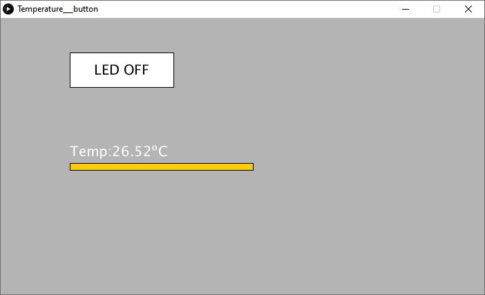
In Processing, I found a way to make a propper button that responds to the click of the mouse. I also designed a bar that varies in length with the temperature measurement, wich is just a rectangle where the width is the value of the measurement multiplied by 10.
The Processing code:
  import processing.serial.*;
  String lecture = null;
  int lf = 10;
  float temp;
  float x = 100;
  float y = 50;
  float w = 150;
  float h = 50;
  int val;


  Serial myPort;

  void setup() {
    size(700, 400);
     background(255);
     stroke(0);
     noFill();
    myPort = new Serial(this, "COM6", 9600);
    myPort.clear();
  }

  void draw() {
    while (myPort.available() > 0) {
      lecture = myPort.readStringUntil(lf);
      println(temp);
      if (lecture != null) {
          print(lecture);  // Prints String
          temp=float(lecture);  // Converts and prints float
          }
    }

    background(180);
    fill (255,204,0);
    rect(100,210,temp*10,10);
    fill(255);
    textSize(20);
    text("Temp:"+temp+"ºC", 100, 200);
    rect(x,y,w,h);
    fill (0);
    text("LED OFF", x+35, y+32);
    if(mousePressed){
        if(mouseX>x && mouseX <x+w && mouseY>y && mouseY <y+h){
         myPort.write('H');
         fill(0);
         rect(x,y,w,h);
         fill (255);
         text("LED ON", x+35, y+32);
               }
                  }
         else {
            myPort.write('L');
    }

  }
The final result:

Video of the inteface working with the temperature sensor and the button to turn on the LED in the board:
Conclusions:
This is my first time doing any kind of interface, and I'm still getting in touch with programming, that's why I decided to start with Processing, because I've been working with C in Arduino for a while during FabAcademy and I prefer to learn it a bit more before jumping to another language.
As I've been told, if you are comfortable with Arduino IDE it's so likely that you are comfortable with Processing, because the language is so similar, and I was able to make things work from the first minute, and that's so satisfiying.
The next step I want to achieve is to show the values of some sensors in the web server in order to be able to see them from any device connected to the same WIFI or even from remote. I'll keep working on that for my final project.