Week 7:
Computer-Controlled Machining
I know that every week I start my introductions with "I can finally use ..." or "I'm very excited to try ...", but believe me this week is very serious. The CNC has been one of the things that I could not try at my university for various reasons, but which I think is one of the most powerful things for an industrial designer.
Depending on your design, it is very likely that by making a few changes to adjust it to CNC, you can prototype your products with industrial finishes. These machines are not cheap, but many studios have made the investment due to the many possibilities it offers.
Specifically in the furniture sector, these machines are unrivaled. Laser cutting or 3d printing (the other two Big Three) cannot compete in terms of materiality, size and repeatability.
I think this week promises to be one of the most fun for me, by far. The weeks of electronics are hard, because I don't have much knowledge, but in this I feel like a fish in water !!!
The three assignments for this week are:
Group assignment:
• Do your lab's safety training
• Test runout, alignment, speeds, feeds, materials, and toolpaths for your machine
Individual assignment:
• make (design+mill+assemble) something big (~meter-scale)
Safety Course
I think the safety course is one of the most important parts of this week's learning. That is why I place it in the first position within the website of the week.
Our instructors Edu and Josep showed us all the steps to follow for a correct and safe use of the machine. In order not to lengthen this section excessively, below you have a list of the most relevant aspects.
Step by step guide
- Disassamble the dust collector
- Unscrew collet
- Clean collet and socket
- Check the end mill is longer than the material
- Attach the end mill (don't trap the flute)
- First fix by hand than with tools (super tight)
- Assemble the dust collector
- Move the router away from you
- Attach the material
- Set origins (aling X than Y) (Z better in the middle of the board)
- Set software
- Start milling
- After a couple cuts stop
- Check end mill temperature, chips and sound
- If everything is fine, keep milling
- Move the drill away from you when it is done
- Take the parts out
- Vacuum the surface and Clean!
- Unscrew the endmill and collet
Safety Golden Rules
Those are the steps to follow when using the machine, but there are some safety rules to always remember while working.
- Hands on the back while milling
- Stay behing the bridge (if the end mills brakes, it won't hit you)
- Know where the emergency buttons are
- Mainly use the computer (the wireless controller doesn't give feedback)
- Safety glasses
- Don't use pen drive. Will eventually disconnect and turn into weird movements
- Only one person works in the bed and in the computer (can't hit anybody if nobody around)
Group Assignment
To do the group assignment this week, we had to organize ourselves as a group better than ever. There is only one CNC in our Fab Lab and we are around 10 people to use it during the week. That together with the long preparation times that these machines require, have made us work very coordinated.
What we want to understand during this week are the parameters to take into account when cutting with CNC Routers. These machines are complex due to the great variety of ways of approaching work with them. As this week we will focus on 2.5D, we want to understand the following parameters:
- Types of end mills
- Feed Speed/Cut Depth/Step Over
- Cutting side tolerance
- Pocketing side tolerance + diameters
- Pocketing depth tolerance
- Climb vs. Conventional
- Along wood fiber vs. Across wood fiber
Now that we have outlined the general structure of the group assignment for week 7, it is time to deal with all the previous points one by one.
Types of end mills
There are 4 general types of drill bits for use on CNC machines. Each one has its strengths, weaknesses and parameters to take into account. Those four types are:
- Straight: good overall, but may produce less good surface finishes
- Down: porr chip removal, can't drill holes, may tear put last layer, slower feed rate
- Up: great chipp removal, can tear-out the top. Can drill holes easily
- Compression: combination of up and down, great al around, great for laminated materials
It is almost impossible to say which of the four big guys is the best or the worst. In the end it all comes down to personal experience and the characteristics of the material. Knowing their general behaviors, it is the designer / maker's job to choose the best end mill.
Another of the most relevant characteristics of end mills is the amount of flutes they have. In broad strokes, the number of flutes and the feed rate grow directly proportionally. The more flutes the more material we can move and the faster it can rotate.
Feed Speed/Cut Depth/Step Over
The feed speed depends on the following expression:
Chip load = x (inch per minute)speed/ (rpm of the motor * n flutes)
End mill manufacturers accompany their products with a small table of chip loads for you to carry out the necessary conversions. As you can see in the following image, it all depends on the diameter of the bit and the material to be cut. Taking this data into account, we only need to isolate the X to obtain a suitable value of feed rate.
Other characteristics to take into account are: the cut depth and the step over. These two parameters must be respected in order not to exceed the force that the end mill can withstand. Going short is not a problem, but overdoing it can cause the bit to break spinning at 20000rpm.
Cut depth = tool diameter/2
Step-over= tool diameter/2
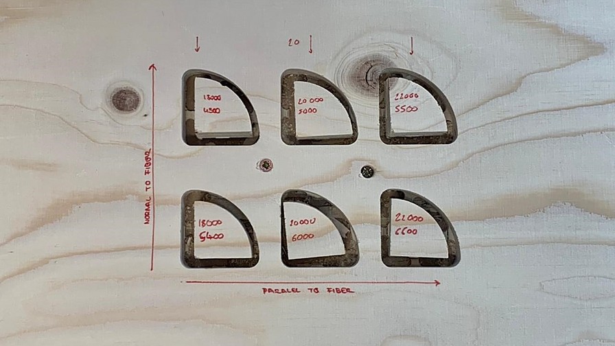
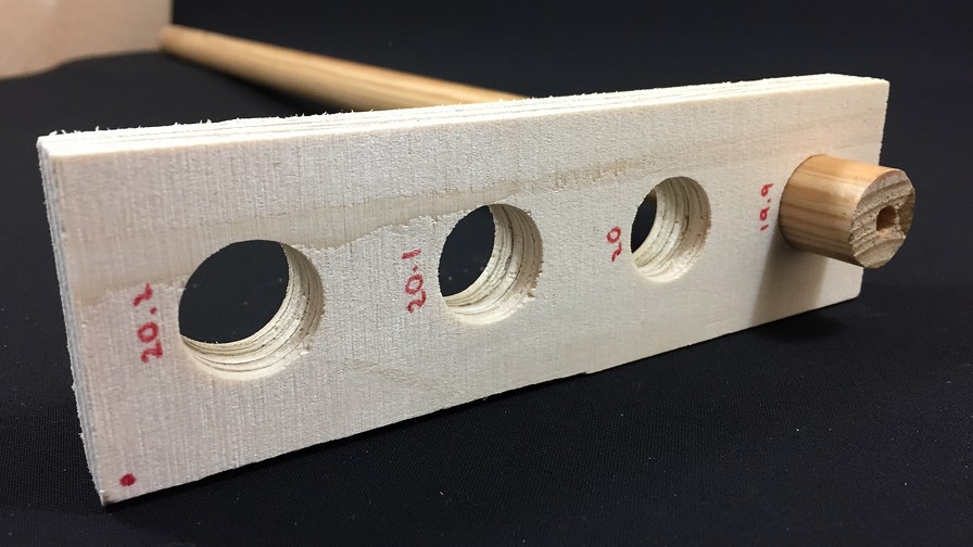
Cutting side tolerance
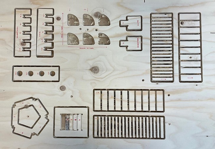
For the following points, we developed a small test sheet as a team to try to find out the geometric tolerances that we should respect in our designs.
As you will see later, the tolerances have been incredible. The difference between the techniques is almost negligible and they closely match the dxf data. One thing to keep in mind is that the wood we use is very soft so it is easy to force the joints to achieve perfect adjustments.
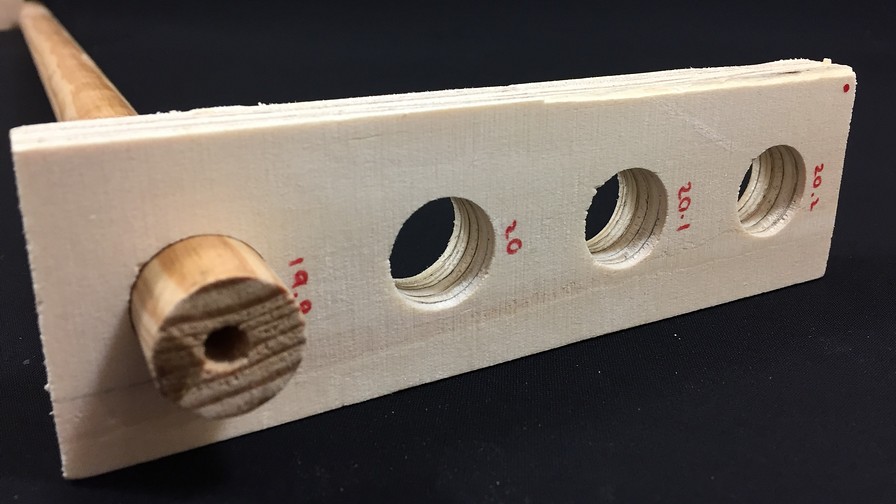
Pocketing side tolerance + diameters
Cutting and pocketing have worked in much the same way: incredibly small tolerances. My colleague Den who cut her model from the first ones, managed to make perfect laces leaving tolerances of 0mm.
Pocketing depth tolerance
The depth tolerances are great. We consider these to be less than 1 / 100mm. When doing the tests with the test objects, it is impossible to decide what tolerance it presents. The best option we consider is not to leave any tolerance in this case.
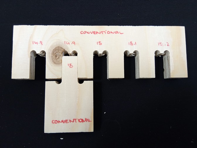
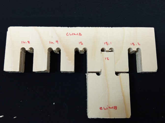
Climb vs. Conventional
In this case, we once again have the dilemma that already arose during the PCB manufacturing week: to work in climb or conventional.
With climb and conventional it is curious because we could not observe appreciable differences. Perhaps the climb by increasing the chip size has been a bit more aggressive in the corners than the conventional one. Speaking with our instructors, they told us that with a material as soft as layered plywood, it is difficult to appreciate big differences.
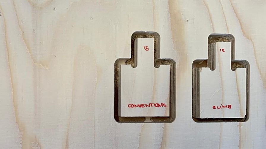
Commenting with them later in the week they told us that the climb is more suitable for up bits and instead the conventional for down bits. Always trying to find the balance between moving material, but not breaking it.
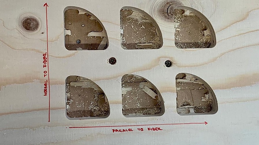
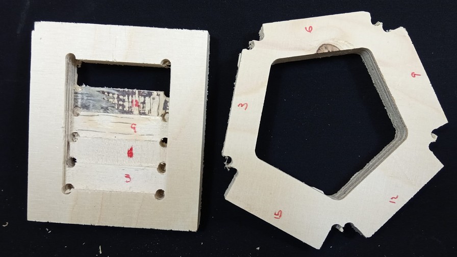
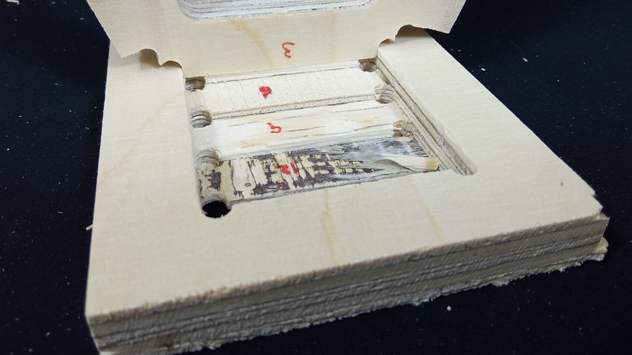
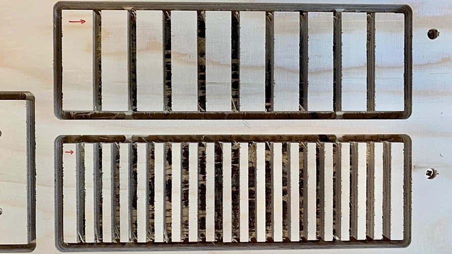
Alongside wood fiber vs. Across wood fiber
This parameter is something that we must take into account even if we do not cut with CNC, but it is interesting to see how it behaves with this type of machine. For this we made the comparison trying to make flexible pieces.
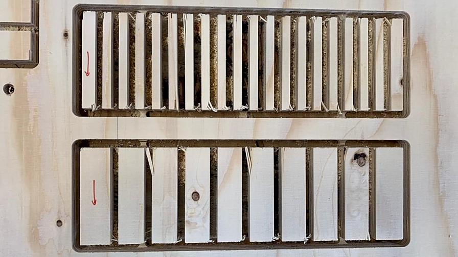
Working along the fiber the tenacity of the material is much better. It is important to note that wood is not an isentropic material so directionality is important. In our specific case, the performance was much better in this direction since the fiber provides resistance to the material.
In contrast, working against fiber, the toughness of the material is incredibly lower. This one almost breaks with touching it. Also one of the factors to take into account is the quantity of chips that are generated. Fiber cuts result in poorer surface finishes because the fibers break when hitting the end mill.
Final conclusions
In order not to dwell too much on the conclusions of the test we did, below you will find the most relevant conclusions in a summarized way:
- The choice of the type of end mill depends on the project.
- You must always keep in mind the manufacturer's parameters in terms of chip load.
- The tolerances strongly depend on the material to be cut. As softer, easier to work with.
- Climb is best for hard materials and conventional for soft materials.
- Taking advantage of the fiber of the material will achieve better mechanical properties.
- Cutting against fiber with soft materials can cause breakage in parts.
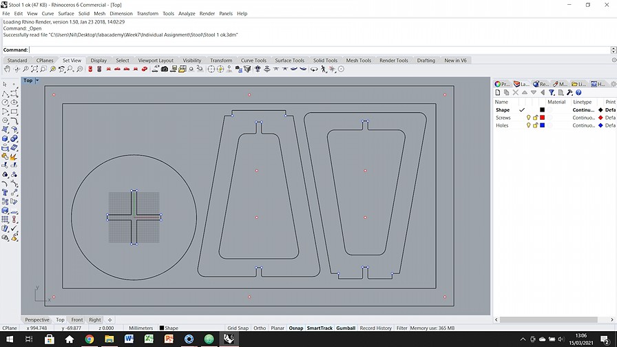
- (Black) Shapes to mill on the CNC.
- (Red) Position of the screws that will secure the plate.
- (Blue) Dog ear position, to avoid rounded corners.
- Move the spindle away from the work area. Safer and more comfortable.
- Place the board in the cutting position.
- Open the socket and place the bit tightly. Make sure it is securely attached, you don't want it to fly off.
- Move the spindle with the computer, to the X, Y origin position you want to use. Use the automatic Z set being careful to be within the button's action zone.
- Safety glasses on, activate the vaccum and back to the computer.
- Load the g-code file from screws and launch it.
- Move the spindle back away from your position and set the screws with the electric drill.
- Upload the pocketing and outcut files at the same time. As I use the same drill they can be done one after the other.
- Stay away from the spindle while cutting, always trying to be in a position where you don't see the bit. If you don't see it, it won't be able to hit you if it lets go.
- Once it has finished, move the spindle away again and if you can turn off the machine.
- Before loosening the wood plank from the screws, break the wood fasteners with a hammer and cutting tool.
- Remove the parts, set them aside and remove the screws with the electric drill.
- Remove the plank.
- Clean the surface with the vacuum cleaner, turn off the vacuum and remove the endmill from the machine.
Individual Assignment
For this week I want to let myself go and do a complex project. For this I have thought that I would like to make a rocking chair! In my house we are lovers of these chairs and almost in every house we have at least one of these. It is a kind of family tradition, to have a rocking chair at home.

Of all the possible rocking chairs on the market, my favorite is the Gaivota by Reno Bonzon 1988. I find it marvelous both visually and from a storytelling point of view. In order not to get into potential copyright issues, I want to make it clear that this is a CNC-centric redesign, for my personal use only.
Why this design?
I have been in love with this chair for years, but its enormous price has never even allowed me to sit in one. I find it beautiful, elegant and subtle. The storytelling that you are watching a seagull fly from a boat window makes me have goosebumps.

I love that it is a huge chair, but feels light and floaty. As you can see in the simple drawings above, it measures 1.1m long by almost 0.6m wide. It will be a personal challenge to redesign and manufacture this chair. I think it's the biggest project I've ever done on a personal level.
Design Process in Rhino6
I have to confess that another reason is that before the Fab Academy, I had already thought that this chair can be easily replicated with the stacking method. During the week of laser cutting, I already thought about doing it, but the cardboard did not give me confidence in terms of mechanical resistance.
To draw the chair in Rhino, I just need to copy the image from the drawings and trace the curves on the photo. It was not a difficult task, but it was somewhat laborious.
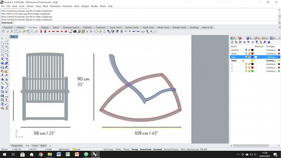
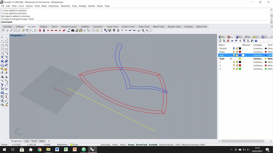
The design is summarized in two basic pieces replicated over and over again, until the necessary thickness of each module is reached. These two pieces are: skate (red) and seat (blue).
First 1:4 scaled model
On Friday at noon I had the model ready and I scale it 1: 4 to check its stability and manufacture. In order not to waste wood, I generate the following scale correspondence table, to find a midpoint of scaled geometries.I believe this is a good way to test things before jumping towards the big CNC.
| Original item | Scaled item | Scale |
|---|---|---|
| 15mm plywood | 4mm cardboard | 1 : 3.75 |
| 20mm pine stick | 6mm beech stick | 1 : 3.33 |
With the above scales in mind, I scale the model with a 1: 3.5 scale to cut the pieces on the laser cutter.
After some adjustments and tolerances to take into account, since the laser and the CNC do not respond the same, I cut the scaled pieces.
Problems and Plan B: wood saving stool
Due to major problems with my job, I have had to change my plans no matter how much it hurts. The week has been getting worse little by little and I don't have time enough to complete the Gaivota during this week's challenge. Instead, I'm going to make a simple stool to cover the file.

My idea is still to finish the Gaivota during the Fab Academy, but this week it is impossible for me. I hope to have a little more peace of mind during the next few months and to be able to finish the project. This has already become a personal challenge that I want to meet no matter what.
Design Process 2
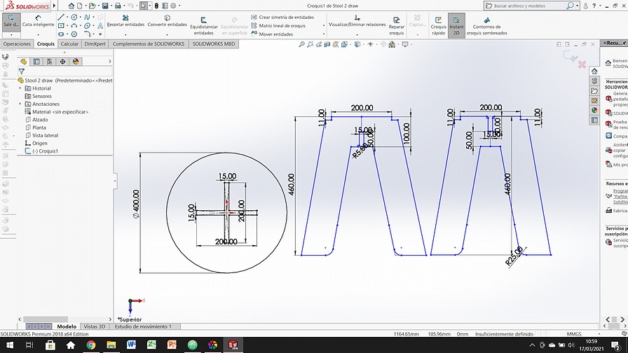
This second design does not motivate me as much as the rocking chair, but it is much simpler and uncomplicated at first glance. I prefer to deliver something this week that shows my skills and in the future weeks to be able to enjoy with the rocking chair.
Instead of drawing in Rhino, this time I worked in Solidworks because it was easier for me to take into account the tolerances and measurements in that software. Below this paragraph you will find some images of how I made the dxf.
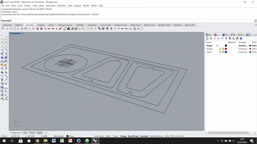
Once ready in Solidworks I import them into Rhino to prepare the worktable and all the necessary fixings to cut safely. Once in Rhino I generate three layers of work for the following functions:
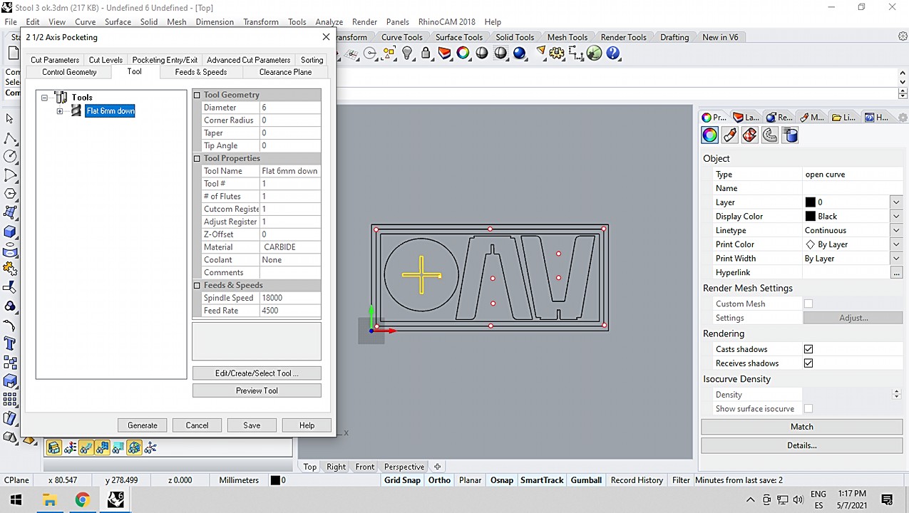
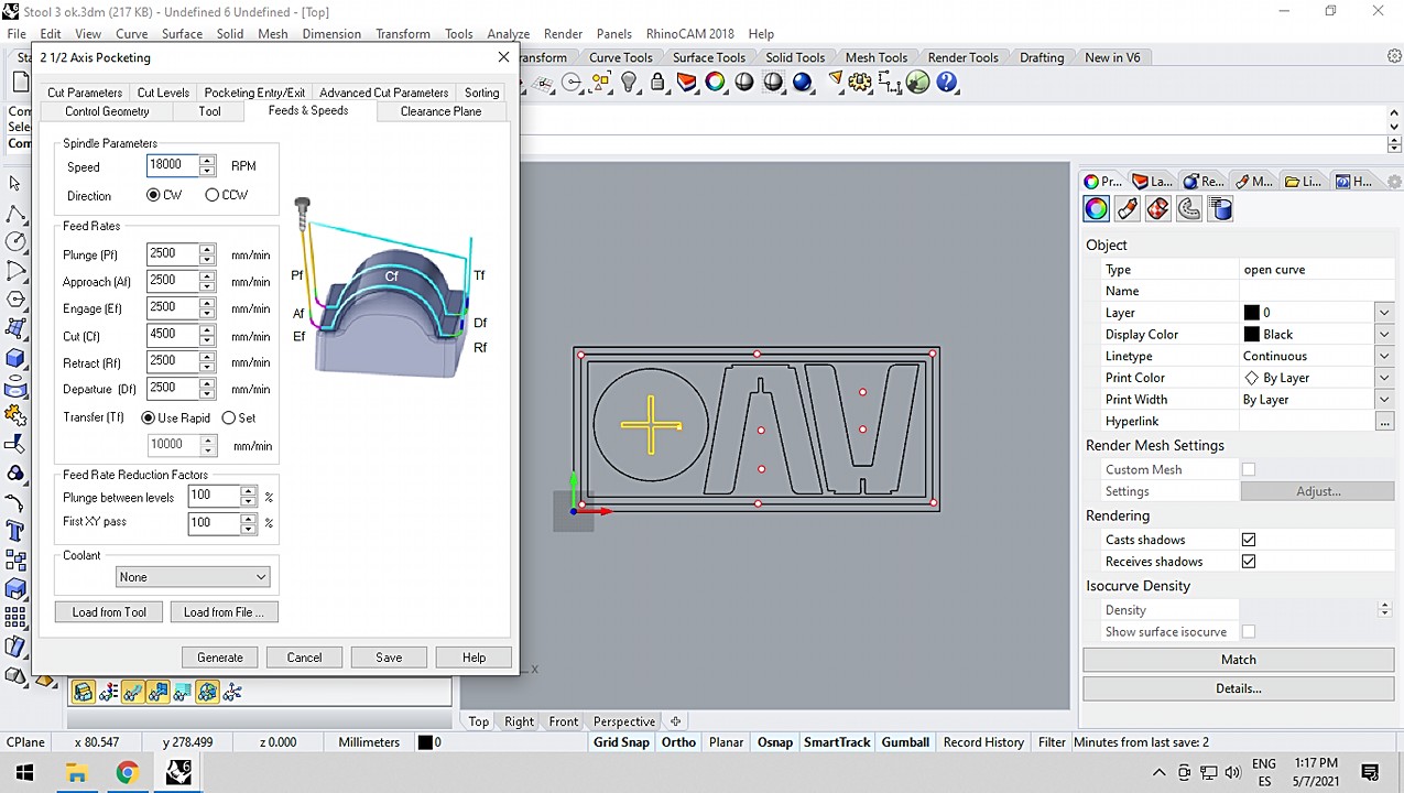
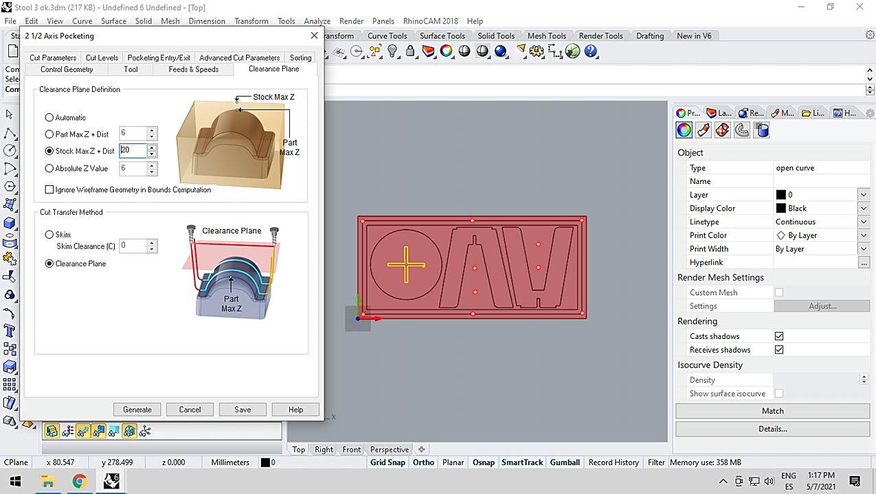
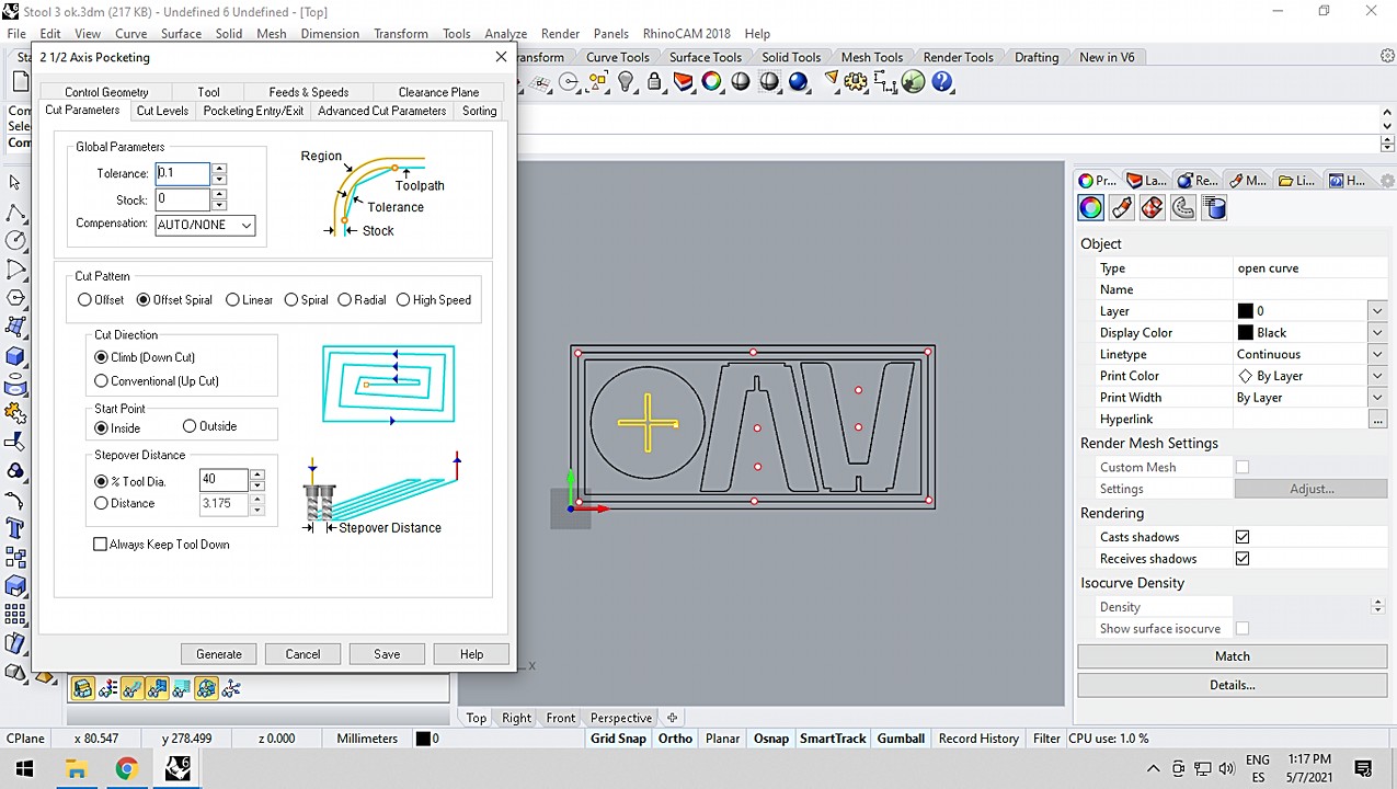
Prepare G-code with RhinoCAM
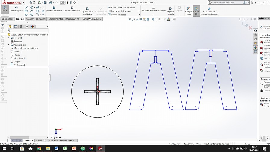
While I was preparing the documents with RhinoCAM I realized that the stool could not be mounted! At that time I had to redo the design and simplify it so that it was possible to assemble. The process was the same as with the wrong design, but I had to do it in just 30 minutes. The shifts to use the machine have been short this week. We are many and there is only one machine.
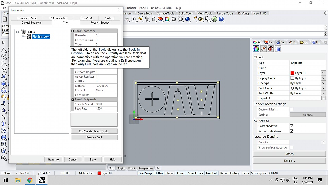
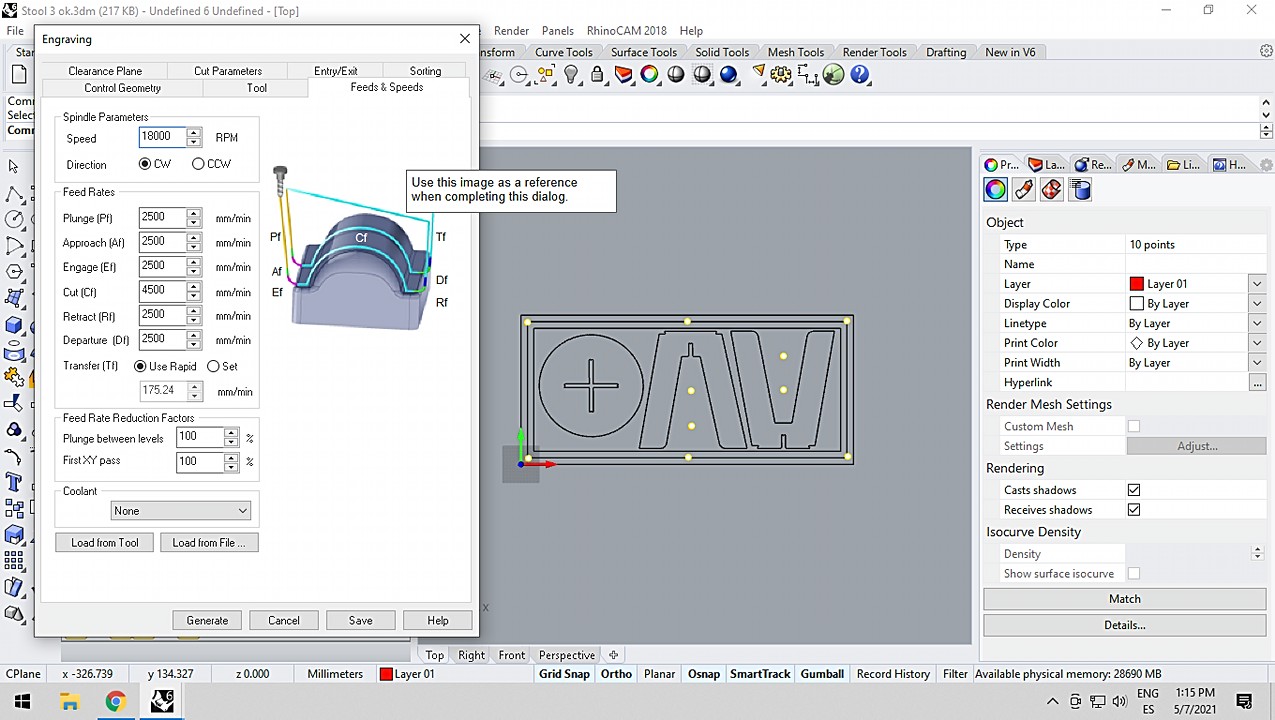
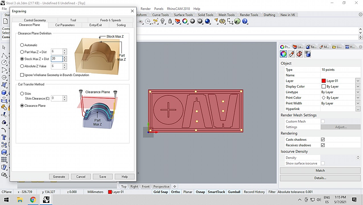
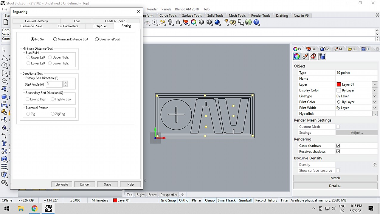
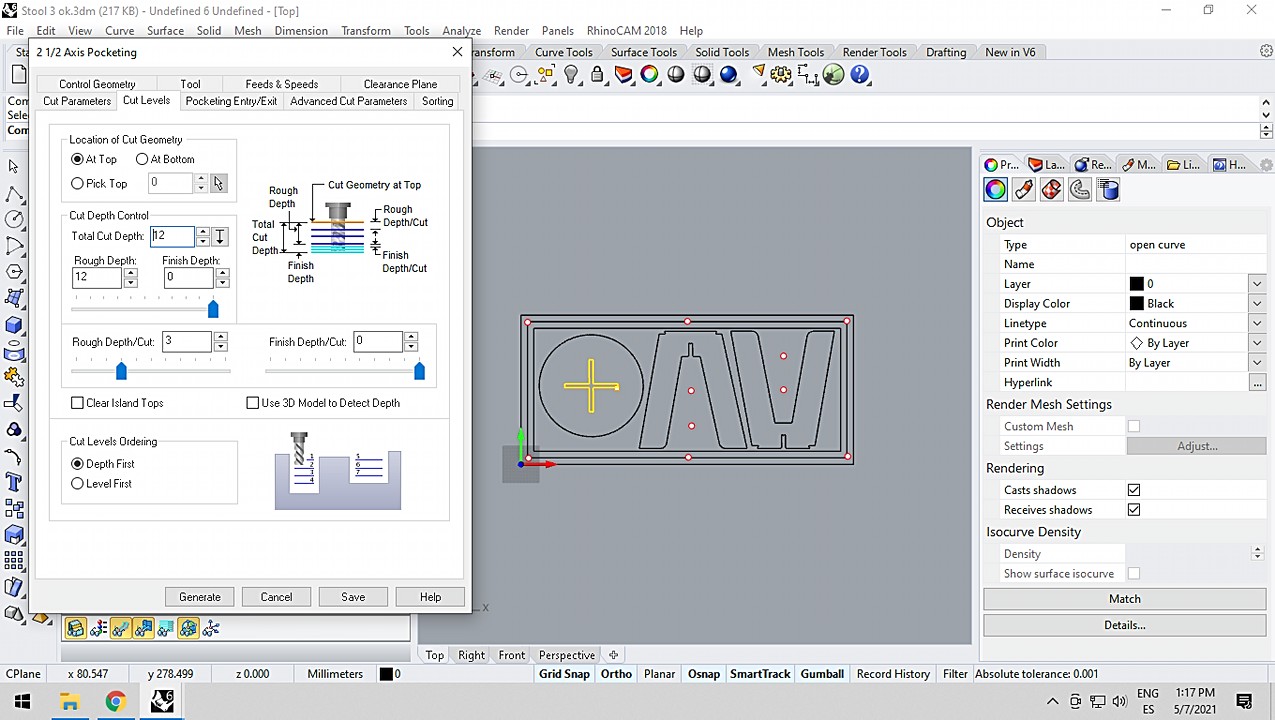
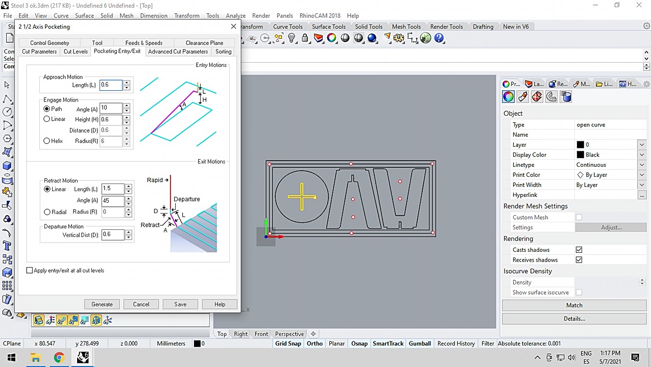
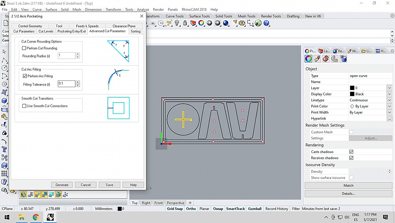
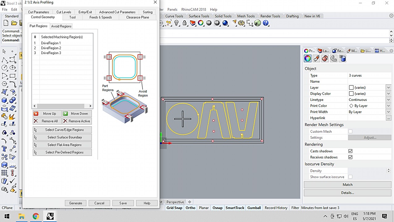
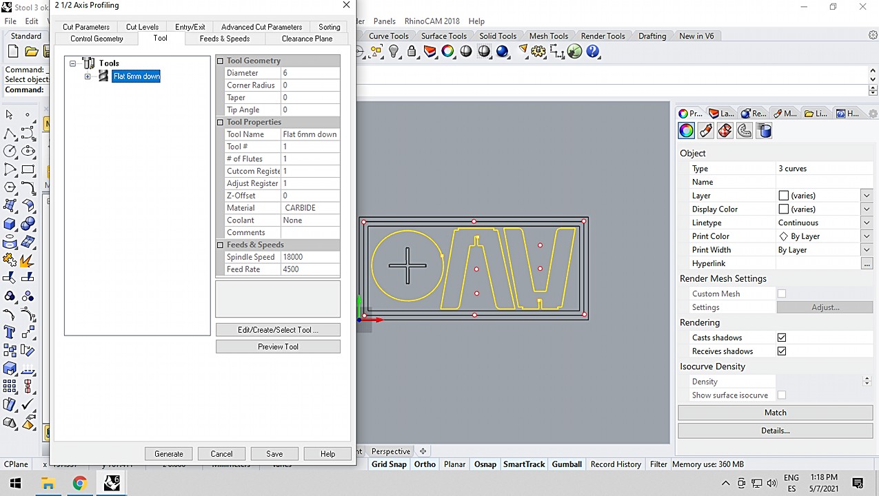
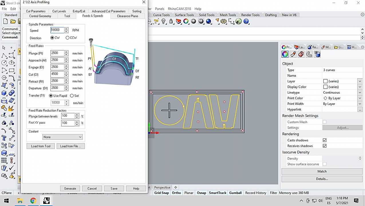
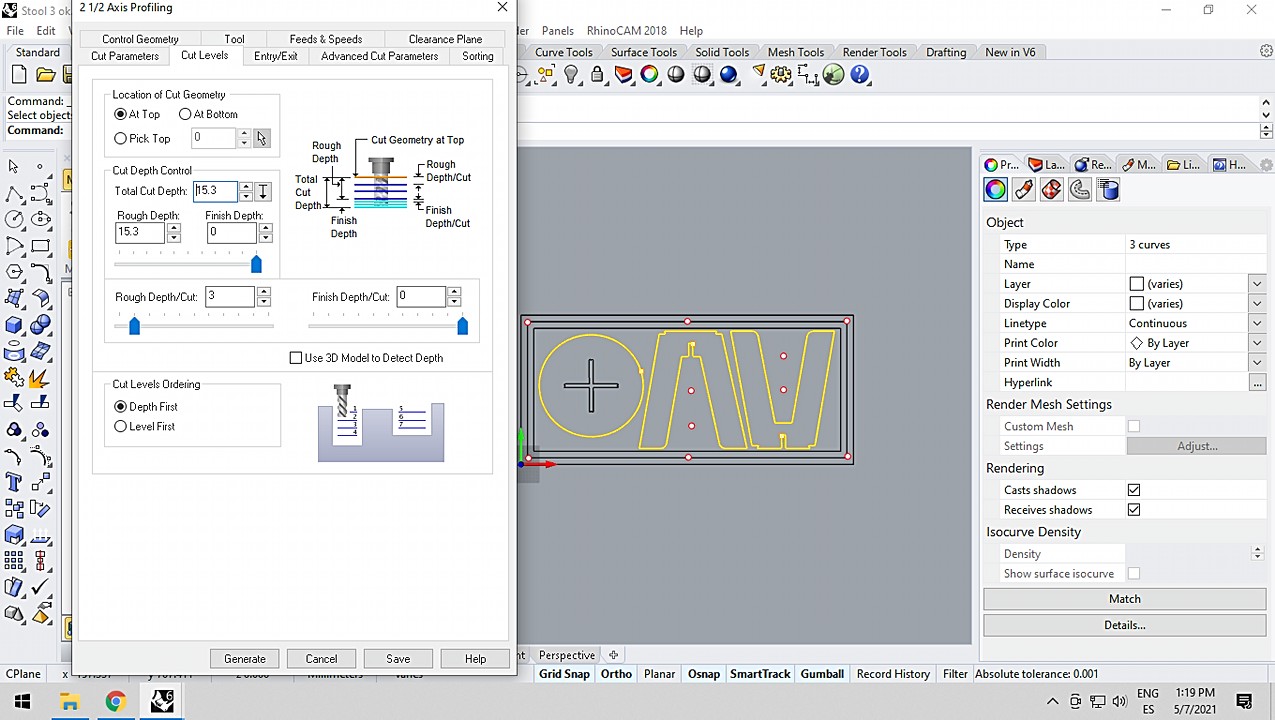
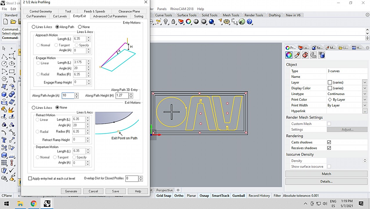
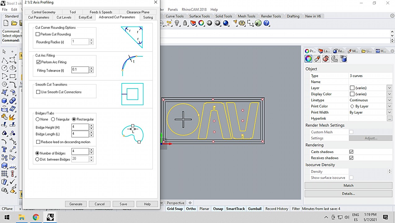
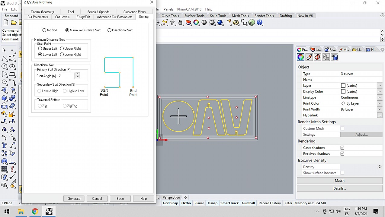
Once the design was ready and free of design errors, I open RhinoCAM and we prepare the files little by little so that the CNC correctly cuts the plank. For you to follow me a little better in the process, I will show you screenshots of the program and I will comment on what I do in each one. Take the opportunity to review all the information about the settings used in the screenshots.
I have prepared the CAM document in three totally different steps. Then I explain them a little better separately.
Screws
To anchor the board to the sacrificial board, we have to know where the screws will be placed. For this reason and taking advantage of the fact that the wooden boards are very heavy, we prepare a file with only a few small non-through holes. This is where we will put the screws before starting with the other more aggressive programs.
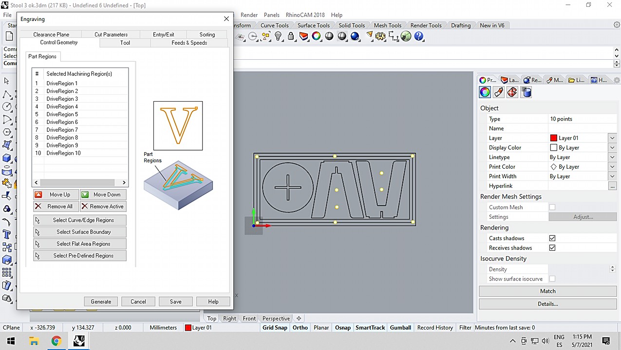
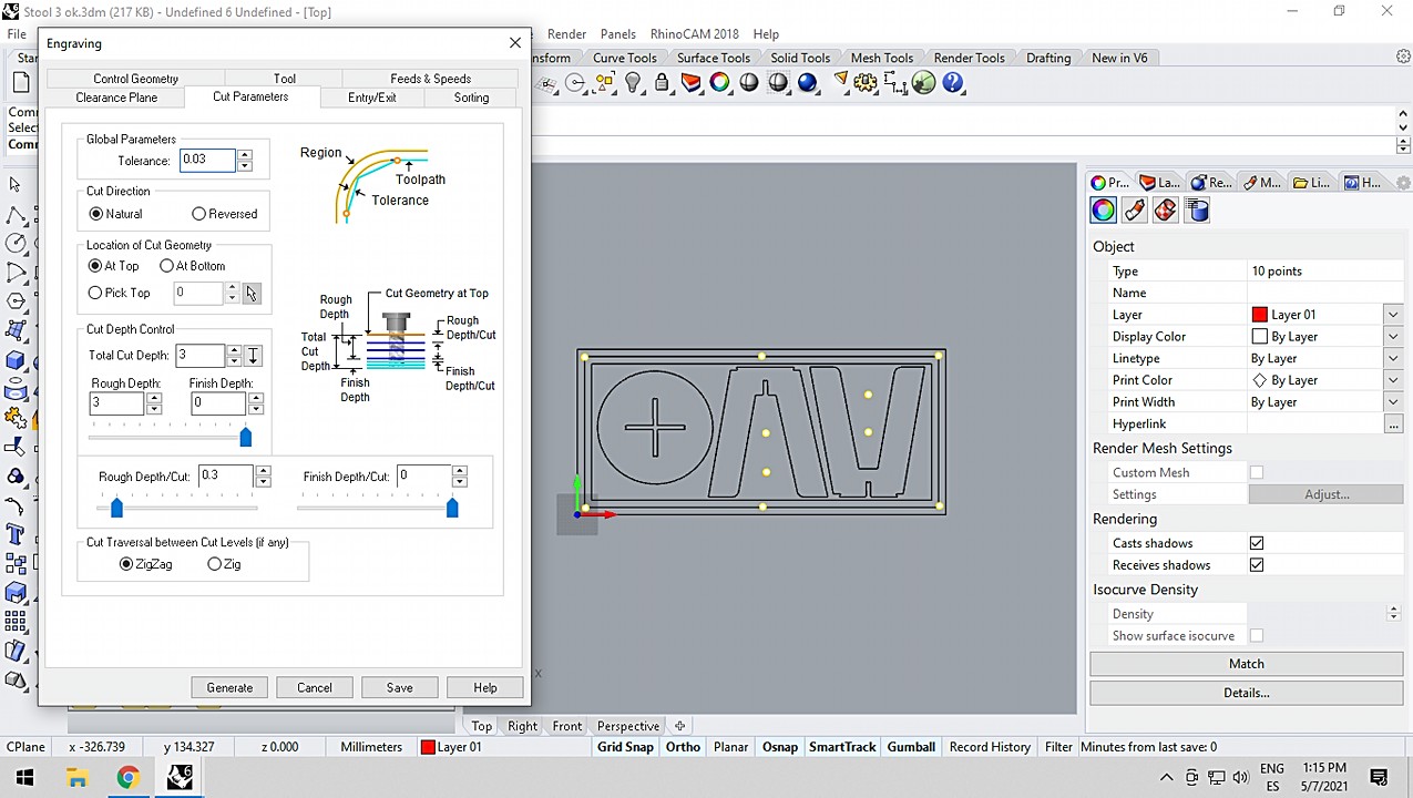
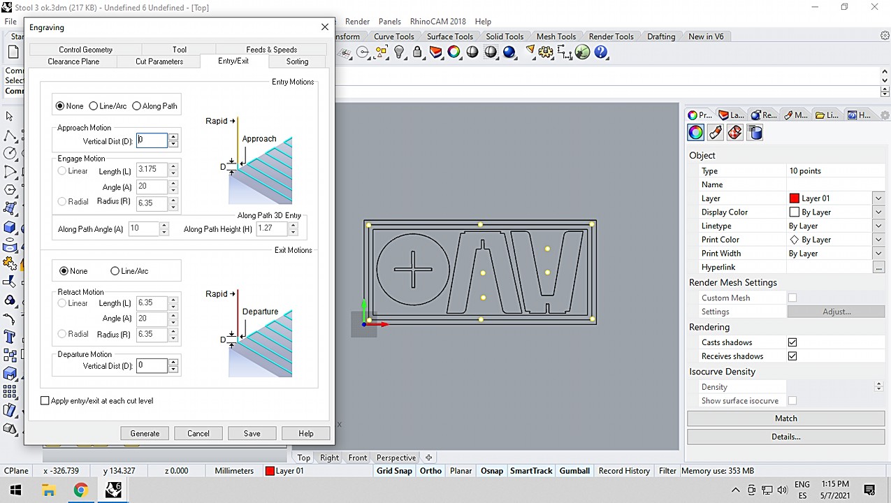
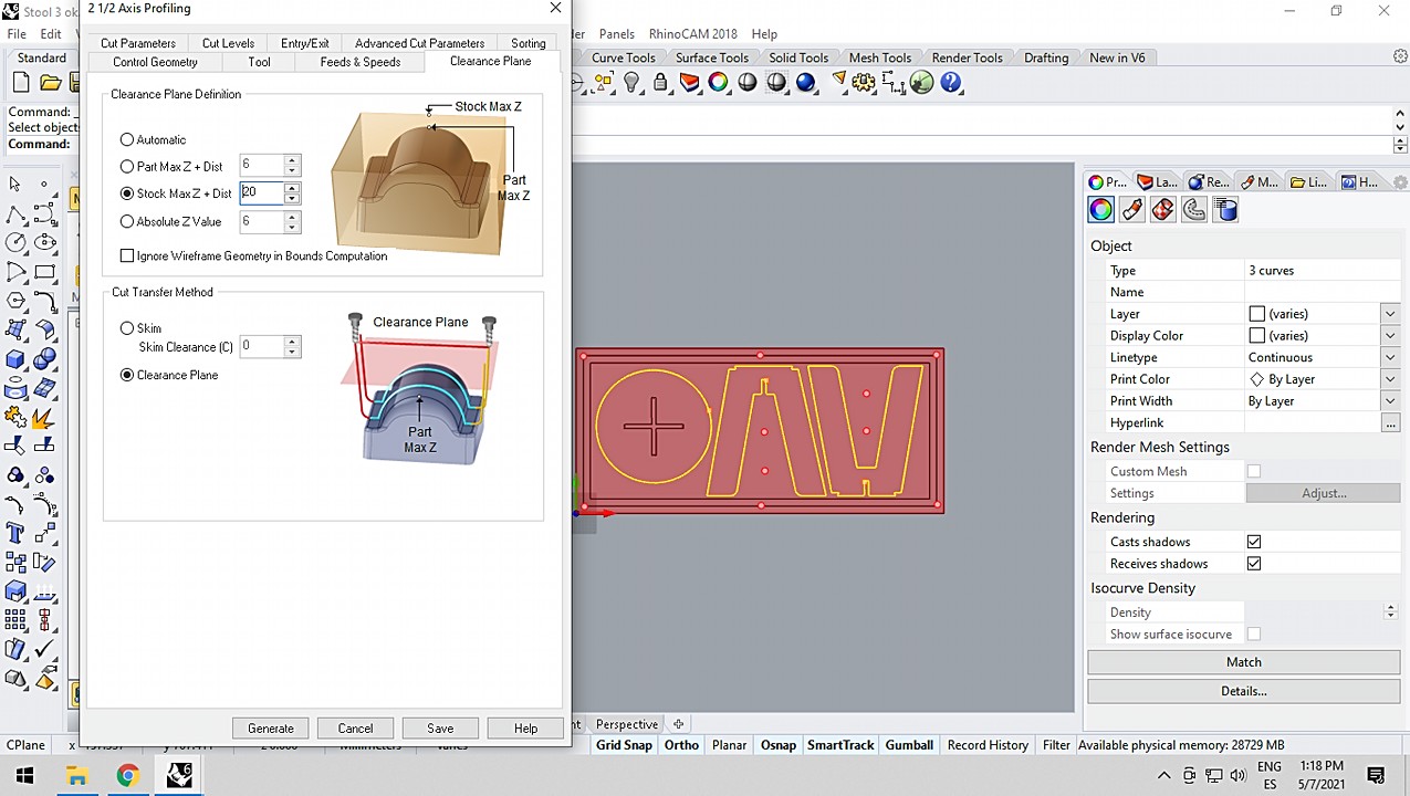
Pocketing
Since I want the upper part of the stool not to show the joint of the legs, I am going to use a pocketing that does not completely penetrate the thickness of the wood. For that and as you will see in the settings, I configure the total depth of the cut a few millimeters smaller than the wood thickness
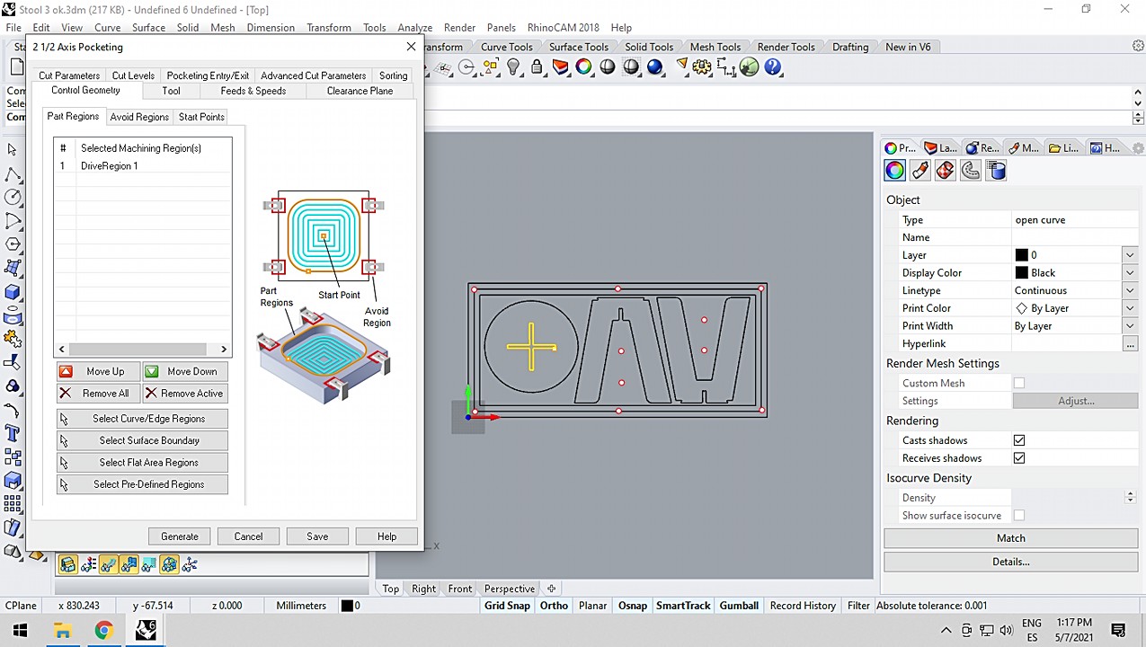

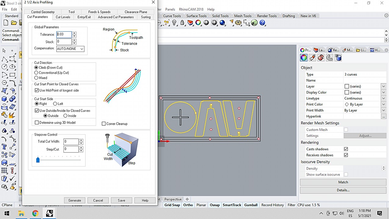
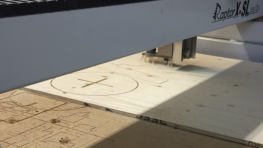
Outcut
Finally and with all the details done, we launched ourselves with the outcut: that is to say, completely cut the thickness of the wood until the pieces were released from the board. As you will see, I have left some small tabs that hold the pieces to the wood. This is a safety measure since when released from the general body, they could fly off due to the force of the spindle.
Now that I have finally finished preparing my files, it is time to cut; FINALLY!!!!! I really looked forward to this week and especially the CNC but on the big machine. I am passionate about furniture and I finally have the opportunity to use one of these. Let's go!
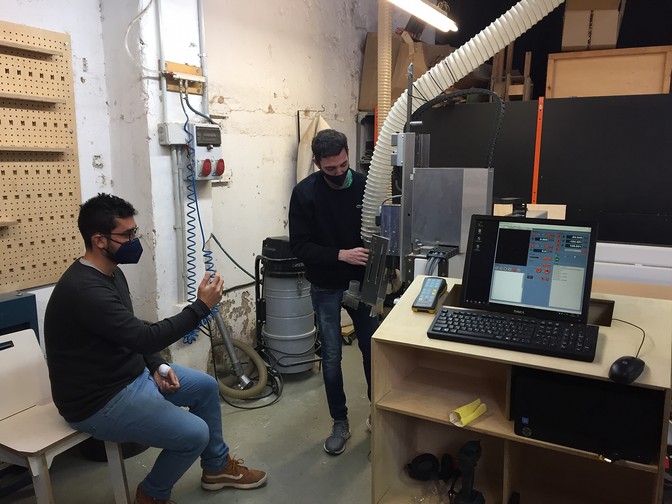
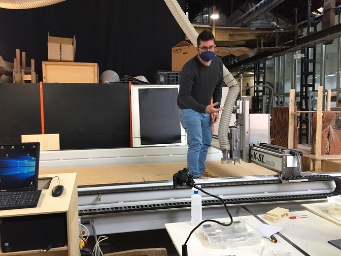
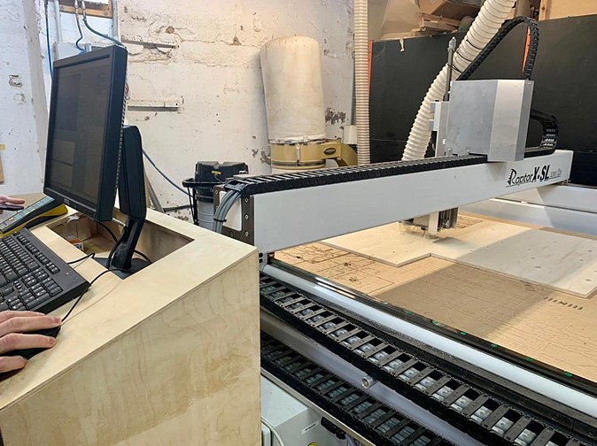
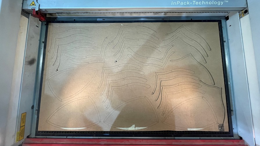
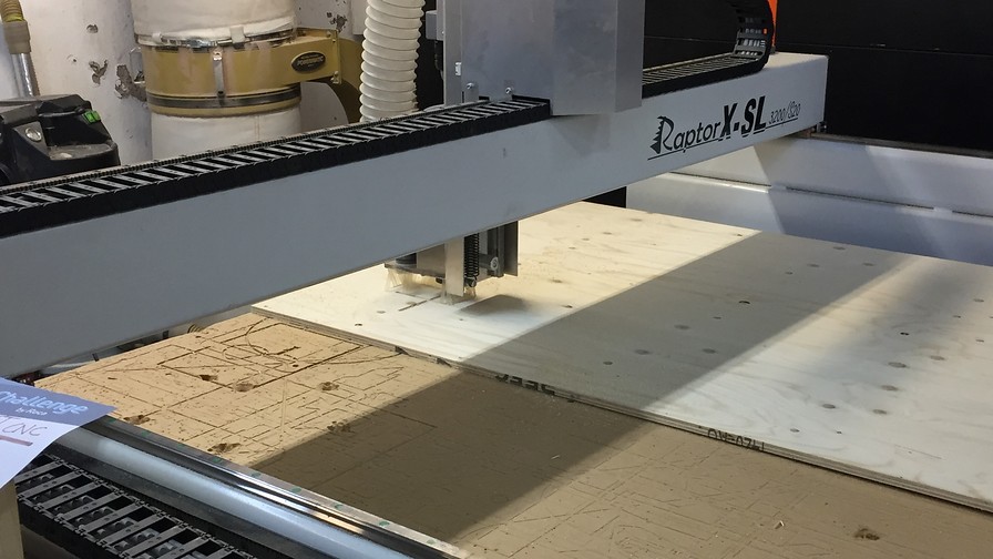
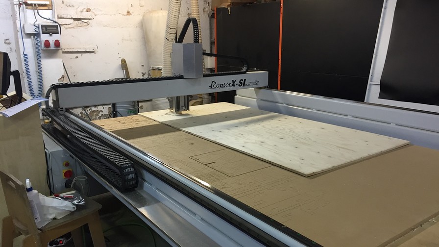
Preparations and CNC milling
The preparation is not complicated, it is only to follow the steps of how to do things safely. You basically put the board on top of the bed of the CNC and screw it tight to keep it from moving while the end mill cuts. Prepare the files on the computer and cut. For my future me, here's a little checklist of what to do for the CNC to work properly:
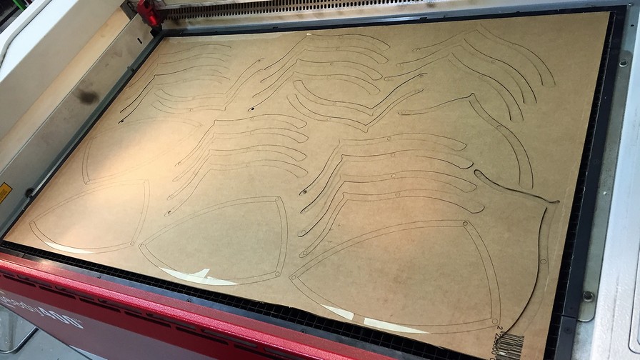
Everything went well and here are some images that I took while the machine was milling and making sure everything went well.
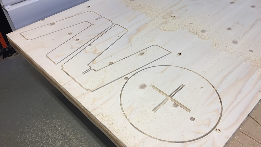
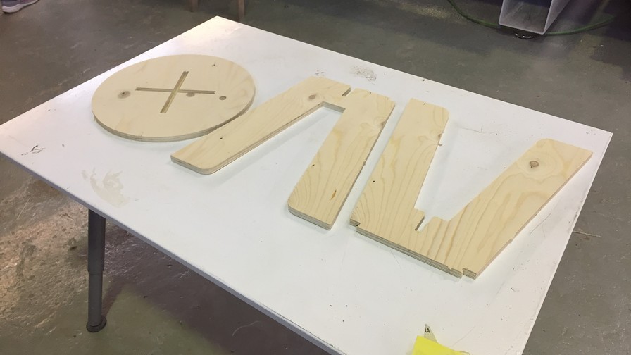
Parts before assembly
Everything went as expected and the pieces looked very good. It would be necessary to sand for a long time to clean the contours as much as possible and avoid splinters.
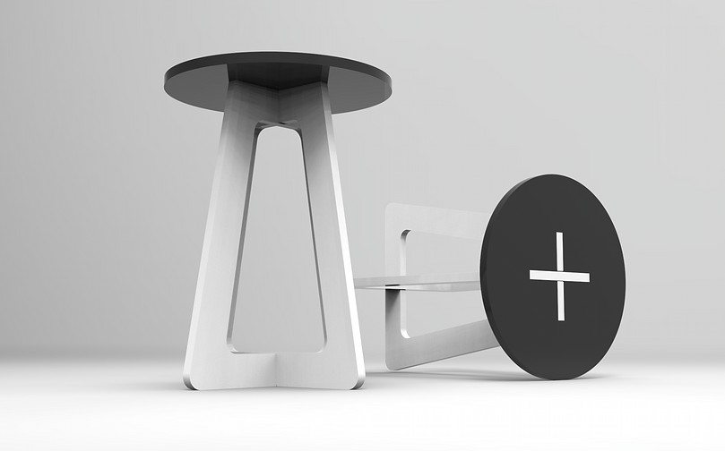
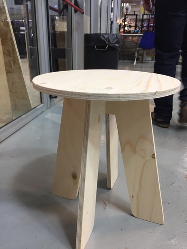
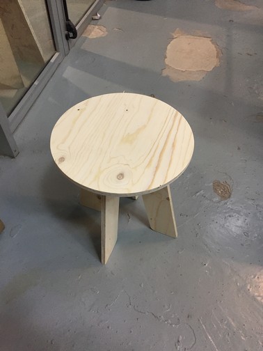
Hero Shots
Original Files
Link to Original files from this week.
What to improve for next assignments?
This week has been very frustrating, I wanted to do a great project but because of the work I had to lower my expectations. I don't want that to happen to me again.
What to keep an eye on during week 8?
· Don't let work interfere
· Get a flat at once
· Remember to work in spirals don't go crazy