Embedded Programming
EMBEDDED PROGRAMMING
This is the content we had covered this week:
W8 - Embedded Electronics
- Microcontroller Data Sheet
- Programming Microcontrollers
- Performance & Development
Assignment
-
Group assignment: Compare the performance and development workflows for other architectures
-
Individual assignment: read a microcontroller data sheet + program your board to do something, with as many different programming languages and programming environments as possible
This week we’ve been working to dig into programming electronics from very different levels. It’s quite a steep learning curve to get to a very low level programming. So better take it step by step.
HOW TO DO EMBEDDED PROGRAMMING
MICROPROCESSOR VS MICROCONTROLLER ARQUITECTURES
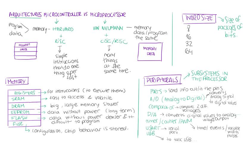
"Diagram showing architectures, memory, peripherals & word size explanations."
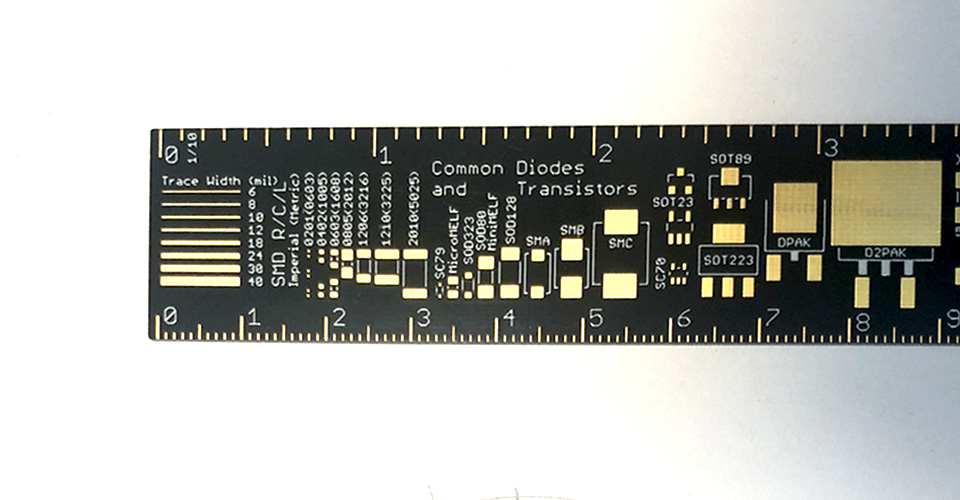
IC PACKAGES
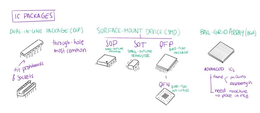
"Diagram showing IC Packages types."
GROUP ASSIGNMENT
For the group assignment we had to: compare the performance and development workflows for other architectures.
Being honest I wasn’t sure how to develop this part, so the approach I took was to tryng to make my life easier next time I need to choose a microcontroller for a specific project. I never took special attention to the Chip, so I spent some time on comparing some of the boards I had for a long time ( which some of them I haven’t even used).
THE KEY TO ALL MY PROBLEM | FIXING THE FTDI DRIVERS
I spent an unreasonable amount of time failing to program one of my boards through FTDI. The issue wasn’t the board or the programmer. It was my laptop, as I tried with another one and it worked at the first try.
Apparently I had some broken legacy FTDI drivers that didn’t work well even when updating them. So after deleting all of them and following carefully different directions from the FTDI documentation. It worked, and the USB started to recognize again the boards, YAY!
"First page of the FTDI drivers documentation."
GOING DOWN THE CHIPS RABBIT HOLE
These are all the boards I wanted to compare to share with my peers. As you can see each one has at least one different particularity.
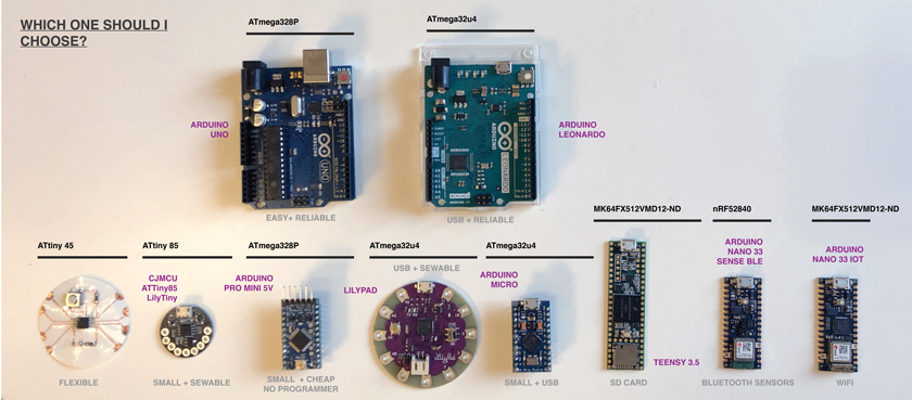
"Image showing all the different boards I analyzed."

"Image showing all the Chips' specs."
I used the Digikey’s catalog for consistency: Digikey’s catalog
THE FLEXIBLE AND THE SMALL SEWABLE ONE

"LEFT: ATTINY45 COPPER FOIL BOARD. RIGHT: CJMCU ATTiny85 LilyTiny "
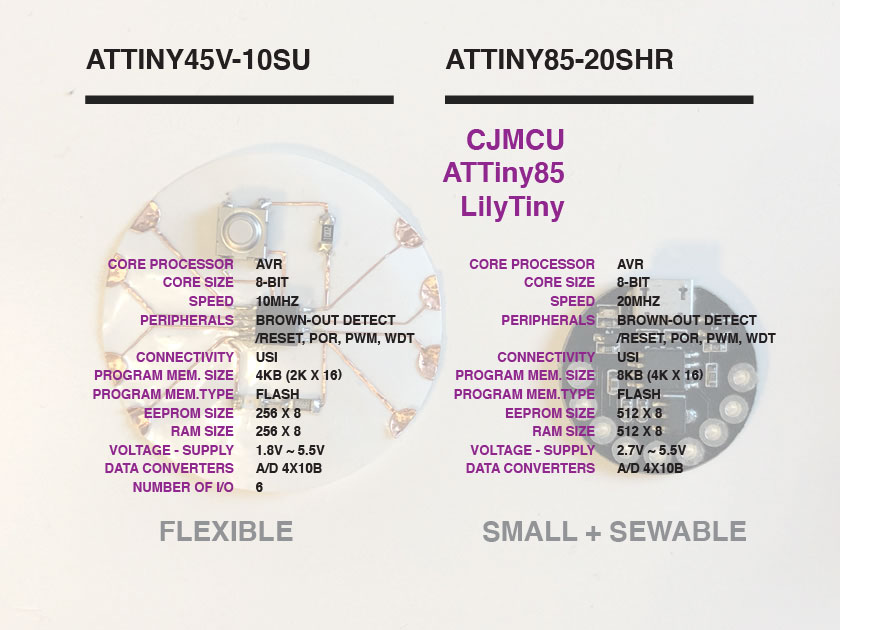
"LEFT: ATTINY45V-10SU SPECS. RIGHT: ATTINY85-20SHR SPECS "
THE SMALL AND EASY AND THE SIMPLE ONE
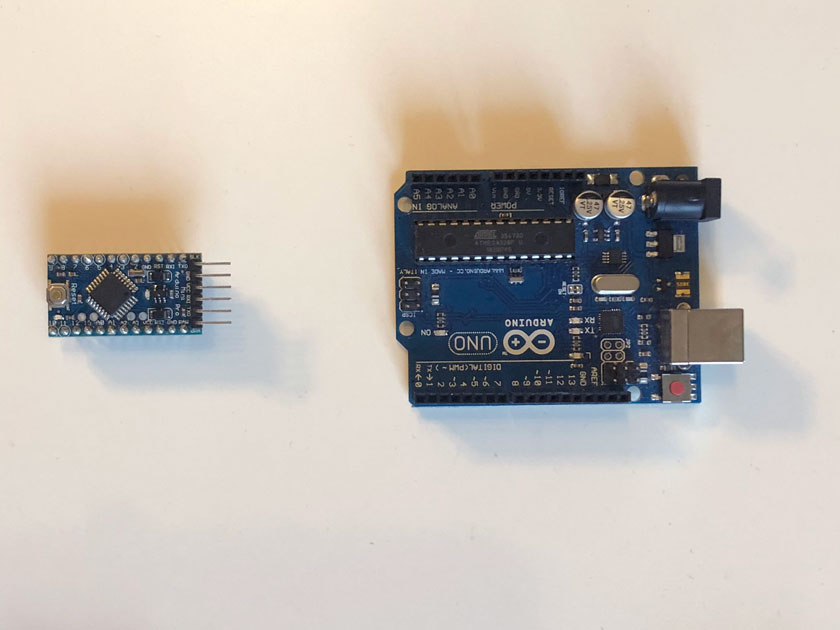
"LEFT: ARDUINO PRO MINI 5V. RIGHT: ARDUINO UNO"
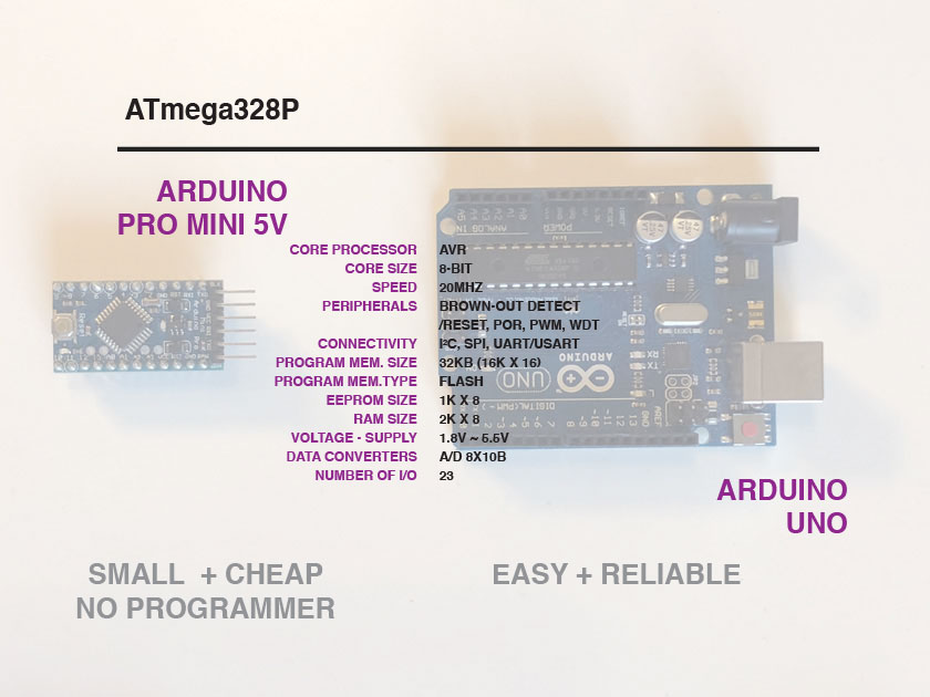
"Both ATmega328P "
THE USB HANDY, THE BIG SEWABLE ONE AND THE SMALL USB HANDY
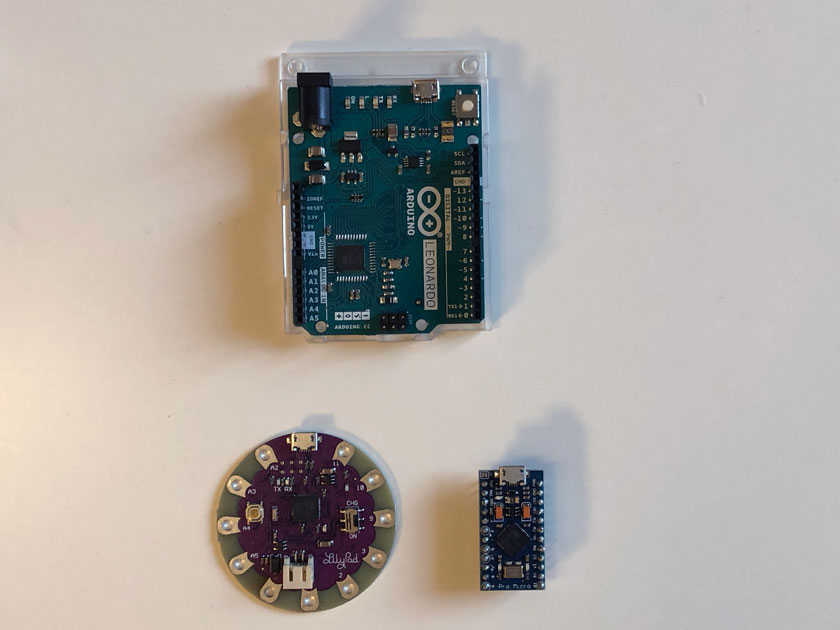
"TOP: ARDUINO LEONARDO. LEFT: LILYPAD. RIGHT: ARDUINO MICRO"
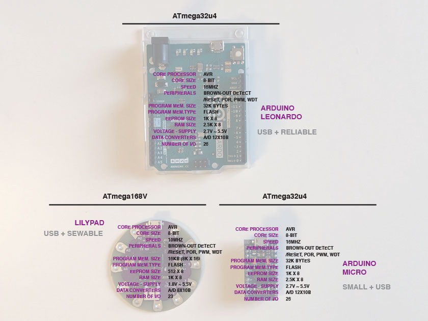
"TOP:ATmega32u4. LEFT: ATmega168V. RIGHT: ATmega32u4"
THE BIG CONNECTED FOLKS
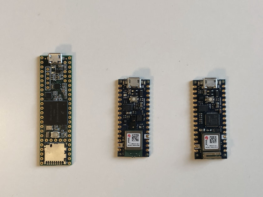
"LEFT: TEENSY 3.5. MIDDLE: ARDUINO NANO 33 SENSE BLE. RIGHT: ARDUINONANO 33 IOT"
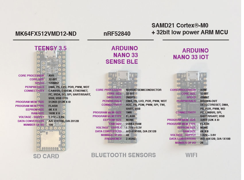
"LEFT: MK64FX512VMD12-ND. MIDDLE: nRF52840. RIGHT: SAMD21 Cortex®-M0+ 32bit low power ARM MCU"
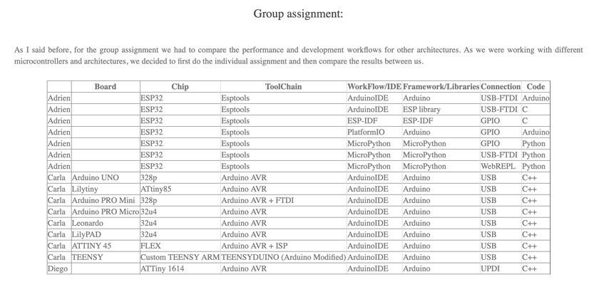
I will show later the different microcontrollers that I programmed. But as a summary of the analysis of different development workflows I created this table to showcase different parts of the process that can be often confused:
ARDUINO WORLD IS NOT JUST AN ARDUINO BOARD

"Table showing all different microcontrollers used and the different Arduino parts used & alternates."
This is a comprehensible comparison of different workflows(Including: Board type, Toolchains, libraries, IDEs, bootloaders & headers) when using commercial boards that have different chips. After discussing with my peers the boards I had at home, it seemed there was a lot of interest to see the differences between them to see the potencial our manufactured boards could have if using those chips. To me is always very helpful to see commercial solutions that have been tested to envision what I could do in the future. So we agreed on spread a bit the work to have a larger set of chips to compare instead of only the ones we have at the lab.
Other peers have checked performances & workflows, Adrien & [Diego] (http://fabacademy.org/2021/labs/barcelona/students/diego-diaz/fabacademy/week8/week8.html), including all the analysis I provided.
The set all-together is quite complete as it can be seen here.
"Screenshot from Diego's site including all the workflows we anylized as a group.".
WHAT WENT WELL
First of a kind: I’ve never looked at the boards from this deep analysis. I used to choose by features rather than specs.
More to learn: I acquired a good foundation on the microcontroller specs; so I’ll keep building on it.
WHAT COULD BE BETTER
Low-level uncomfort:I decided to stay in a higher level programming to be more comfortable trying many chips rather than one.
Larger scope: I wanted to have even a broader span of options. But, it’s quite timeconsuming….
INDIVIDUAL ASSIGNMENT
HOW TO READ A DATASHEET
I’ve skimmed before on a datasheet but never got as deep as this time. I knew I needed and strategy to succeed on this quest so this resource was extremely helpful:
Sparkfun Tutorial about How to read a datasheet
It explain the main elements that one might need to find on a datasheet:
- Summary
- Pinout
- Absolute Maximum Ratings
- Recommended Operating Conditions
- Performance graphs
- Truth tables
- Timing diagrams
- application information
- Some: example schematics
- packaging information Bonus - Errata documents
So I went with this strategy to the documentation of the ATtiny25/V
Atmel Datasheet: ATtiny25/V / ATtiny45/V / ATtiny85/V Complete Data Sheet
To be honest the summary was more enough to get what I needed this time:
Atmel Datasheet: ATtiny25/V / ATtiny45/V / ATtiny85/V Summary
The main elements I needed before programming my microcontroller are the ones that follow:
PIN CONFIGURATIONS
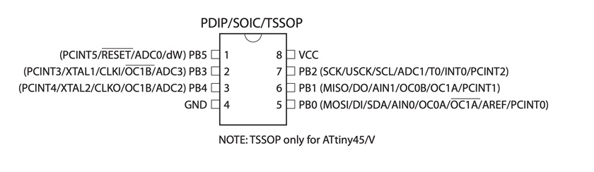
"Attiny 45V Pinout."
Documentation for Attiny 85 might work as well.
SPECS
ATtiny25V/45V/85V: 0 – 4 MHz @ 1.8 - 5.5V, 0 - 10 MHz @ 2.7 - 5.5V
PROGRAMMING ATTINY 45 USING ARDUINO ISP
I’ve used an ATTiny in the past but never an SMD one. So the challenge to program it was that the the circuit had to consider providing connection to the 6 programming pins.
In the past I’ve used the SparkFun Tiny AVR Programmer, which I couldn’t use because my microcontroller wasn’t through-hole.
PROGRAMMING CIRCUIT A | ATTINY 45 CIRCUIT BY HAND
This was a moment of truth to know if my hand-crafted board worked.
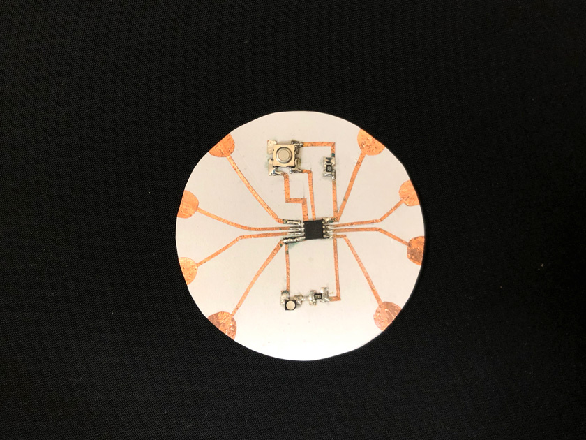
"Final Hand-made Attiny 45 circuit."
STEP 1: LOOK UP FOR DOCUMENTATION
As I’m programming an old generation Attiny, I know I need an ISP programmer. I don’t have one but I know Attiny’s can be programmed using Arduino. So after looking for Arduino ISP I found multiple handy resources:
STEP 2: CONVERT ARDUINO UNO INTO ARDUINO ISP
To use the Arduino as a programmer you need to add a large capacitor (10uF electrolytic capacitor) between ground and the reset Pin to prevent the arduino from reseting.
"LEFT: Board ready with aligator clips. RIGHT: Arduino with a 10uF capacitor between reset and GND "
Now, upload the Arduino ISP example code into the Arduino ( Make sure the Arduino UNO is using the right programmer Tools > Programmer > AVR ISP).
Once it’s done, the Arduino ISP is ready!
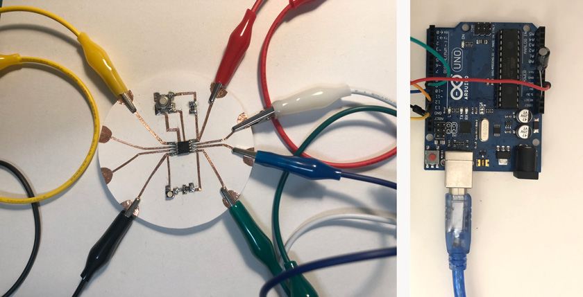
STEP 3: WIRE ARDUINO UNO + BOARD
Arduino pins as SPI pins:
- Arduino 5V connects to ATTiny45 Pin 8 (Vcc)
- Arduino GND connects to ATTiny45 Pin 4 (GND)
- Arduino Pin 13 connects to ATTiny45 Pin 7 (SCK)
- Arduino Pin 12 connects to ATTiny45 Pin 6 (MISO)
- Arduino Pin 11 connects to ATTiny45 Pin 5 (MOSI)
-
Arduino Pin 10 connects to ATTiny45 Pin 1 (Student Reset)
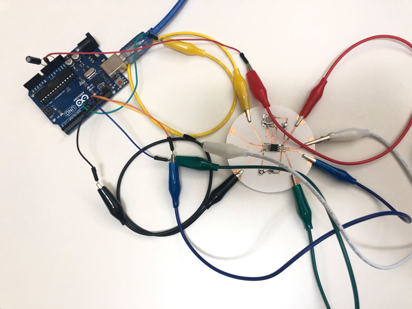
"Arduino connected to the board. Red: 5V , Black: GND, White: SCK, Blue: Miso, Green: Mosi, Yellow: Student/ Reset"
STEP 4: INSTALLING BOARD MANAGER
Installation instructions for Attiny Core
STEP 5: SELECT PROGRAMMER
After installing Attiny board select Arduino ISP as a programmer. This will allow programming the Attiny by using the Arduino as the ISP programmer.
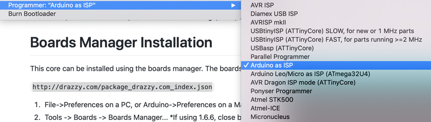
"Select Arduino ISP as programmer"
STEP 6: SELECT MICROCONTROLLER
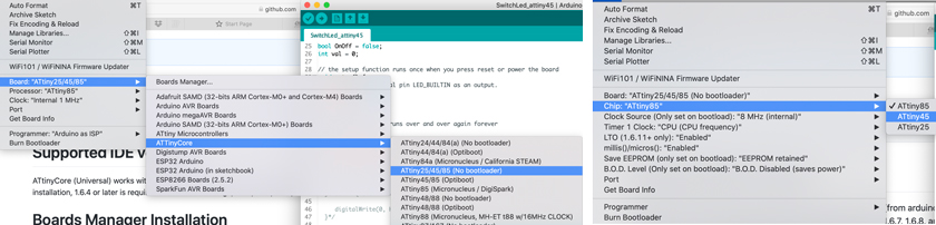
"RIGHT: Select ATtiny 25/45/85 ( No bootloader) LEFT: Select Attiny 45 as a microcontroller."
STEP 7: BURN BOOTLOADER
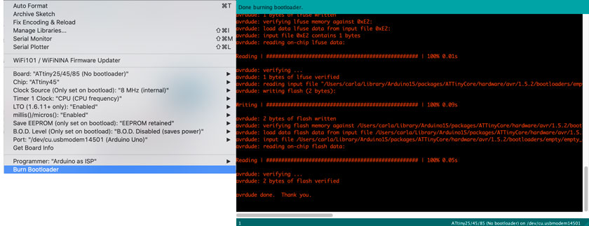
"RIGHT: Burn Bootloader LEFT: Done burning bootloader message."
STEP 8: UPLOAD CODE USING THE ARDUINO AS PROGRAMMER
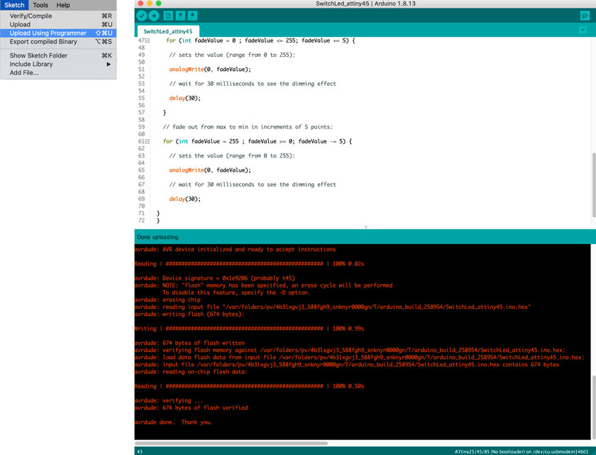
"LEFT: Upload code using Sketch --> Upload Using programmer. RIGHT: Arduino IDE showing code + verbose console with successful upload."
STEP 9: TEST BOARD
I decided to test the board incrementally. Every time I added a feature, I recorded a video.
- Blinking LED
Download ATtiny 45 Blinking LED code
/*
  Blink

  Turns an LED on for one second, then off for one second, repeatedly.

  Most Arduinos have an on-board LED you can control. On the UNO, MEGA and ZERO
  it is attached to digital pin 13, on MKR1000 on pin 6. LED_BUILTIN is set to
  the correct LED pin independent of which board is used.
  If you want to know what pin the on-board LED is connected to on your Arduino
  model, check the Technical Specs of your board at:
  https://www.arduino.cc/en/Main/Products

  modified 8 May 2014
  by Scott Fitzgerald
  modified 2 Sep 2016
  by Arturo Guadalupi
  modified 8 Sep 2016
  by Colby Newman

  This example code is in the public domain.

  http://www.arduino.cc/en/Tutorial/Blink
*/

// the setup function runs once when you press reset or power the board
void setup() {
  // initialize digital pin LED_BUILTIN as an output.
  pinMode(0, OUTPUT);
}

// the loop function runs over and over again forever
void loop() {
  digitalWrite(0, HIGH);   // turn the LED on (HIGH is the voltage level)
  delay(1000);                       // wait for a second
  digitalWrite(0 , LOW);    // turn the LED off by making the voltage LOW
  delay(1000);                       // wait for a second
}
- Blinking LED + 3V battery
- Button turning on LED
In this case the Led is connected to ATtiny’s pin 5 which is PWM and allows the LED to dim.
- Button + Dimming Led
Download ATtiny 45 Blinking LED code
/*
  Blink

  Turns an LED on for one second, then off for one second, repeatedly.

  Most Arduinos have an on-board LED you can control. On the UNO, MEGA and ZERO
  it is attached to digital pin 13, on MKR1000 on pin 6. LED_BUILTIN is set to
  the correct LED pin independent of which board is used.
  If you want to know what pin the on-board LED is connected to on your Arduino
  model, check the Technical Specs of your board at:
  https://www.arduino.cc/en/Main/Products

  modified 8 May 2014
  by Scott Fitzgerald
  modified 2 Sep 2016
  by Arturo Guadalupi
  modified 8 Sep 2016
  by Colby Newman

  This example code is in the public domain.

  http://www.arduino.cc/en/Tutorial/Blink
*/

bool OnOff = false;
int val = 0;

// the setup function runs once when you press reset or power the board
void setup() {
  // initialize digital pin LED_BUILTIN as an output.
  pinMode(0, OUTPUT);
  pinMode(2, INPUT);
}

// the loop function runs over and over again forever
void loop() {

  val = digitalRead(2);   // read the input pin
  //digitalWrite(0, val);

 if (val == HIGH){
  digitalWrite(0 , LOW);    // turn the LED off by making the voltage LOW

  }else if ( val ==LOW){


     for (int fadeValue = 0 ; fadeValue <= 255; fadeValue += 5) {

      // sets the value (range from 0 to 255):

      analogWrite(0, fadeValue);

      // wait for 30 milliseconds to see the dimming effect

      delay(30);

    }

    // fade out from max to min in increments of 5 points:

    for (int fadeValue = 255 ; fadeValue >= 0; fadeValue -= 5) {

      // sets the value (range from 0 to 255):

      analogWrite(0, fadeValue);

      // wait for 30 milliseconds to see the dimming effect

      delay(30);

  }
  }


}
STEP 10: “STANDALONE” BOARD
- Button + Dimming Led + Battery
HERO SHOT: PROGRAMMING CIRCUIT A | ATTINY 45 CIRCUIT BY HAND
PROGRAMMING CIRCUIT B | ATTINY 45 CIRCUIT COPPER FOIL LASER
The process to program this board was exactly the same as its hand-made predecessor.
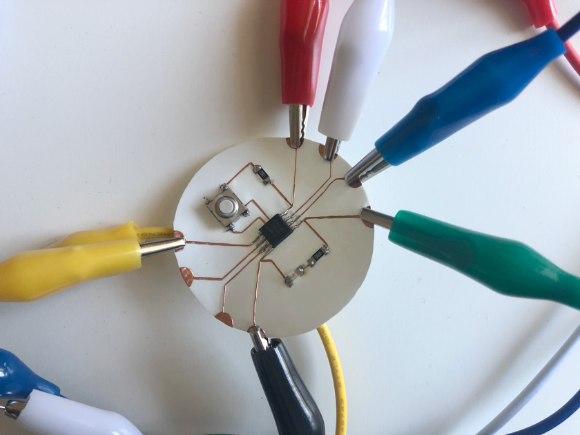
"Image showing ATTINY 45 board with aligator clips."
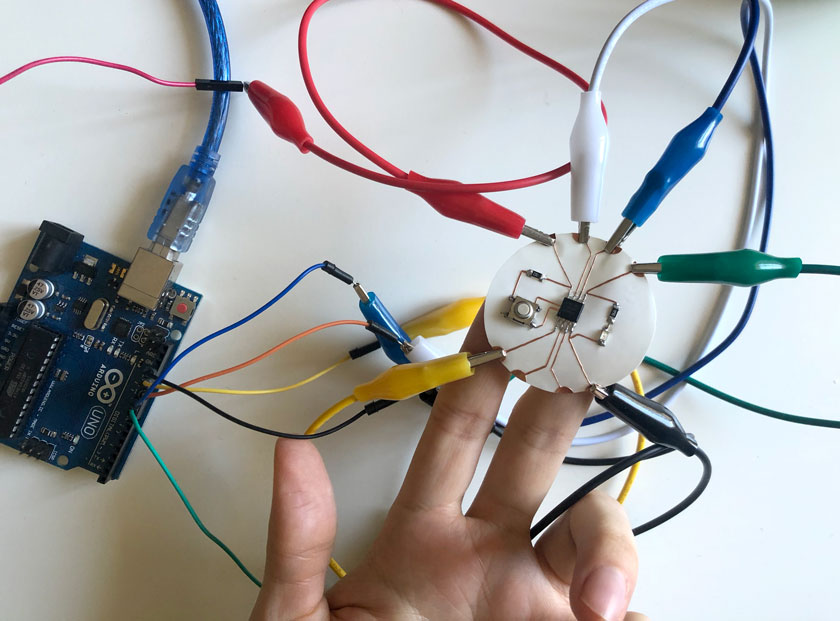
"Image showing ATTINY 45 board with aligator clips connected to the Arduino (as Arduinoi ISP) ready to be programmed.
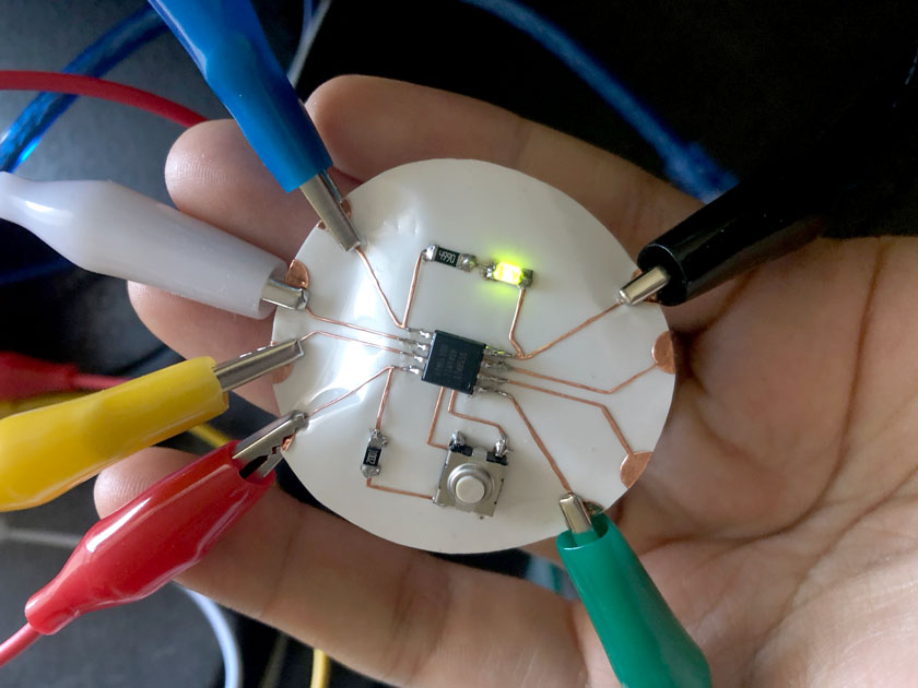
"Image showing ATTINY 45 with dimming LED.
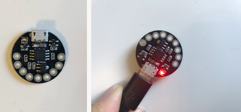
PROGRAMMING ATTINY 85 WITH DIGISTAMP TOOLCHAIN + MICRONUCLEUS (bootloader)
This board was one of the boards I could use after fixing my FTDI drivers as before it wasn’t even recognized.
Programming CJMCU guide Retailers page
Despite ATtiny 85 doesn’t have USB support, with this one I used MicroNucleus for the first time to be able to program it directly with a USB connection instead of using an ISP. Micronucleus is considered the smallest USB bootloader for AVR ATtiny.
https://github.com/micronucleus/micronucleus
ADD BOARD LIBRAY
-
We need to add this board library url Library link
-
from the board manager, Install –> Digistump AVR Boards
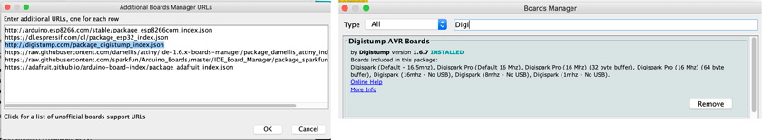
"LEFT: Adding Board Library url. RIGHT: Installing Boards inside Arduino IDE's Board manager."
Fix the Avr-gcc compiler
The following commands replace the avr-gcc compiler that comes with the board manager libraries with the embedded into Arduino IDE, which has everything you need to program this board.
Close arduino IDE; open a terminal run the following commands:
cd ~/Library/Arduino15/packages/arduino/tools/avr-gcc
mv 4.8.1-arduino5 orig.4.8.1
ln -s /Applications/Arduino.app/Contents/Java/hardware/tools/avr 4.8.1-arduino5
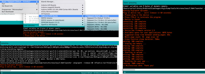
PROGRAMMING BOARD
"LEFT: CJMCU ATtiny85 Lilytiny. RIGHT: Blinking Lilytiny ."
"First page of the FTDI drivers documentation."
Download LilyTiny Blinking LED code
PROGRAMMING ARDUINO PRO MINI USING FTDI AS PROGRAMMER
I wanted to try the FTDI board we did during week 4. As my board didn’t use UPDI I didn’t need to use it this week. So I tried to program an Arduino Pro Mini that doesn’t have USB.
As there are two types of Arduino Pro Mini - 5V & 3.3V, I wanted to check the documentation. This one from Sparkfun was great:
Arduino Pro Mini Documentation
FIXING THE FTDI AND TESTING A COMMERCIAL SOLUTION
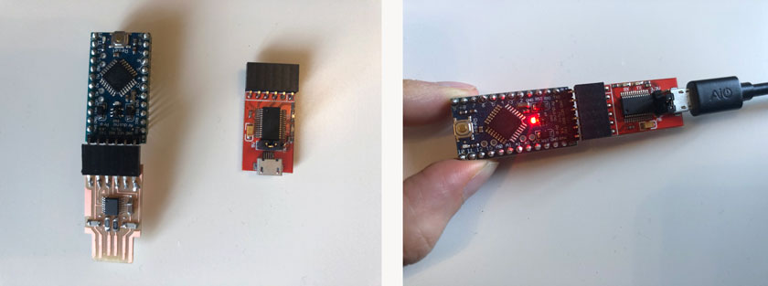
"LEFT: Arduino Pro Mini + FabAcademy FTDI board + Commercial FTDI. RIGHT: Commerical FTDI used to programm a Blink on the Pro mini."
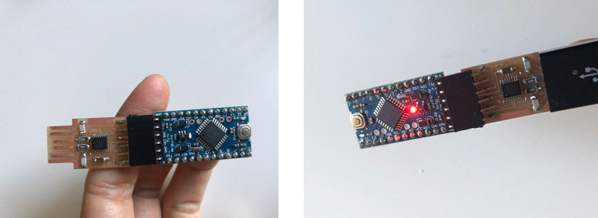
"LEFT: Testing Fabacademy's FTDI board. RIGHT: Non blinking board, power works."
FABACADEMY FTDI DOESN’T WORK TO PROGRAM THE ARDUINO PRO MINI :(

"LEFT UP: Usb being detected using FabAcademy's FTDI. LEFT DOWN: Realising that the reset trace is not part of this design. RIGHT: AVR dude problems, the board could not be programmed."
I believe the FabAcademy FTDI doesn’t have the reset trace as it’s not needed to program using UPDI ( only needs TX and RX). The Arduino Pro Mini needs the Reset of the FTDI to be used as a programmer.
PROGRAMMING ARDUINO PRO MICRO USING USB
The Arduino Pro Micro was very straightforward as it was the last I tried after fixing the FTDI drivers. The fun fact is that this board was labeled as not working since two years ago when my FTDI started failing. I happy to see it’s back to life.
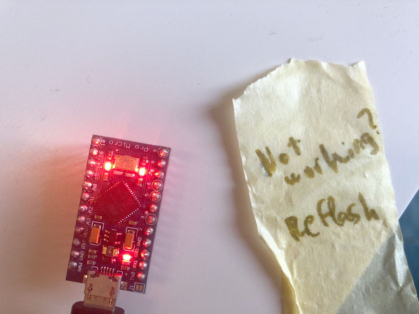
"Arduino Pro Micro back to life."
Download Arduino Pro Micro Blinking LED code
PROGRAMMING TEENSY 3.5 USING TEENSYDUINO
My last step here is to test programming the Teensy 3.5. The Teensy has it’s own arduino IDE integration –> Teensyduino which makes the experience interesting.
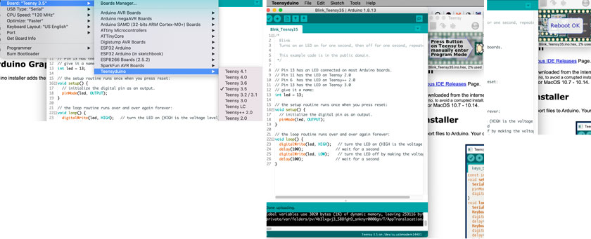
"RIGHT:Teensyduino Boards, choose 3.5. Middle: Teensyduino blink sketch + floating window with instructions. LEFT: Boot floating window."
Download Teensy 3.5 Blinking LED code
ARDUINO WORLD IS NOT JUST AN ARDUINO BOARD
"Table showing all different microcontrollers used and the different Arduino parts used & alternates."
WHAT WENT WELL
Went a bit out of my comfort zone: I stayed withing the Arduino world but mixing up some Toolchains and libraries, to make sure I understood everything properly.
A lot: I’m happy to have more comprehension of the different elements that make everything happen.
WHAT COULD BE BETTER
Could have been even further away of my comfort zone:I could have used more low-level programming to program my boards.
Less overwhelming process: There was a lot of documentation involved, both read and produced. That’s quite overwhelming.
BONUS TRACK | PROGRAMMING ATTINY WITH C A SIMPLE BLINK
This part was the most challenging of this week’s assignment for sure. I had to review Josep’s lecture from Networking week to get a reminder of some fundamentals. Check from 2:04:38 where he talks about Port registers
Even though I’m not using the UNO( ATMega 328P), this Port registers page is helpful as well!
Check this tutorial, super handy! After reading this article I was able to transform a functional blink Arduino code into C.
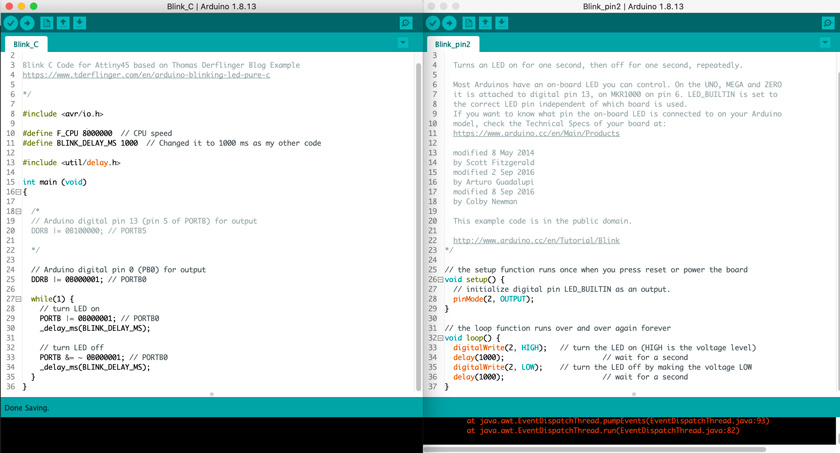
"LEFT: Arduino IDE using C to blink an LED. RIGHT: Arduino code used as a reference to code with C using the same structure.
/*

Blink C Code for Attiny45 based on Thomas Derflinger Blog Example
https://www.tderflinger.com/en/arduino-blinking-led-pure-c

*/

#include <avr/io.h>

#define F_CPU 8000000  // CPU speed
#define BLINK_DELAY_MS 1000  // Changed it to 1000 ms as my other code

#include <util/delay.h>

int main (void)
{

  /*
  // Arduino digital pin 13 (pin 5 of PORTB) for output
  DDRB |= 0B100000; // PORTB5

  */

  // Arduino digital pin 0 (PB0) for output
  DDRB |= 0B000001; // PORTB0

  while(1) {
    // turn LED on
    PORTB |= 0B000001; // PORTB0
    _delay_ms(BLINK_DELAY_MS);

    // turn LED off
    PORTB &= ~ 0B000001; // PORTB0
    _delay_ms(BLINK_DELAY_MS);
  }
}
I used the hand made attiny 45 board instead of the vinyl cut one because it got damaged after weeks 10 intense manipulation. I’m thrilled to see this low-tech baby still works!
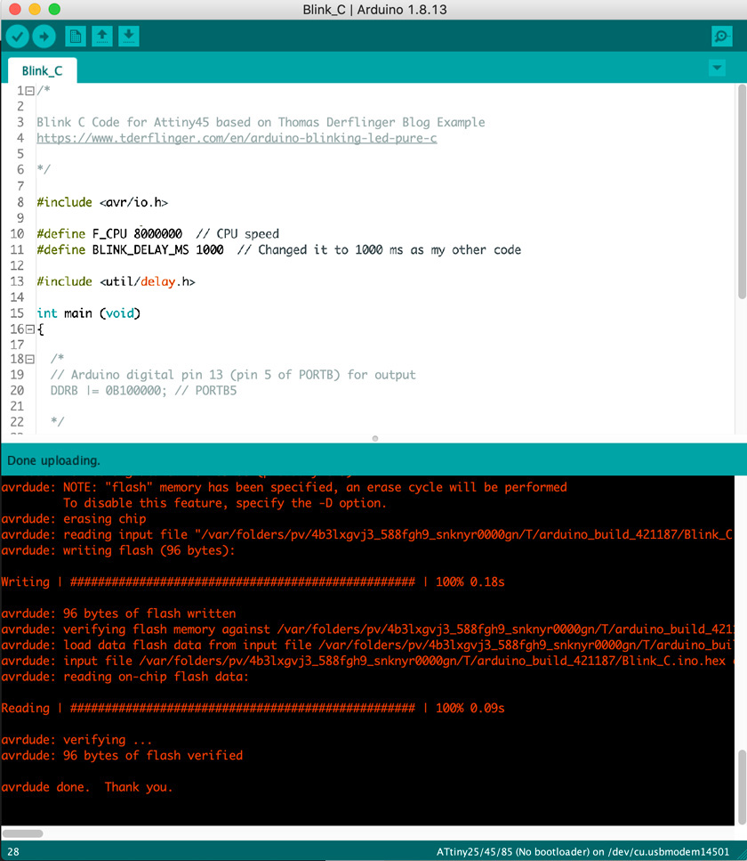
"Yay! The code uploaded well Using Arduino ISP as a programmer".
I’ve used exactly the same steps to upload the C code than I did with the Arduino one. So you can go above these page and do the same steps.
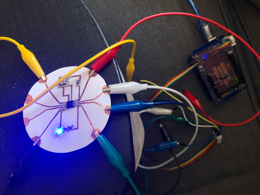
"My beloved ISP programmer + aligator clips bundle of wires while blinking the LED".
HERO C SHOT
"Cutting final pieces with the CNC"