WEEK 8: Embeded programing
This week was about programming microcontrollers. As other weeks there were a group assignment and an individual assignment.
For the individual asignment the task was to read a microcontroller data sheet and to program our board to do something. For the group assignment we had to compare the performance and development workflows for other architectures.
Group assignment:
As I said before, for the group assignment we had to compare the performance and development workflows for other architectures. As we were working with different microcontrollers and architectures, we decided to first do the individual assignment and then compare the results between us.
| Board | Chip | ToolChain | WorkFlow/IDE | Framework/Libraries | Connection | Code | |
|---|---|---|---|---|---|---|---|
| Adrien | ESP32 | Esptools | ArduinoIDE | Arduino | USB-FTDI | Arduino | |
| Adrien | ESP32 | Esptools | ArduinoIDE | ESP library | USB-FTDI | C | |
| Adrien | ESP32 | Esptools | ESP-IDF | ESP-IDF | GPIO | C | |
| Adrien | ESP32 | Esptools | PlatformIO | Arduino | GPIO | Arduino | |
| Adrien | ESP32 | Esptools | MicroPython | MicroPython | GPIO | Python | |
| Adrien | ESP32 | Esptools | MicroPython | MicroPython | USB-FTDI | Python | |
| Adrien | ESP32 | Esptools | MicroPython | MicroPython | WebREPL | Python | |
| Carla | Arduino UNO | 328p | Arduino AVR | ArduinoIDE | Arduino | USB | C++ |
| Carla | Lilytiny | ATtiny85 | Arduino AVR | ArduinoIDE | Arduino | USB | C++ |
| Carla | Arduino PRO Mini | 328p | Arduino AVR + FTDI | ArduinoIDE | Arduino | USB | C++ |
| Carla | Arduino PRO Micro | 32u4 | Arduino AVR | ArduinoIDE | Arduino | USB | C++ |
| Carla | Leonardo | 32u4 | Arduino AVR | ArduinoIDE | Arduino | USB | C++ |
| Carla | LilyPAD | 32u4 | Arduino AVR | ArduinoIDE | Arduino | USB | C++ |
| Carla | ATTINY 45 | FLEX | Arduino AVR + ISP | ArduinoIDE | Arduino | USB | C++ |
| Carla | TEENSY | Custom TEENSY ARM | TEENSYDUINO (Arduino Modified) | ArduinoIDE | Arduino | USB | C++ |
| Diego | ATTiny 1614 | Arduino AVR | ArduinoIDE | Arduino | UPDI | C++ |
Then we were able to compare the operation of the different microcontrollers and architectures, allowing us to better understand how they work.
I'm linking my classmates assignments where you can see their work with their microcontrollers:
Individual assignment
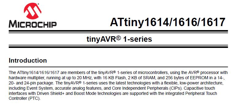
For the individual assignment I started by reading and trying to understand my microcontroller data sheet, a ATTiny1614.
Reading a microcontroller data sheet:
The tinyAVR microcontrollers are 8-bit MCUs with the following key attributes:
- Internal 20 MHz oscillator
- Up to 32 KB of Flash memory
- Up to 2 10-bit ADCs
- Peripheral Touch Controller (PTC)
- Cyclic Redundancy Check (CRC) scan
- 16-bit real-time clock and periodic interrupt timer
- Configurable Custom Logic (CCL) peripheral
- Up to 6-channel peripheral event system
- Analog comparator with scalable reference input
- Configurable, internally generated reference voltage
- USART/SPI/dual-mode TWI
- 1.8V - 5.5V operating voltage range
- -40º to 125ºC operating temperature range
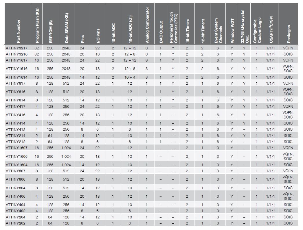
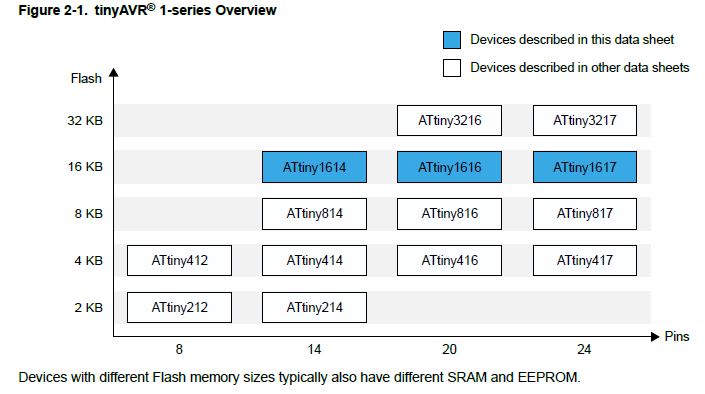
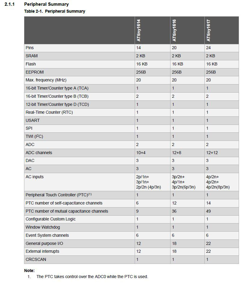
There are different microcontrollers with different Flash size, pins or RAM. In the following table and graphic are the different MCUs available on this family:
About the ATTiny1614 specifically:
The microcontroller is a 14-pin SOIC with 12 digital pins, one VCC, one GROUND, 4 PB pins and 8 PA pins. It has a UPDI/RESET pin (PA0) in order to program it via UPDI and then also a TxD (PB2) and RxD (PB3).
Scheme of the pinout:
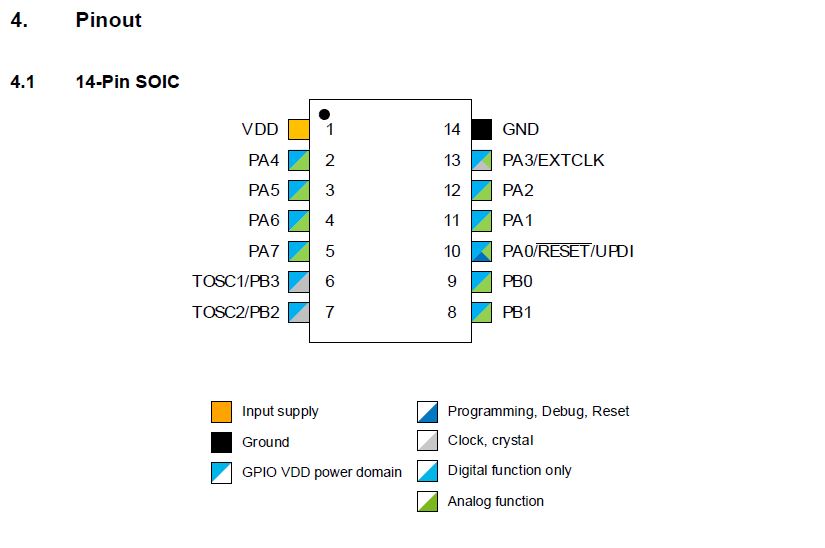
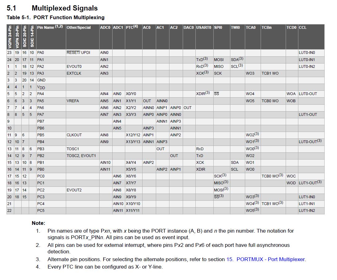
Table with the functions of all the ports:
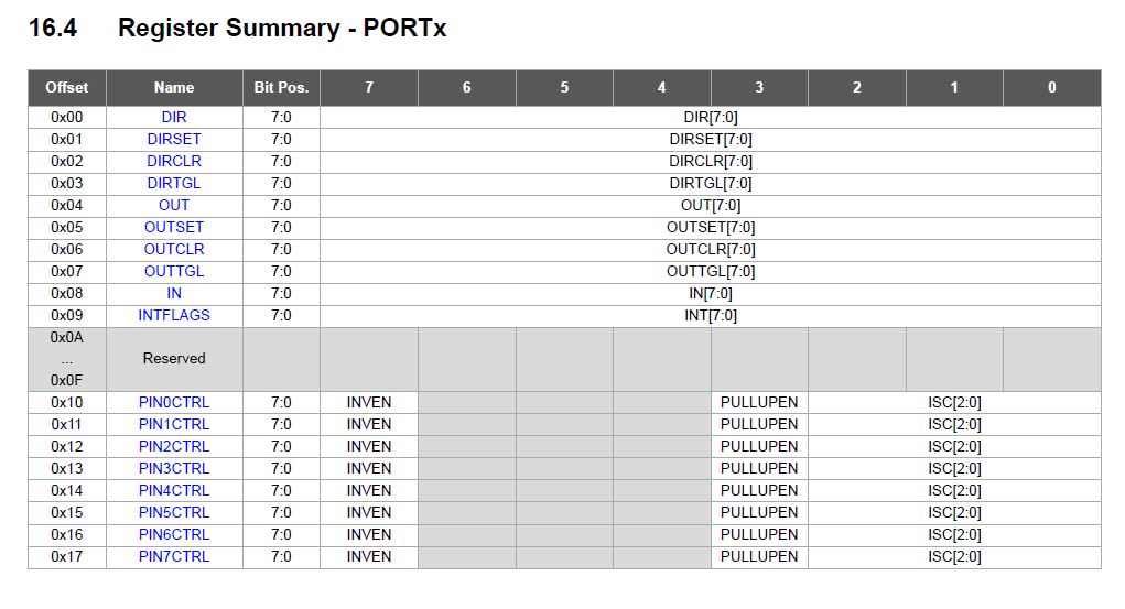
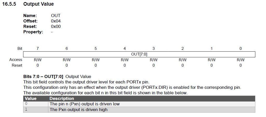
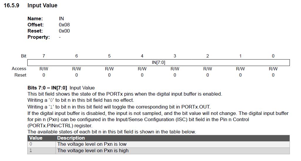
For adressing registers, I also looked at the Register Summary and Register Description parts, where you can see different programming commands that you can use and what is the parameter you change with each one.
This is the register summary with all the commands:
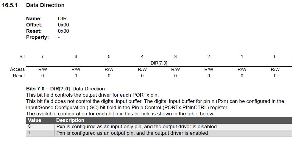
And these are the ones I used to configure my microcontroller in Arduino IDE:
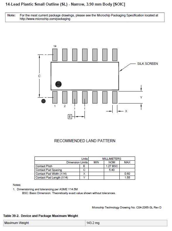
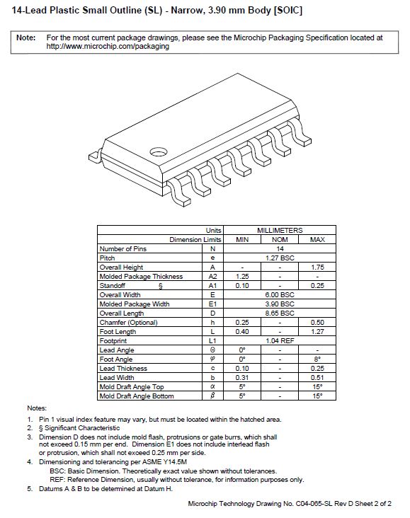
The datasheet also provides all the dimensions, of the microcontroller and its footprint in order to design our boards
Programming my ATTiny1614 board:
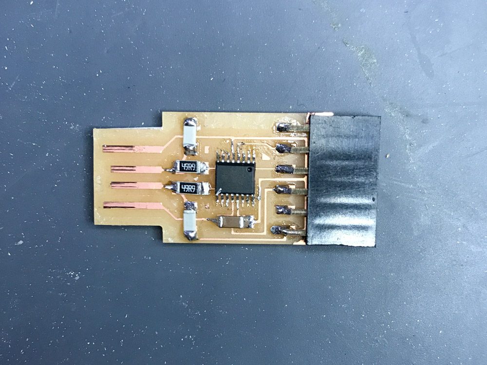
I'm using the board I made in the electronics design week, wich has a button and two leds
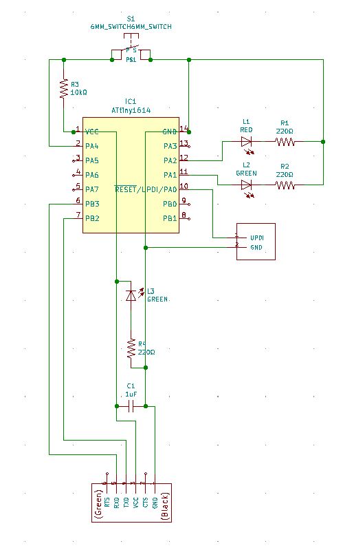
I noticed this week that the TxD and RxD pins of my microcontroller are wrong connected and I need to interchange them with each other.
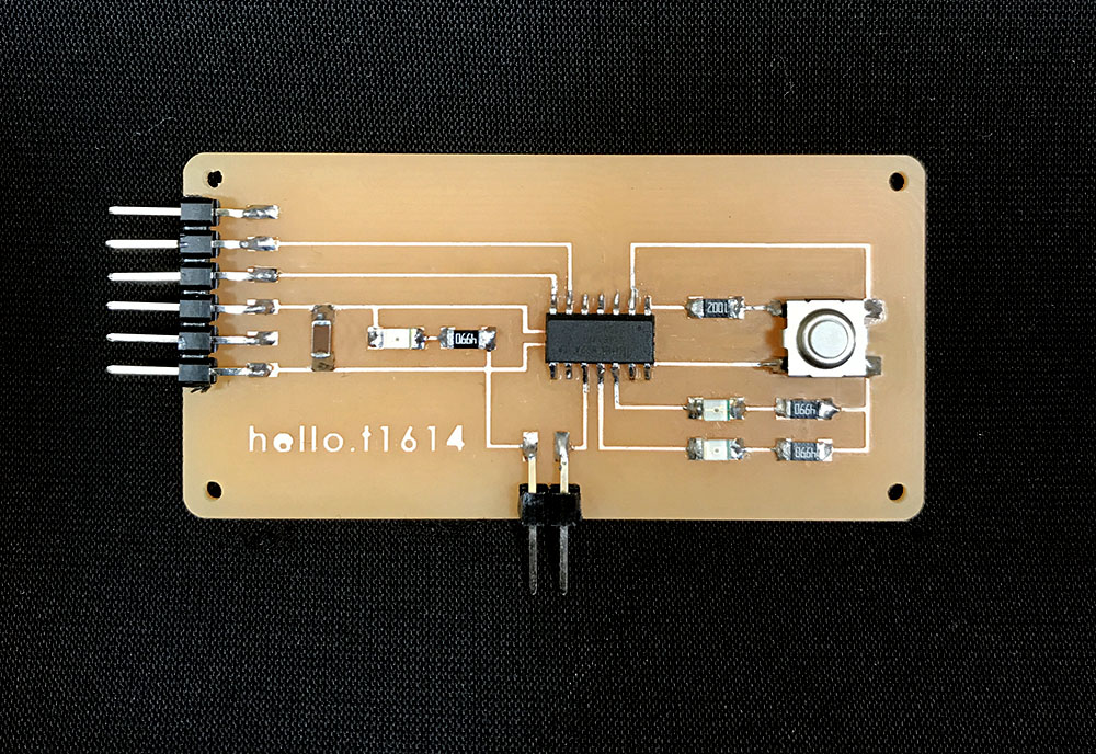
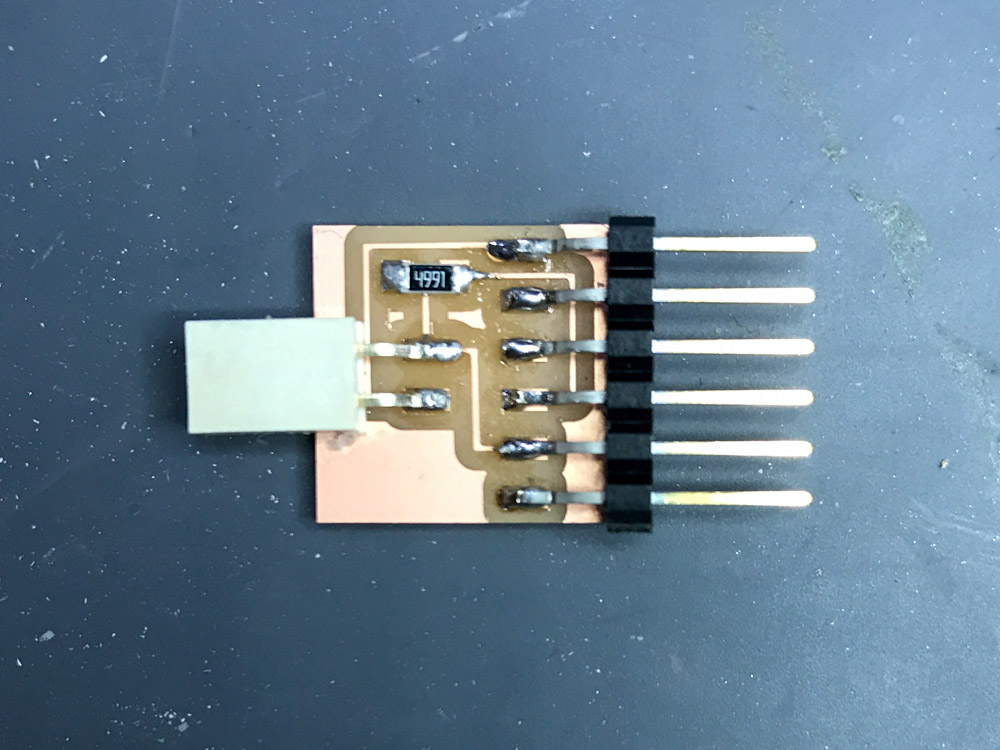
To program my board, I used the UPDI (+FTDI) programmer I made in the electronics production week.
I started using Arduino IDE, because I've been told that is the easiest way to do it.
After installing it, the first step is to download the libraries for the microcontroller. This you can do it from by copy paste this http://drazzy.com/package_drazzy.com_index.json into Arduino - File > Preferences > Aditional Boards Manager URLS. Then I went to Tools > Board manager and chose the megaTinyCore and install it.
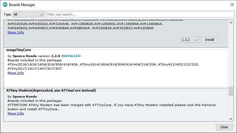
After that I chose my microcontroller in the list and left all the parameters are they were.
Once the microcontroller is conected via UPDI and it has power, everything is setted up to send the program. In my case, as my UPDI has no VCC, I had to give voltage via the FTDI conection, what I did with some different sources, like as FTDI cable, an Arduino, or a 5v battery.
The first test was programming a blink in both of the two leds my board has.
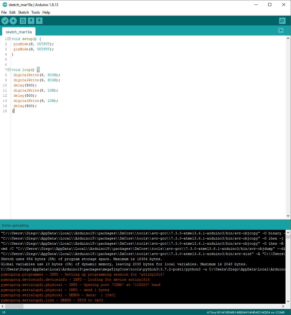
And it worked:
Then I tried with the button:
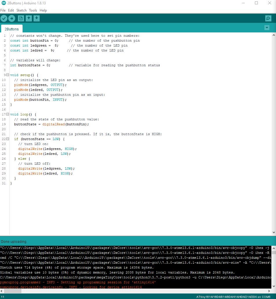
And it also worked:
After going home for weekend, Arduino IDE was giving me an error on Monday when I was trying to program my board again:
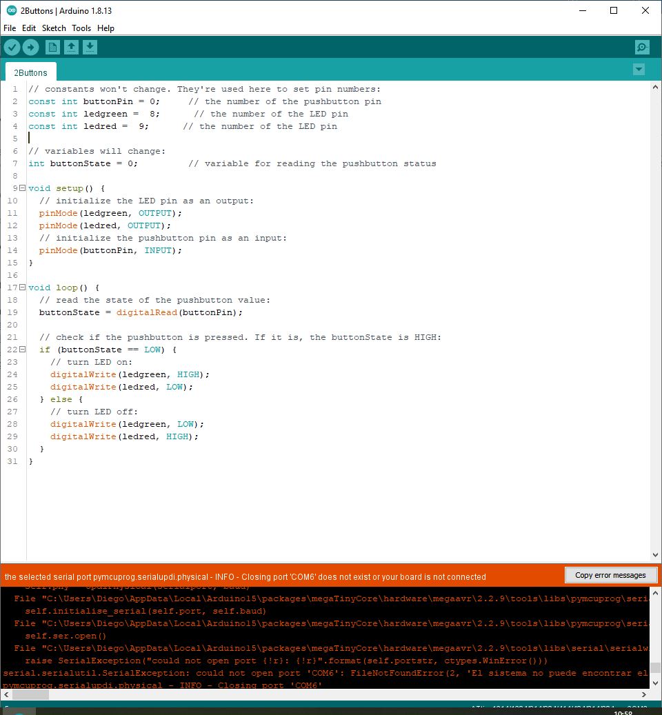
So the debugging process started. First I tried with different UPDI and FTDI boards and cables. Then I ensured that the port of my computer was correct and it was working. I also tried to give voltage from different sources. Finally, after nothing was working, I tried to resolder the board and the UPDI and FTDI boards as well just in case. It turned out well and it worked again. My guess is that the capacitor of my board was not well soldered.
Then, in order to program the same in different ways, I tried with addressing registers, with the following comands:
- PORTx.DIR register: Configures pins as input or output Do we want the pin for a button or an led? (1=OUTPUT and 0=INPUT)
- PORTx.IN register: Read data from pins Is the button pressed or not? (1=HIGH and 0=LOW)
- PORTx.OUT register: Write data to pins Turn on or off the led. (1=HIGH and 0=LOW, on INPUT pins 1=PULLUP)
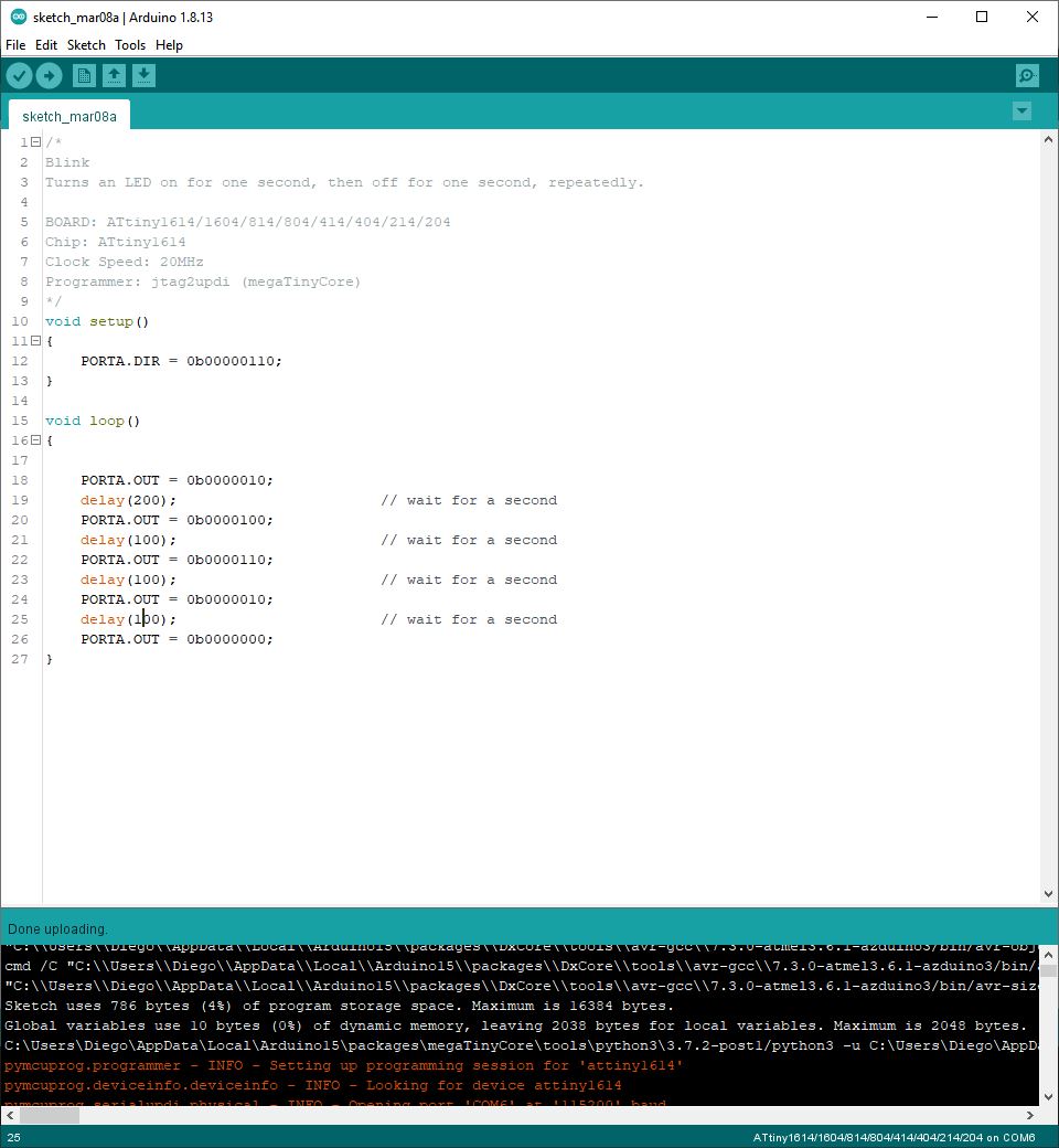
First I tested the blink:
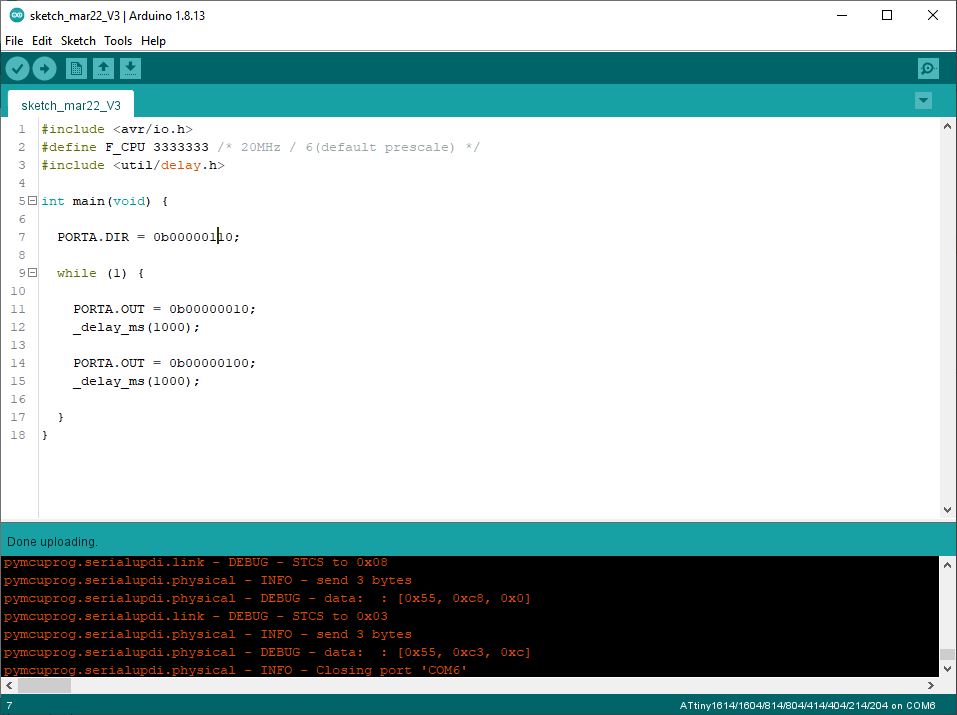
Also with plain AVR C (this is an example taken from FabLabBCN fabacademy classes):
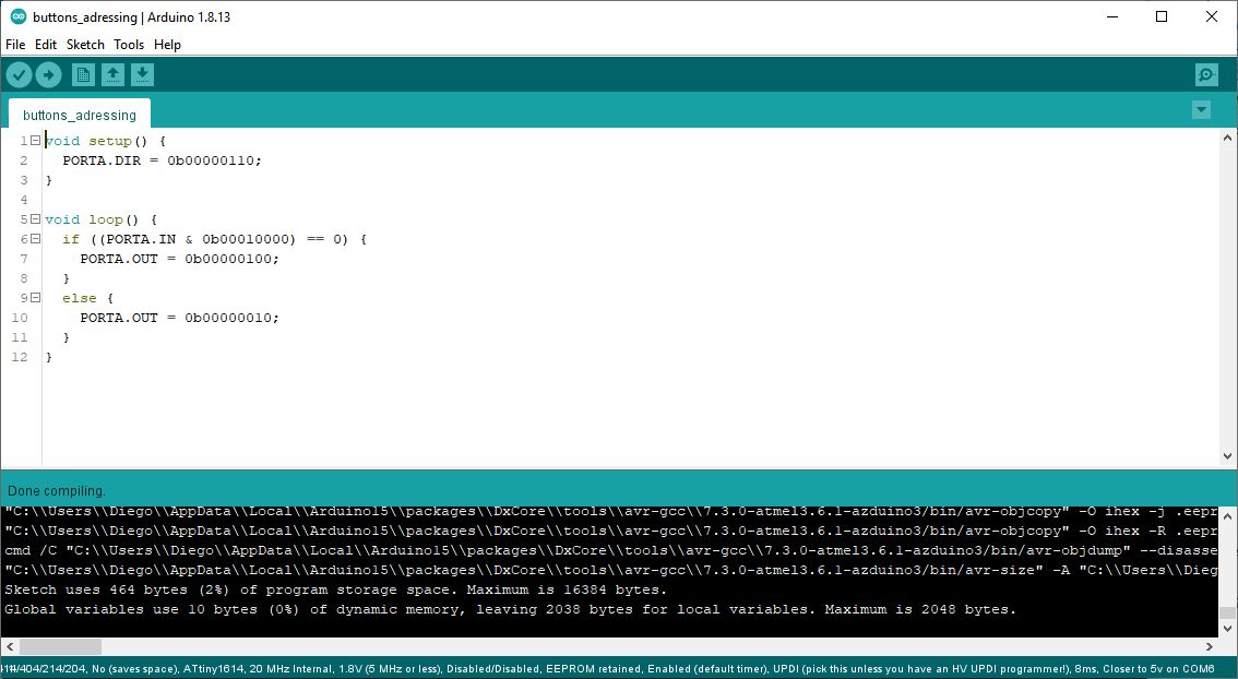
And then the button:
Here I had the chance to learn also about the bit operations:
- | OR: 1010 | 1100 = 1110
- ^ XOR: 1010 ^ 1100 = 0110
- & AND: 1010 & 1100 = 1000
- ~ NOT: ~ 1100 = 0011
Then, in order to try other way of flashing the microcontroller, I decided to try to do it from Terminal instead of doing it with Arduino IDE. So I only used Arduino IDE to compile the file .hex, and then I flashed it from Terminal.
I followed this guide provided in the documentation site for Fabacademy of Fab Lab Barcelona:
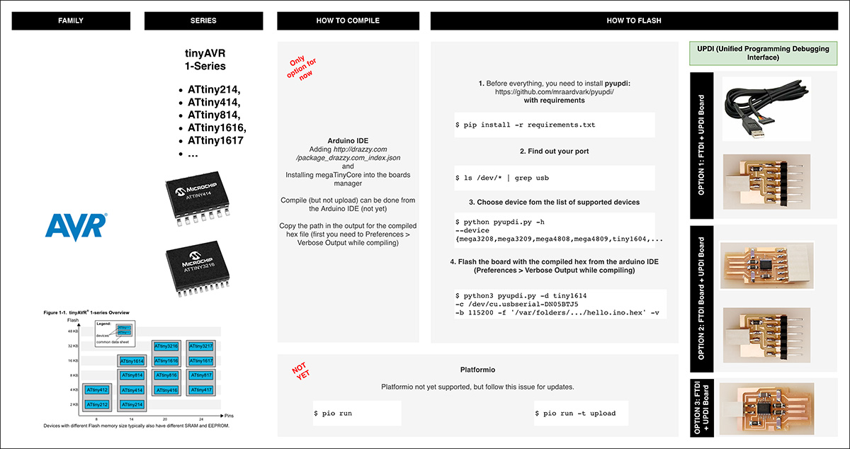
Although, the commands seems to be for MACOS, I managed to adapt it for windows with some help.
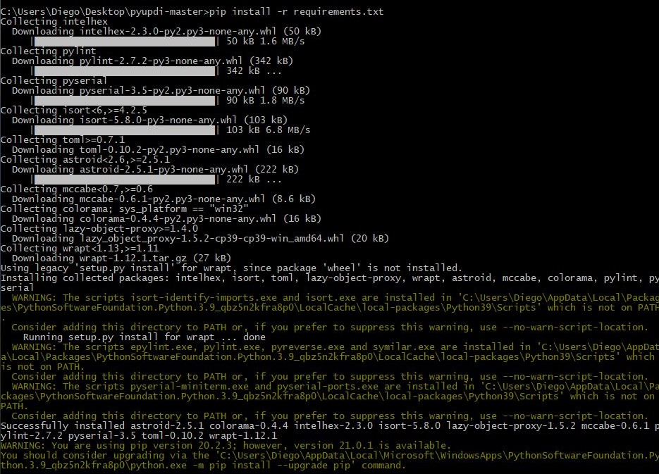
First of all I installed Python, and then pyupdi from https://github.com/mraardvark/pyupdi/ with:
pip install -r requirements.txt
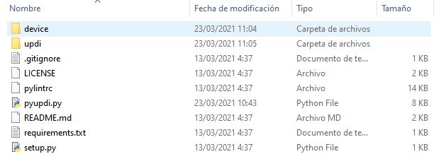
To install pyupdi you have to be in the folder where it is saved:
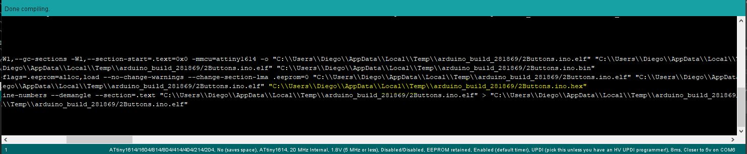
Then, I compiled the program in Arduino IDE and looked for the .hex file:
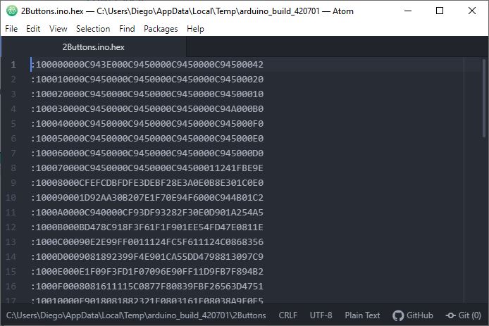
I opened the .hex file to see how it looks like:
Then I tried to flash the board with:
python3 pyupdi.py -d tiny1614 -c COM6 -b 115200 -f '.hex file'
Where the port COM6 is the one where I have conected the board
In the first attempt, I was giving the following error: "ModuleNotFoundError: No module named 'device'

In the end, the cause was an issue with the path, which I solved by movieg the file pyupdi.py to the main folder:
So, after that I was able to flash the board succesfully:

Conclusions:
As this week everything was new for me, I learned a lot. The first feeling is that is simplier than I thouhgth to do basic programing with Arduino IDE.
Then I also got to understand a bit better how a microcontroller works, and to learn how to extract key information from a microcontroller data sheet.
I also used this week to learn a bit more about Information Theory, by following this series of videos in YouTube that I found really interesting: https://www.youtube.com/playlist?list=PLbg3ZX2pWlgKDVFNwn9B63UhYJVIerzHL
One interesting thing about the assignment was to compare the size of the files by programming in different languages. Thus, the files that were programmed in C where smaller than the ones programmed with Arduino default language. I attach the comparison in the two codes I used:
Comparison in the blink code:
- Arduino code: 954 bytes
- C code: 786 bytes
Comparison in the button code:
- Arduino code: 714 bytes
- C code: 464 bytes
Files:
Arduino IDE code for button and two leds
Arduino IDE code for button and two leds in C
Arduino IDE code for blink of two leds
Arduino IDE code for blink of two leds in C