4. Computer controlled cutting
On this week I learned the operation of a laser cutter and the work flow for it use. The machine we have in FabLab ZOI is a
Group assigment
Work Flow
Laser machine details
- Supra cnc
- Made in ecuador
- Pipe:60 watts
- 110V
- Chiller
Before use
- Verifying that the evacuation pipe is well located.
- Clear the laser cutter's mirrors 
- Turn on the Chiller
- Turn on the ventilator
- Turn on the laser cutter
- Turn on the light
- Verify the origin location in the laser table
- Calibrate the altitude of the laser with the material that will be used
While using
- Keep the machine door closed
- Don't leave the laser cutter room while the machine is cutting
After use
- Turn off the light
- Turn off the laser cutter
- Turn of the ventilator
- Turn of the Chiller
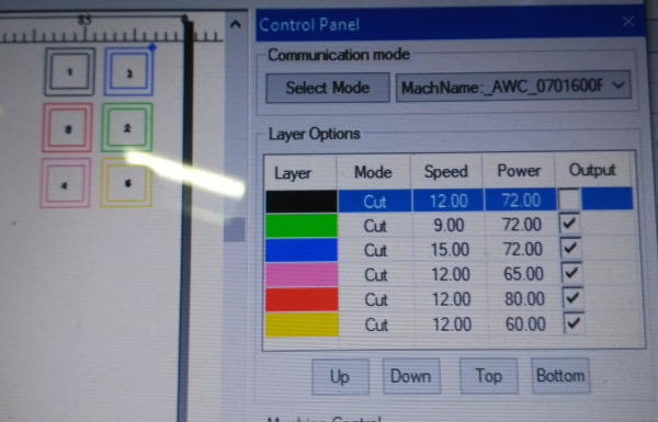
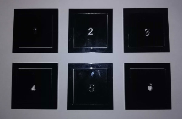
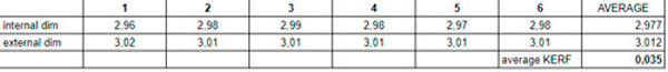
KERF
To know the kerf of the laser cutter machine we make an excercise. We Make 6 sketches of a square offsetted and we cut them with different time and power settings. I choose acrilyc 3mm for that.
Conclusion
Lasercutter is a machine which can catch on fire so it's important to be attentive to it while working.
It's important to take KERF into account on our designs, especially if we want to make press fit contruction kits
Parametric 2D design
2 years ago I learned, in a 3D printing workshop, what was parametric design with Fusion 360 and I remember that I reache to model some pieces.
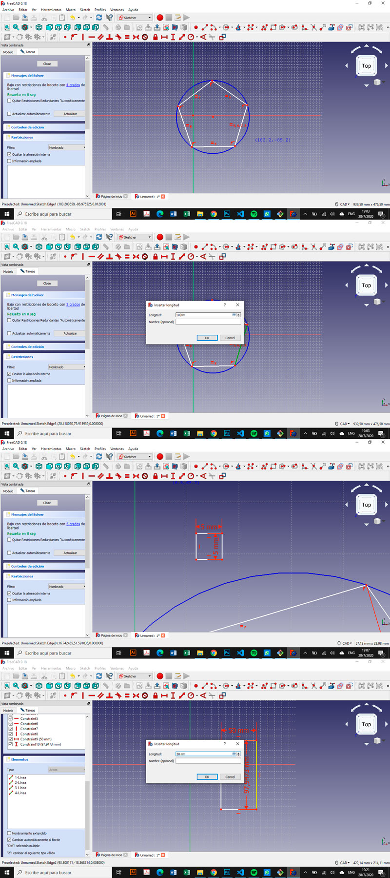
FreeCAD
I start with this software because I wanted to try something new and also because I saw some of Apeksha’s tutorials. But it was so hard for me to model and I had not much time to make the parametric construction kit, so I moved to Fusion 360.
Fusion 360
I was more related to this software but I didn’t touch at it for 2 years so I was more or less in the same situation that I was using FreeCAD. Nevertheless I found Fusion’s interface more intuitive and easy to use than FreeCAD’s.
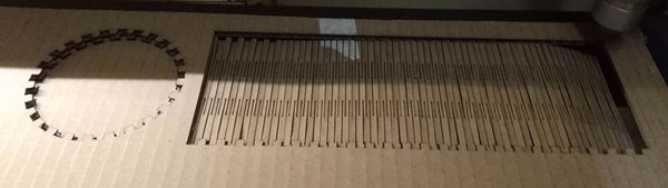
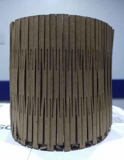
I wanted to make something related to my final project So I decided to make a “cardboard cup” with the finger joint and a blendign pattern. I create a circle and a rectagle first. (Now I realized that the dimentions of the circle’s circonference and the rectangle’s length were not related together).
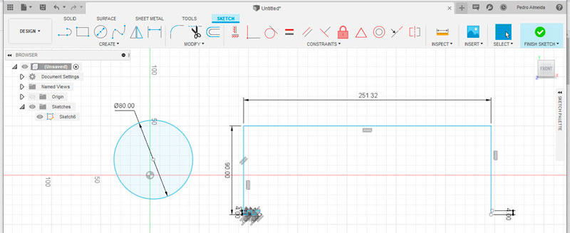
The second step I create the firsts “fingers” at the rectangle’s base. I wanted to make a cylinder so fingers and voids had to be relatively small, so I took the same thikness of the cardboard (4mm).
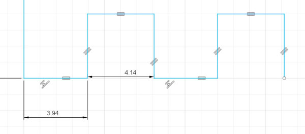
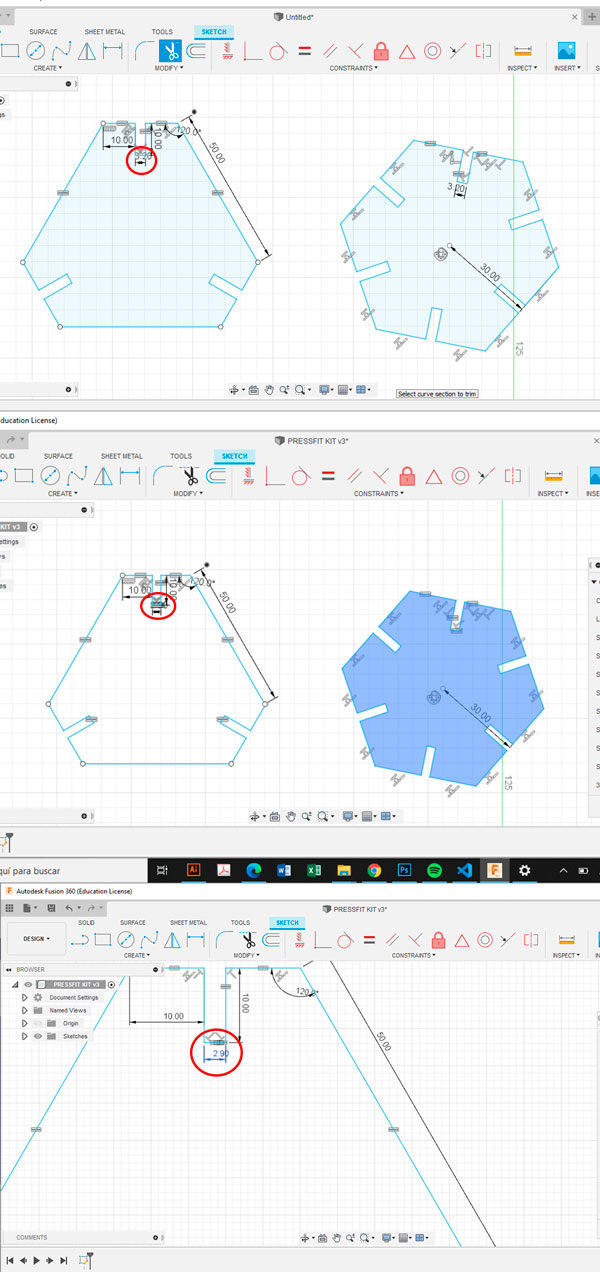
I put it some constraints like equal, coincident and parallel and I began to undestrand this way of modeling. I use the FreeCAD joints model Neil gave to us to determinate my finger joints dimentions.
Accounting the kerf I dimensioned:
- Fingers: 3,9 + 0.04(kerf) mm = 3.94 mm
- Void parts: 4,1 + 0.04 mm = 4.14 mm
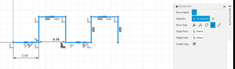
I wanted to copy and paste those first “fingers” until the distance of the rectangle were attained but I had some problems for relate all the elements. At this time I stressed enough to forget to take screeshots.
Thank to my tutor advice I reached to complete the pattern. He told me to make the complete sketch in a “non-precise way” and to add the constraints after that.
I had any idea of how to make a bending pattern so I search on youtube and I find this bending patterns video
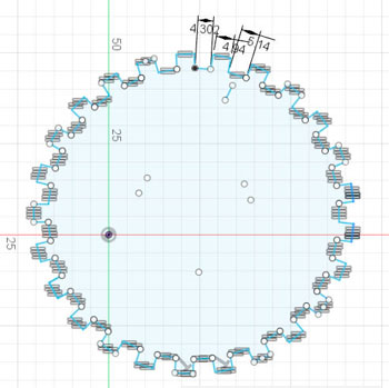
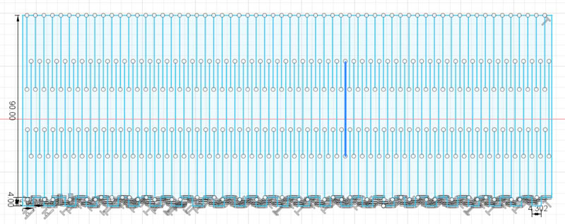
I sketched the circle in the way I wanted to do it with the rectangle at the first time. So I drew a first finger sequence and I mirrored/copy it. I repeated the step till my circle were completed. I was obligated to keep the last void part in a diferent dimension of all others.
Finally I saved the sketch in a .dxf file downloadable here.
Laser cutting
I already had experience with laser cutting because I’ve been working in collaboration with FabLab Zoi while a time but the machina was a Bodor 90x130cm.
RDWorks V8 - Software
I opened the .dxf file in RDWorks V8.
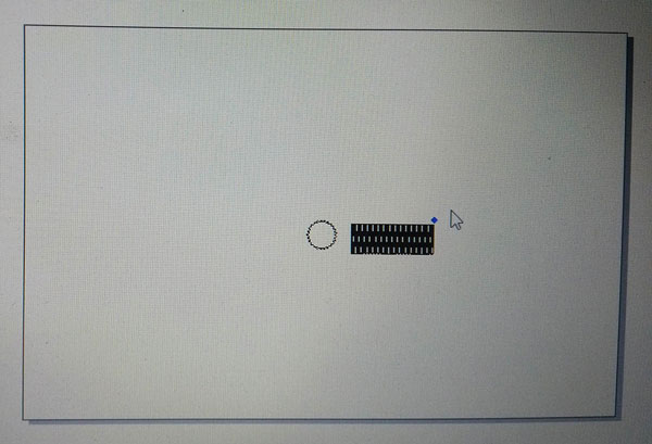
The first problem I had was that the sketch was opened in a diferent scale so I re-scale it using the measurment editor ubicated up to the left in the software’s interface.
Settings:
- Speed: 20
- Power: 70
Laser Machine
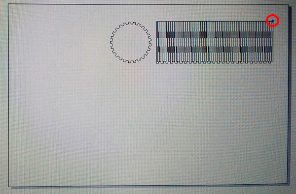
The blue point in the work ares indicates de origin point of the laser so is important to ubicate correctly the material to don’t risk outages outside the area.
For that there is the “Run box” button (showed here below in the Work Flow section). Clicking on it, the laser shows the area in which it will work.
Work Flow
- Ubicate the material
- Adjust the laser height with the stantard measure (there is a piece of wood to do that)
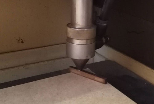
- Mark the origin with the “Origin” button in the machine or in the software.
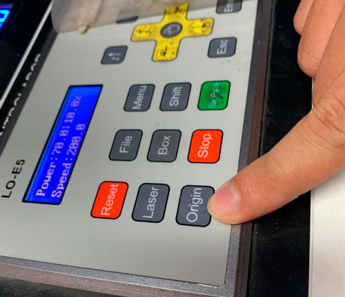
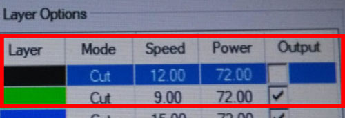
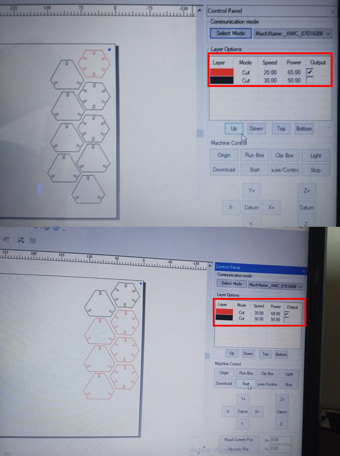
- Set Speed and Power cutting (checked box layers will be cutted, unchecked boxed will not)
- Download the file to the machine with the “download” button on the software
- Verify the cutting area with the “Run box” button on the software.
- Press “Start” on the software.

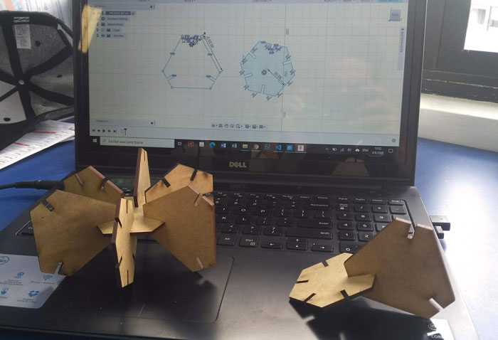
Press Fit Kit
With the design properly ubicated in the work area I proceed to download the file to the machine and star cutting.
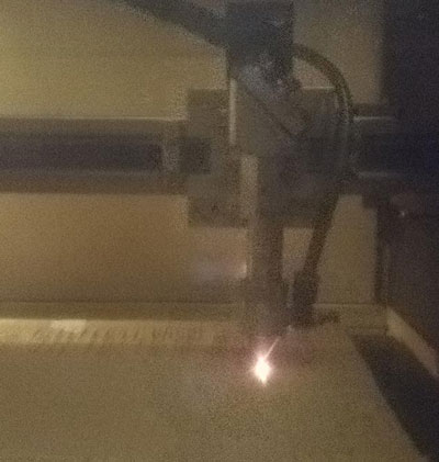
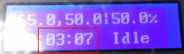
The cutting process had a 3:07 minutes duration.
And this is my HERO photo!
Download the file here
After that I realized that my pressfit kit couldn’t to be assembled in different ways and it was not very “pressfit” so I maked an other kit.
First I tried with 3.2mm but the fitting was to loose so I tried with 3mm and then with 2.9mm on mdf 3mm. This changement of dimentions was not a problem because of the PARAMETRICAL way the pieces were designed.
I tested Speed and Power on a pair of pieces first. There were not cutted completely so I increase de power.
HERO SHOT
Download the DFX file here
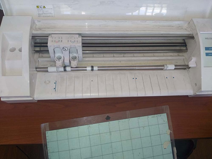
Vynil Cutting
We started this assigment with a brief introduction about the Cameo’s functioning.
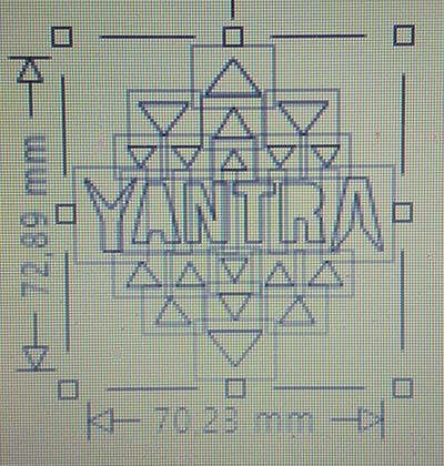
We check out the knife, the command screen, the sacrifice material, and the locking bar. After that I proceed to take a 2d design I wanted to cut and to save it in a dxf. file to open it in Silouhette Studio.
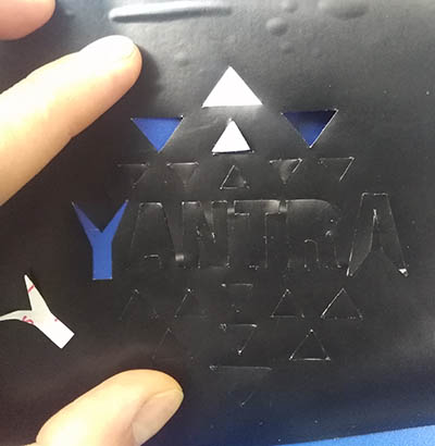
The first problem was that my design didn’t appear completely in the Silhouette software. The “A” and “R” holes were missing.

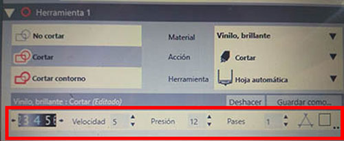
Anyway I maked the first cutting with this little graphic error on theses settings up here. Even if the test made before the cutting was apparently ok.
The distance of cutting was to much depth so the knife cut even the paper under the black layer.
After that I change the sentings with:
- Depth: 2
- Speed:5
- Pressure: 11
- Passes:1
This time the cutting was ok.
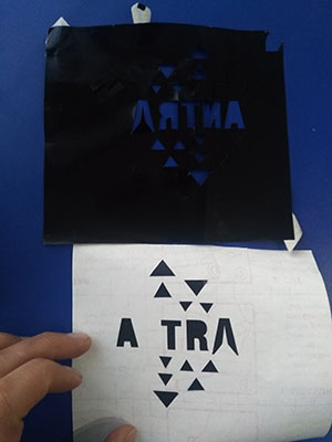
I tried to take out the “negative” part to make the transfert process only with the positive one. But it was to much hard to leave the little parts on the vinyl transfet paper. So I failed an other time.
This time I kept the same settings, I make directly the process on the hole design and I trasfert it on my laptop.
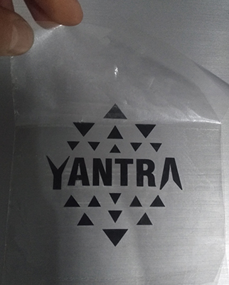
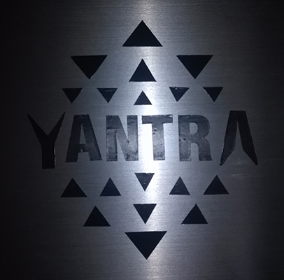
You can download here the logo’s file.
Learning outcomes
- [x] Demonstrate and describe parametric 2D modelling processes
- [x] Identify and explain processes involved in using the laser cutter.
- [x] Develop, evaluate and construct the parametric construction kit
- [x] Identify and explain processes involved in using the vinyl cutter.
Have you
- [x] linked to the group assignment page
- [x] Explained how you parametrically designed your files
- [x] Documented how you made your press-fit kit
- [x] Documented how you made your vinyl cutting
- [x] Included your original design files
- [x] Included your hero shots