Final project
Final Project Ideas
For the final Project I had two principal ideas: - The first one was a device that could identify a kind of micro-vibration called “form emission”.
The study of “form emissions” was developed in the 1930s by André de Belizal and Léon Chaumery, two French physicists who, against the tide of everything that was done at that time in the field of physics, explored the world of microvibratory physics. This study led them to discover that objects emit a wave or vibration whose characteristics are closely related to their geometric shape.
At that time those physicists measured “form emission” with pendulum devices. Being aware of this fisical influence about shapes in people’s spaces and bodies (because of the vibratory nature of all things) turns important to know what kind of shapes are positive or negative for living beings’ health. In the same way of this project I thought it could be also an smathphone app that “scans” objects and make a kind of harmonic shape assesment based on mathematicals algorithms and geometric patterns.
- The second idea was a Smart Coffee Mug that keeps people’s coffee or hot drinks warm.
This one was more supported by my tutor. He said that in the Fab Academy context, it will be a better project thant the other one. I was agree, and I thought that in a comercial way, this product will be more demanded than the other one.
Smart Coffee Cup
I want to develop a product that solves a very common problem and therefore has an excellent reception in the market. One of the most repeated problems I noticed, by my own experience, on an office work context, is that people’s coffee cools long before they finishes it.
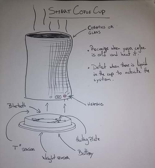
This cup will be able to detect when your coffee has cooled to turn on its warming system. It will reconize also when there is no more liquid inside to automatically turn off. The cup will be made in ceramics or glass with a sophisticated and organic design. The operation of the product will be programmed with an application with which it will be possible to adjust the temperature to the consumer’s preferences.
2D and 3D design
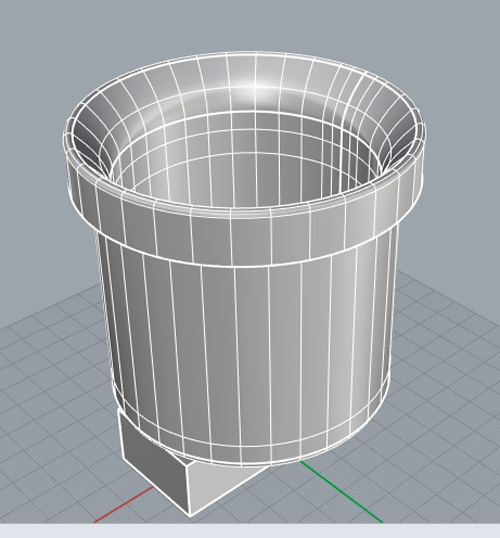
I want a organic-sophisticated design concept for the cups aestetic, so I make a first design based on a bamboo sculpture I made before.
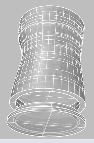
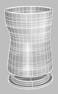
This first design evolved to this one:

After the electronics analisis and some temperature tests it turned into that.

Files
Download here the first mug’s 3D model
Download here the second one.
Electronics design
First try
Before starting with the circuit design software I choose a Hello World board to redraw it.
Hello Wold's BOM:
| Part | Value | Device | Package | Description | |
| C1 | 1uF | C-EUC1206 | C1206 | CAPACITOR, European symbol | |
| IC1 | ATTINY44-SSU | ATTINY44-SSU | SOIC14 | ||
| J2 | FTDI-SMD-HEADER | FTDI-SMD-HEADER | 1X06SMD | ||
| R1 | 10k | R-EU_M1206 | M1206 | RESISTOR, European symbol | |
| R2 | 150 | RES-US1206FAB | R1206FAB | Resistor (US Symbol) | |
| R3 | 10k | RES-US1206FAB | R1206FAB | Resistor (US Symbol) | |
| R4 | 0 | RES-US1206FAB | R1206FAB | Resistor (US Symbol) | |
| S1 | 6MM_SWITCH6MM_SWITCH | 6MM_SWITCH | OMRON SWITCH | ||
| U$1 | LEDFAB1206 | LEDFAB1206 | LED1206FAB | LED | |
| U$2 | TERM-1X03'-FABLAB' | TERM-1X03'-FABLAB' | ED555DS-3DS | 3.5mm terminal block, 3 positions ED555-3DS as found in the fablab inventory. | |
| U$3 | AVRISPSMD | AVRISPSMD | 2X03SMD | ||
| XTAL1 | 20MHZ | RESONATOR | EFOBM |
Based on that I added to the board a termistor for adapt it to my final project.
| U$2 | TERM-1X03'-FABLAB' | TERM-1X03'-FABLAB' | ED555DS-3DS | 3.5mm terminal block, 3 positions ED555-3DS as found in the fablab inventory. |


Here you can download the design files:
Second try
Components
| Part | Value | Device | Package | Description | MF | MPN | OC_FARNELL | OC_NEWARK | POPULARITY | XTAL |
| 5V | REGULATORSOT23 | SOT23 | ||||||||
| 11.1V | PINHD-1X2/90 | 1X02/90 | PIN HEADER | 24 | ||||||
| C2 | 1uF | CAP-UNPOLARIZEDFAB | C1206FAB | |||||||
| D1 | LEDFAB1206 | LEDFAB1206 | LED1206FAB | LED | ||||||
| IC2 | ATTINY44-SSU | ATTINY44-SSU | SOIC14 | |||||||
| LED2 | LEDRGBOLD | P-LCC-4-3 | OSRAM | |||||||
| LM1 | PINHD-1X3 | 1X03 | PIN HEADER | 92 | ||||||
| Q1 | NMOSFETTO252 | TO252 | MOS FET | |||||||
| R1 | 0 | RES-US1206FAB | R1206FAB | Resistor (US Symbol) | ||||||
| R2 | 1k | RES-US1206FAB | R1206FAB | Resistor (US Symbol) | ||||||
| R3 | 0 | RES-US1206FAB | R1206FAB | Resistor (US Symbol) | ||||||
| R4 | 0 | RES-US1206FAB | R1206FAB | Resistor (US Symbol) | ||||||
| R5 | 0 | RES-US1206FAB | R1206FAB | Resistor (US Symbol) | ||||||
| R7 | 1k | RES-US1206FAB | R1206FAB | Resistor (US Symbol) | ||||||
| R10 | 10k | RES-US1206FAB | R1206FAB | Resistor (US Symbol) | ||||||
| R11 | 499 | RES-US1206FAB | R1206FAB | Resistor (US Symbol) | ||||||
| R12 | 499 | RES-US1206FAB | R1206FAB | Resistor (US Symbol) | ||||||
| R13 | 499 | RES-US1206FAB | R1206FAB | Resistor (US Symbol) | ||||||
| U$3 | AVRISPSMD | AVRISPSMD | 2X03SMD | |||||||
| U$4 | WIRELESS-BLUETOOTH-HC-05 | WIRELESS-BLUETOOTH-HC-05 | WIRELESS-BLUETOOTH-HC-05 | Bluetooth Transceiver Module based on HC-05 board | ||||||
| V | W237-02P | W237-132 | WAGO SREW CLAMP | unknown | unknown | 10 | ||||
| XTAL1 | 20mHz | RESONATOR | EFOBM | 20mHz |
REGULATORSOT23 was replaced by LM7805
Electronic Design Process
The following design process was made after some temperature tests with the principal output of my project, a Nichrome wire. To control it temperature I needed a transistor so I help my schematic design with those following examples:

I was familiar with most components except bluetooth, mosfets, and voltage regulator.

Here I added a voltage regulator to power the microcontroller with my 11.1V battery and I connected the microcontroler to GND.

Here I connected all VCC ports to VCC.

The last step before the PCB board design was to connect the RGB LED to GND.
After that I started the PCB design. To optimize space I will place the bluetooth device on the back of my PCB.

After this first phase my tutor told me that lines were to much thin. I had problems to change the width unity from mil to mm so he help me for that and for changing all the lines’ widht at the same time.

- For changing all lines’ width:

Select lines to change

Type the command and ENTER:
CHANGE WIDTH 0.4 (width value to change to mil or mm)

Right CLICK outside the lines and click on Change: Group
DONE
After that my tutor told that I had to replace some components so I took the oportunity to ask how to draw a reference circle for my PCB’s shape.
- To import a DXF file:
Create a dxf file with the shape you want to import
Click onto the UPL button

type dxf on the browser
Click on import dxf
Click on Aceptar

Choose the correct unity
Find your dxf file
choose milling for the layer
Click on OK
DONE
- To replace components without deleting them:
Select the component you want to replace

Click on the replace button
Select the new component
Click OK
Re-click on the old component
DONE
Here the files of this work:


PCB production
With the PCB design finished, I exported and image from EAGLES’s board:
Click on File / Export / Image

Here set the window like in the image. Pay attention to select the Monochrome box.
After that generate the GCode in MODS

For the profile I maked the image exporting process, I imported it to Paint and I painted the inside surface in black, saved the file in png and opened it in MODS.
My lines were very thin because of choosing the climbing option instead of conventional. A line connected directly to the microcontroller was entirely gone.

I started soldering the Atmega 328p, after that I fixed a line with a piece of copper to replace the damaged one.

When I finished soldering all the components I connected the PCB to the programmer and to the PC to make them comunicate together.

The PCB was comunicating correctly with the PC so I passed to the bootloader burning to upload the program to the PCB.

But I had this bootloader burning error.

After that the PCB did not comunicate with the PC anymore.

I was told that in those cases the microcontroller is blocked and it is not possible to unblock it. So I was forced to unsolder the microcontroller to weld a new one.
The second time I had the same problem so I had to redesign a PCB with a Attiny44 microcontroller.
The files of this PCB are downloadble here:

I had to unsolder the components of the other PCB to solder them on the new one.


This time we used an other PC to the Bootloader burning and we tried to establish communication with two diferent programmers.
We maked the same process. Here we had different issues:
- oscillator was turning anormaly hot
- there was a connectivity between VCC and GND
- PCB communicated succesfully once and then stopped, we were not able to make it an other time
So we desoldered the microcontroller, the transistor and the oscillator.
After that I re-welded a new microcontroller previously tested, proved comunication and it worked correctly.
We burned the bootloader successfully with a 8hz/internal timer configuration and finally I reach programming the PCB on my computer.


Now when the microcotroller was programmed I must test it with the inputs and outputs welded on the PCB.

First outputs were not reacting correctly to the sensor lecture. RGB led blinked senseless and the white led didn’t turn on when it should. So I replaced those leds by other ones with no success. My tutor told me that maybe the problem was originated by the sensor so I replaced it too. However the wrong functionning kept happening.
We decided to weld the HC-05 Wireless module to read the signal emmited by the sensor.

Reading the sensor’s signals we realized that there were an error in the code, we corrected it and after that PCB worked really good.
Embeded programming
I writed a code to make my termistor interact with an output.

Termistor board’s code | PROTEUS simulation
int valor=0;
double temp=0.0;

void setup()
{
  pinMode(2,OUTPUT); //Configuracion del pin
  digitalWrite(2,LOW);//Inicia el pin en un estado bajo 0 logico o 0 voltios
}

void loop()
{
  valor=analogRead(A3);
  temp = valor * 5.0 * 100.0 / 1024.0;  //convierte de 0 a 1023 en grdaos centigrados

  if (temp > 50.0)
  {
    digitalWrite(2,HIGH);
  {
    }
  }
  else
  {
    digitalWrite(2,LOW);
  }
  }
The code works in the proteus’ simulation but I had to try it on matter.

Termistor and RGB led | Tinkercad simulation
In the way, I learned to use Tinkercad and I adored that software. It allows to create simulations with virtual components and the code is automatically written in Arduino. This time I make a circuits to change the colour of a RGB led with the value variation of a thermistor.
Downlowad here the code of my Tinkercad’s simulation.

Electronic and programming test (Atmega328p - Arduino’s microcontroller)
For this part I maked a physical simulation with all the components I’ll use for my PCB with an Arduino on a “white board”
On the first one I tested the comunication beetween the LM35 sensor and the RGB. We realized, after some failed attempts, testing the color changement of the led with the temperature variation, that led was spoiled.

Here the printed values were readed from analogRead‘s data reception instead of the temperature’s variable temp.
I changed the code line
Serial.println(analogRead(A0));
by
Serial.println(temp);

Now the printed values corresponds to the real temperature in Celsius degrees but led was not changing with the temperature variations because output pin’s kept reading the Analog value and not the temperature.

I changed the variable after each if and the RGB values (is right here that I realized led was spoiled).

This time I learned that there are leds that have to be connected to GND and others to VCC. And this fact change the programming way of the output.
After I make the same test adding the heating coil, the transistor, the voltage regulator and the battery simulated by a power source.

Here the whole system, including the Arduino, was powered by the source.

I added a line to the code to include de heating coil output on the void loop
analogWrite(3, 255);
For turning on the heater
analogWrite(3, 0);
For turning it off
Code of the final succesful test here
Heating system programming video
For adding the Atmega328p microcontroller to the Arduino’s library I followed this tutorial.
I never reached to upload the code to the Atmega328p’s PCB because it turned blocked both times I tried to burn the bootloader into. I even burned a programmer’s microcontroller trying bootloader burning. So I redesign a PCB, this time with an Attiny44.
Attiny44
After welding the HC-05 Wireless Bluetooth I readed the sensor’s signal and the temperature values were wrong.

Then we found an error in the code. The signal of an input “analogRead” has to be readed once only. I corrected the code an when uploading the program an error occured.

After that we tried uploading the code with an other programmer but this time the PCB stopped comunicating with te PC. We thought the microcontroller was blocked again so I unwelded it and welded a new one. With this new microcontroller the comunication problem kept. There were no more Attiny44 so I unwelded one from a existing PCB, I tested it before and I repeat the process. This time it worked. This process took an entire afternoon.

I programmed this new microcontroller and it kept not working correcly. After that We found an other code error.
My sensor pin was misconfigured. Because of that I learned that is not necessary to configure an analog reader pin in the void setup part of the code, it must be mentionned as analoRead(pin) in the void loop section only.

The sensor’s microcontroller’s pin was misconfigured. Because of that I learned that is not necessary to configure an analog reader pin in the void setup part of the code, it must be mentionned as analoRead(pin) in the void loop section only.

After this changement into the code, the temperature values reading was finally right. But the outputs were not running CORRECTLY. So we found that this was a digital signal output and not an analog one. So I changed that writing configuration.

After that I make a simulation in PROTEUS

The actuator was ok and the RGB led was wrongly connected.

Now all was ok in the simuation but, on the PCB, the white led shown the actuator state was unstable and RGB was still working wrong.
Then we find that, for Arduino programming, the pin number 3 of Attiny44 is related to 2 pins.

So I replaced that by (A3) in my code. I replaced all analogWrite>s by digitalWrites because I was not using analog signal colours. Now the actuator’s led was turning on correctly but blinking and for the rgb, only the Red light was working.
After a realized that I was connecting the RGB this way
R - 13 B - 12 G - 11
Istead of the Schematics way:
R - 11 B - 12 G - 13
By correcting that RGB works correctly except by the fact that the blue light was not correctly welded because of its resistor that was spoiled. After replacing that resistor RGB finally works prefectly. We solved he actuator’s led problem by replacing it’s 1k resistor by a 499 one.
Now the new problem was that serial comunication was not printing ok the sensor’s data.

Apparently that is because of the 20hz oscillator. There is a posiibility to reburn the bootloader with internal 8hz oscillator but at this point I don’t want to risk an other microcontroller blockage, so I’ll leave the bluetooth temperature control for after.
Computer controlled machining


For the mugs external layer I want to use bamboo so I designed some rings to be cutted on a 20mm bamboo board. You can download those files here:
I had a problem with the CNC and finally I couldn’t make the cutting, the next day they were going to move the machine to the new lab place so I had to find another way to make the external layer for my mug.
So my tutor told that I could make this part with acrylic and laser cutting.
System Integration
Once my ceramic mug went through the oven I test the embeded resistance to know what temperature it could reach with 11.1V, my battery voltage. It reach almost 75 degrees celsius. After that I connected it to the PCB to try it all together.

Fist tests were not going write because red led’s intencity were progressively decreasing until turning off. I maked various tests and then I decided to try with a new one. That works at the beginnig but after some time the problems returns.
Finally I change the red led 499 resistante by a 330 and all work better.
An other problem that appears was that the voltage regulator was getting too hot. I tried to solve this problem changing the leds by SMD ones, my tutor told me that this ones will cosume less energy. So I changed them but the I still having the same problem. In addition to that my leds were not stable enough, they were flickering. After that I realized that the led RGB that I was using was a common annode and my pcb had been designed for a common catode. I solved that cutting the line connecting the pcb’s GND pin and the common rgb’s pin and connecting this one to Vcc. After that RGB works better but keep flickering. In this process I changed the code for rgb pins because common ANODE RGB coding is the opposite of common CATODE.

Codes dowloadble here:
After that I noticed the voltage regulator was turning to hot so I replaced it by a bigger one with a more powerfull current capacity and I added a thermal diffuser to it.


Finally I joined:
- Ceramic mug with nichrome coil embeded in
- PCB
- 11,1 V Battery
- Acrylic cases
Heating system
After thinking about many posibilities for the heater system I decided to make it with a nichrome wire heated by a battery. Just like a vaporizator.
I didn’t know the voltage and current values I needed to be able to heat a certain amount of wire to reach the 65-70 Celcius I want to reach. So I make some tests.
My tutor find this tutorial for me and he adviced my to follow the video steps for my firsts tests.
Nichrome tests
1mm diameter Nichrome
I took 6cm of 1mm diameter Nichrome wire more or less, and I connected it to a generator. The wire heated very fast but with high current values . I need my system works with a battery so I have to adjust the wire to a battery power.
Nichrome wire #27 + Mosfet
I bought a thiner Nichrome wire #27:
Diameter: 0.3607 mm Cross section Area: 0.102 mm2
8cm of this wire approximately heated to inncadescence in few seconds with 10V and 6A maybe.
For this first heater system test I search an example for an Arduino - ventilator - transistor system and I make a test with a DC motor.


The motor DC runs following the following code instructions:
After that I replace the DCmotor by a few centimeters of nichrome wire.

It reach 57 celcius degrees.
#27 Nichrome wire + aluminium mug
This time I tried to heat a longer nichrome wire wrapped around an aluminium mug. So I cut the mug to wrapped the wire just on de liquid contact surface.

First I make some tests with a energy source with the wire only to measure the temperature variations in fonction of the voltage varietions.

After that a make the test with the aluminium mug and some water.

The wire get very hot only in the split ends, where the connections where made; it reached around 40 celcius degrees in the middle of the wire but in the center of the mug there were not temperature changes.
I realized that the wire in its original straith shape will never be able to heat the entire mug because of the lost of thermic energy. So I tried with a flat shaped nichrome wire.
Flat Nichrome wire + teflon + aluminium mug
I also found that the fact that the thermos is conductive took power away from the cable wire so I found some teflon tissue and I placed it in between to isolate the wire from the mug.
On the first tests with the new wire I reach to heat the entire wire very fast but the necessary current was to high. First I make a test with the generator.

The second test was made with the battery (4A - 11.1V). Before the test the battery was more or less 10V.

The wire temperature reach 40 - 50 celsius degrees and the temperature at the center of the mug reached 35 - 40 celsius degrees. After this test my battery was fully downloaded.
#27 Nichrome wire rolled up
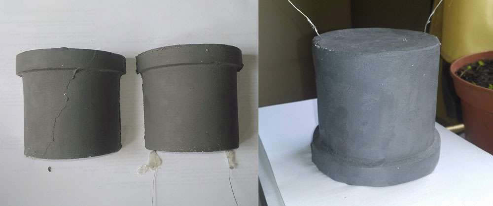
This time I took 70 cm of the thin wire and I rolled it up on a coil shape. With 7.3 V, and less than 1 A it reached almost 150 celsius degrees and it performance in relation with a ceramic mug was very acceptable. The interior of the mug reached almost 50 celsius degrees with a very low amperage consumption. So we decided to make it this way.

Conclusions
- The thin straight wire is to wick to transfer, efficiently, high temperatures to a bigger body.
- Aluminium is a usfull material for this project but it take to much energy away instead of keeping it within. In this way, ceramic has a better performance than alumnium.
- The flat Nichrome wire was ok for a high amperage battery but not for the one i’m looking for (1000 mha - 11.1V)
- The coil shaped nichrome wire will be embebed into the ceramic mug casting.
Molding and casting
For this part of my project I make a 3d model of my mug first.
Then I designed the mold to be milled. Due to the complexity of making a cup in one piece, my tutor told me to make two half cups and stick them together.
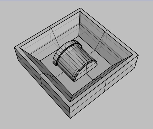
I cut 4 MDF squares of 3cm and I stick them to have 2 blocks of 6cm width.
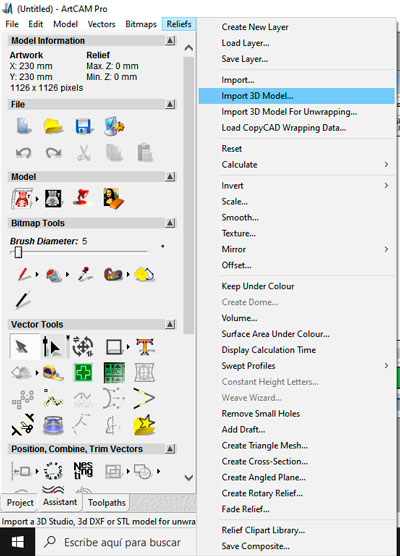
Those blocks took one entire day to dry, so at the next day I proceed to prepare the GCodes for the milling. For that I used Artcam, a CNC software.
First of all I create a model with the extact dimentions of the material I was going to use.
Then I imported the .stl file downloadable here
Make the following settings
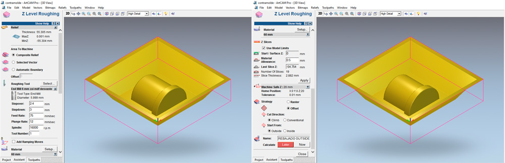
And create the toolpath with the NOW button.
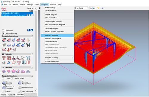
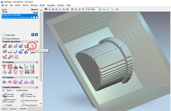
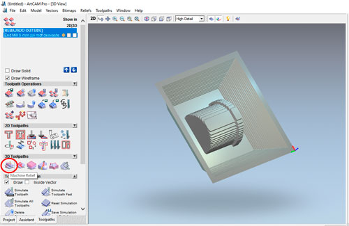
Look at the milling result with the simulator
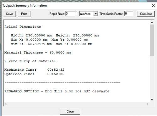
See the approximative milling time with the toolpath summary button
Once I was agree with I was going to have as result I saved the toolpath.
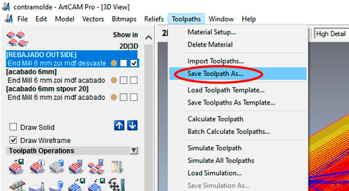
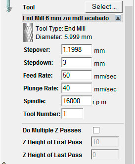
Next was to prepare the finishing toolpath. For that I choose the Machine relief button.
And make the following settings
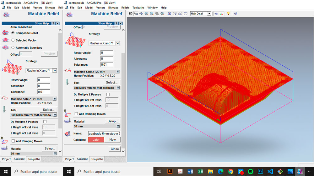
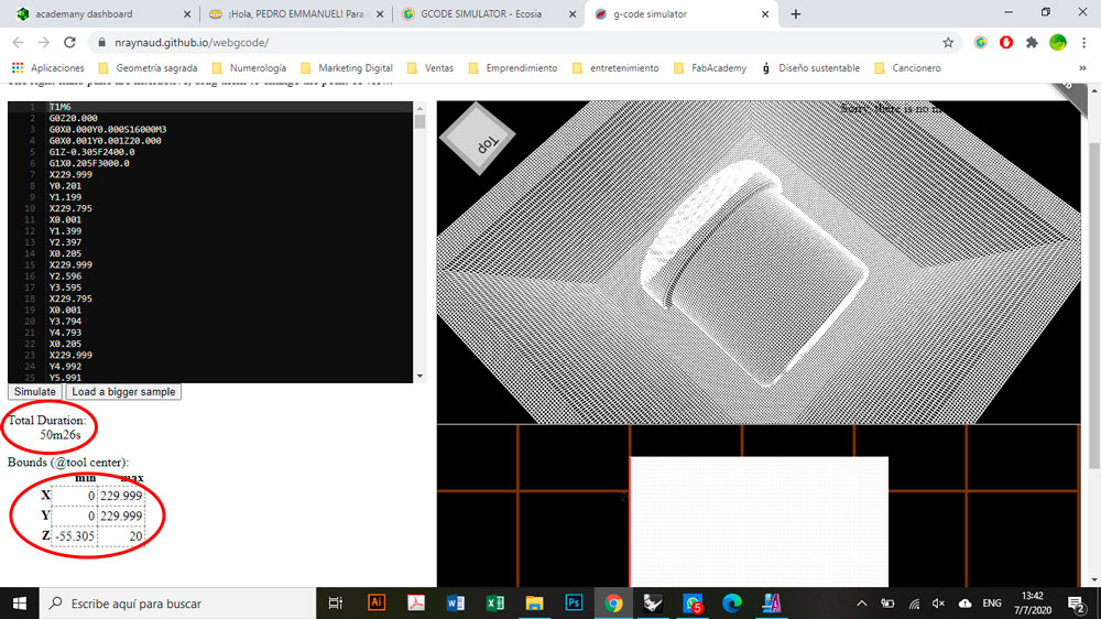
Then I create de toolpath ant I visualized it in this site. This webpage allows us to have an aproximation of the milling time and gives us the maximum and minimum x, y and z coordinates.
Then I passed to the machining process.
First the MDF block was fixed.
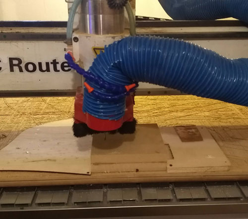
After I run the GCode
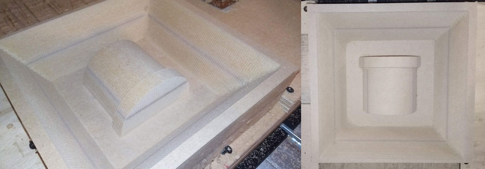
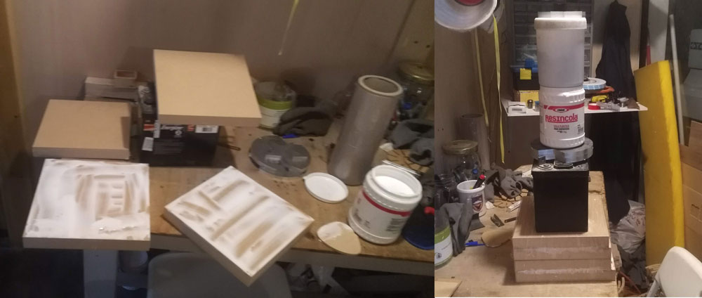
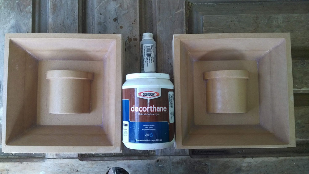
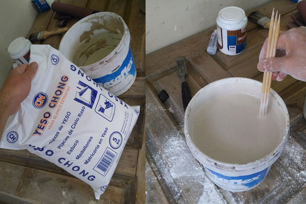
After that I sand the molds and I applied 2 hnds of wood sealer to avoid the wood absorbe the cast humidity.
Once the plaster was dry I removed the molds. The adhesion was strong so I was forced to hit hard and the molds broke, so I glued them together with contact cement.
Then I poured the slip into the molds placing the resistance in the corresponding base of the cup.
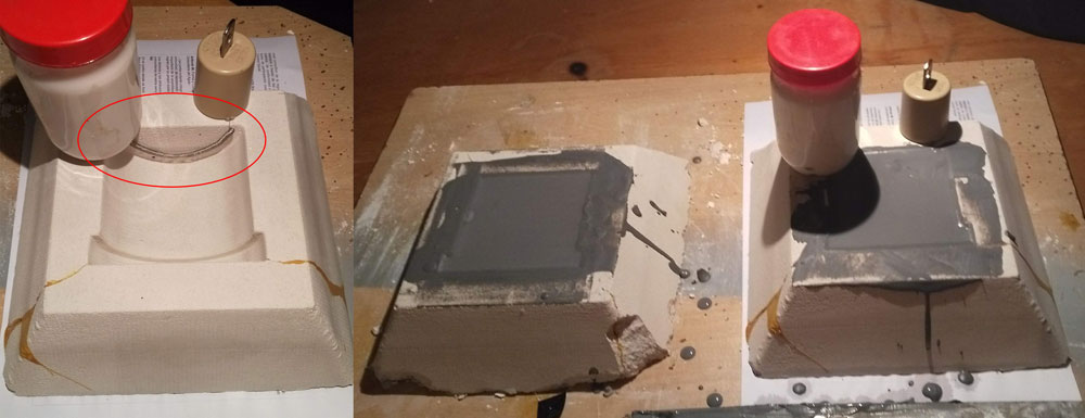
I waited for the hardened clay wall to completely cover the coil, then emptied the excess. I let it rest.
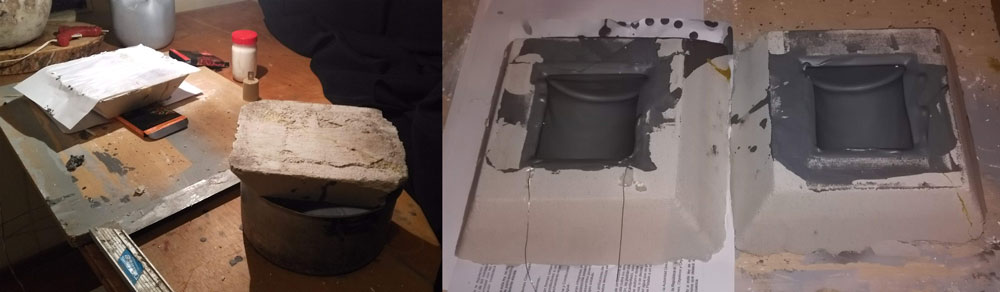
The day after that I unmolded the pieces and stick them in one piece.