10. Input devices
Sensing something | Group assignment
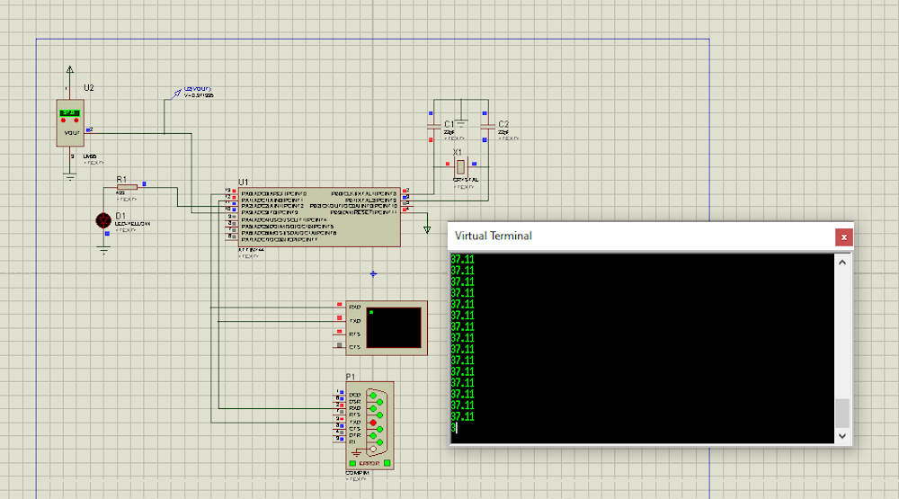
This assigment was completed in the embeded programing week. I used Proteus to make the lecture of my Input, which in this case is a termistor lm35.
First o all I import all the components I need:
- microcontroller Attiny44
- Xtal 20Hz
- FTDI
- Termistor LM35
- Virtual Terminal
After that I make the connections between each component to the respective pins and I introduced the code in the microcontroller settings.
#include <SoftwareSerial.h>

SoftwareSerial ftdi(1, 0); // RX, TX
int valor; //entre 0 y 1014
double temp;
char dato;

void setup()
{
 ftdi.begin(9600);
}

void loop()
{
  valor=analogRead(A3); //
  temp = valor * 5.0 * 100.0 / 1024.0;  //convierte de 0 a 1023 en grados centigrados
  dato=ftdi.read();//leo un dato de comunicación
  ftdi.println(temp); //imprimir

  delay(10);
}
The temperature was printed in the virtual terminal every 10 milliseconds.
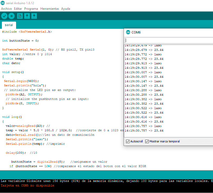
I made a lecture of the sensor with serial comunication between the board’s simulation and the Arduino’s Serial Plotter. You can see that in Embeded programming‘s week in the Serial Comunication exercise ‘s section.
Learnings
Interfacing
Interfacing an input device means that we need to manifest the input’s read values into characters or graphics for us to be able to read them too. For that we need to add to the circuit a serial comunication device like a FTDI or a bluetooth. With one of them we can open a virtual terminal or a serial plotter to see the values readed by the input. The enablement of that serial comunication is detailed here.
Physical property and measured results
There is a voltage emited by the input in one of it pins.That value is characterized by the amount of energy cosumed by the input device. The electric current enters through a VCC port (5V), passes through the component and continue through the GND pin. The amount of energy consumed is manifested by a signal on the pin connected to the microcontroller. This is an Analog value (it means that it can be any entire or decimal number between 0 and 5) which enters in the microcontroller by an ADC port. This signal is interpreted by the microntroller following the code’s conditionings and transformed into a digital signal. This signal can be used to run an actuator in a HIGH/LOW or ON/OFF way.
If I need the reaction of the input reading to be variable instead of “binary”, the input device has to be connected to an analog pin. In this case the 5V range of possible values is readed by the microcontroller as a number between 0 and 1024,and the code must contain a mathematical formula to convert this variable and abstract value into a real unit of measurement.
Design and fabrication process
Previous design process example
Previous fabrication process example
Programming process
- Start a Serial comunication between arduinos software and my board simulation.
- Set the serial comunication ports (RX: receptor and TX: transmisor)
#include <SoftwareSerial.h>

SoftwareSerial ftdi(1, 0); // RX, TX
- After that we create and label the variables
int valor; //int allows to write a number between 0 y 1014
double temp; // Double allows décimal numbers
char dato;
- Then we run the comunication
void setup()
{
 ftdi.begin(9600);
}
- And we create the reading loop
void loop()
{

  valor=analogRead(A3);
- Here I labled the port by wich the microcontroller is receiving the input’s signal with one of my variables name.
temp = valor * 5.0 * 100.0 / 1024.0;
- Convierte de 0 a 1023 en grados centigrados // This formula tuns the abstact value into celcius degrees.
dato=ftdi.read();
- Leo un dato de comunicación// Gives to the “dato” variable the value of the serial comunication lecture.
ftdi.println(temp);
- Print the lecture in the a Virtual terminal
  delay(10);
}
- Wait 1/100 seconds to read the loop again. 1 second=1000
Problems
When I had soldered all the components I tried to make the comunication test between the microcontroller and the computer but they were not comunicating. After some time I make it.

Once the board was programmed, there was not lecture in the serial monitor. So I tried with an FTDI module instead of the FTDI wire. Apparently there was a problem with the dirver in the wire case.
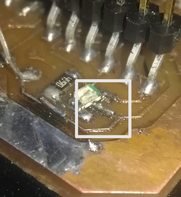
Before trying to read the sensor with the FTDI module I discovered a wireless line under the led between FTDI’s VCC pin and the microcontroller’s VCC pin. I solved it with a tiny cupper wire.
With the module the lecture run pretty good.
Original design files and source code
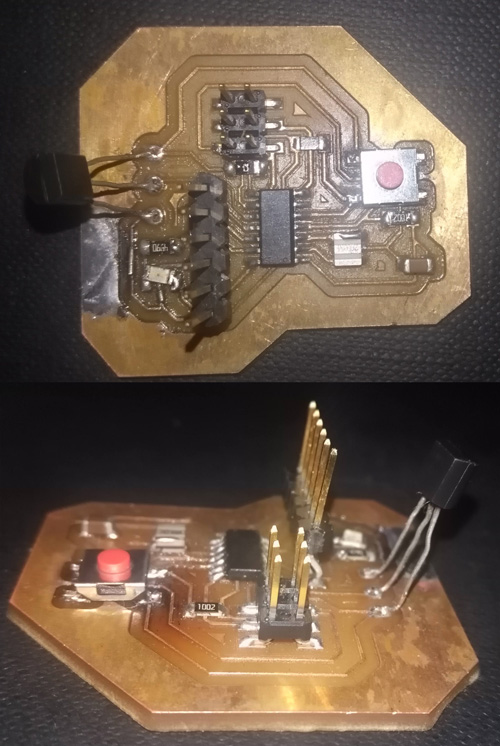
Hero Shoot
This board soldering was incomplete (because of the pandemic) so I finished to solder it with a button and a LM35 (temperature sensor). The problem was that when I wanted to introduce the program, the board didn’t comunicate with the pc so I did not reach to program it. I will try again, but the simulation works correctly.
I tried once more and this time it worked so I could program the board.
Temperature sensor lecture video
When I heat the sensor with my fingers the lecture turns very high because of a circuit crossing during the touching but after y reads 28 celsius degrees instead of 25.
Learning outcomes
- [x] Demonstrate workflows used in sensing something with input device(s) and MCU board
Have you?
-
[x] Linked to the group assignment page
-
[x] Documented what you learned from interfacing an input device(s) to microcontroller and how the physical property relates to the measured results
-
[x] Documented your design and fabrication process or linked to previous examples
We did not had access to the lab so we couldn’t make a board for this week, instead we make simulations o Proteus.
-
[x] Explained the programming processes you used
-
[x] Explained problems and how you fixed them
-
[x] Included original design files and source code
-
[x] Included a ‘hero shot/video’ of your board