12. Output devices
Determining power consumption of an output device
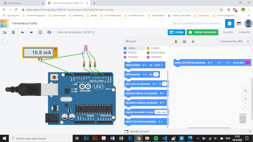
For simulate that determination power consumption I used Tinkercad. The multimeter has to be connected in the following way to determinate a RGB power consumption:
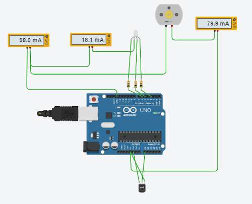
I tried with two outputs also:
Applying the folowing formula I can calculate de Power consumption of the two outputs:
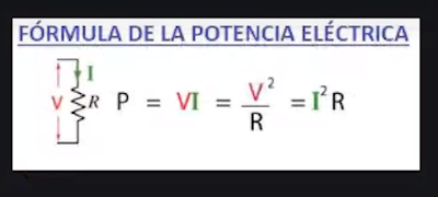
P = V*I = V^2/R = I^2 * R

Irgb = 18.1 mA
Icc= 79.9 mA

Vrgb=989 mV
Vcc =2.01V

Vrgb + Vcc = 2.99 V
Irgb + Icc = 98.0 mA

P = 2.99 * 0.098 = 0.293 W
I noticed that when I want to mesure voltage outputs turn to off.
Interfacing output devices to microcontroller
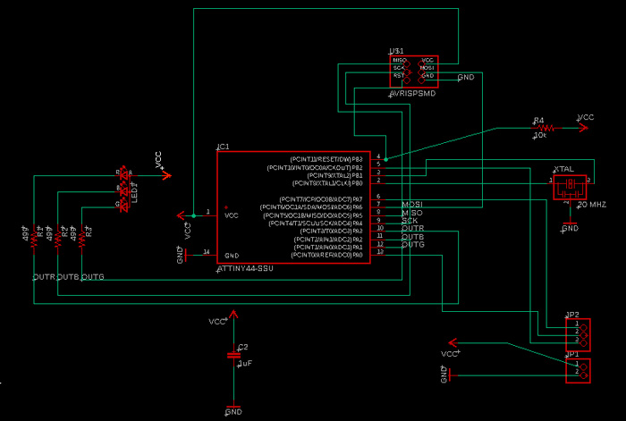
Te most important learning here was the relation between the micro-controller’s pins and the output. In my case , the outputs are a RGB and a buzzer. For this board I am usign a Attiny44 microcontroller (datasheet]) To interface an output device to this microcontroller I should use a bidirectional digital port.
Design and fabrication process
Previous design process example
Previous fabrication process example
I basically follow the same design process of the previous boards:
- Importing components in the Schematics
- Making the connections between pin’s
- Designing 15 mil lines in the BRD work table
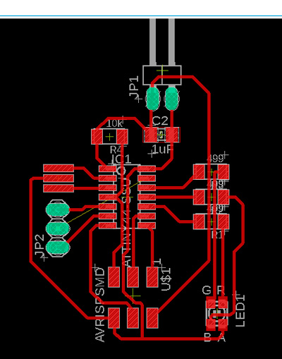
- Exporting the design as a png image

- creating a profile for the board
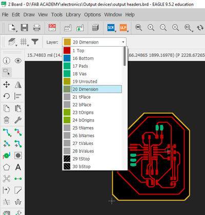
- exporting a new png image
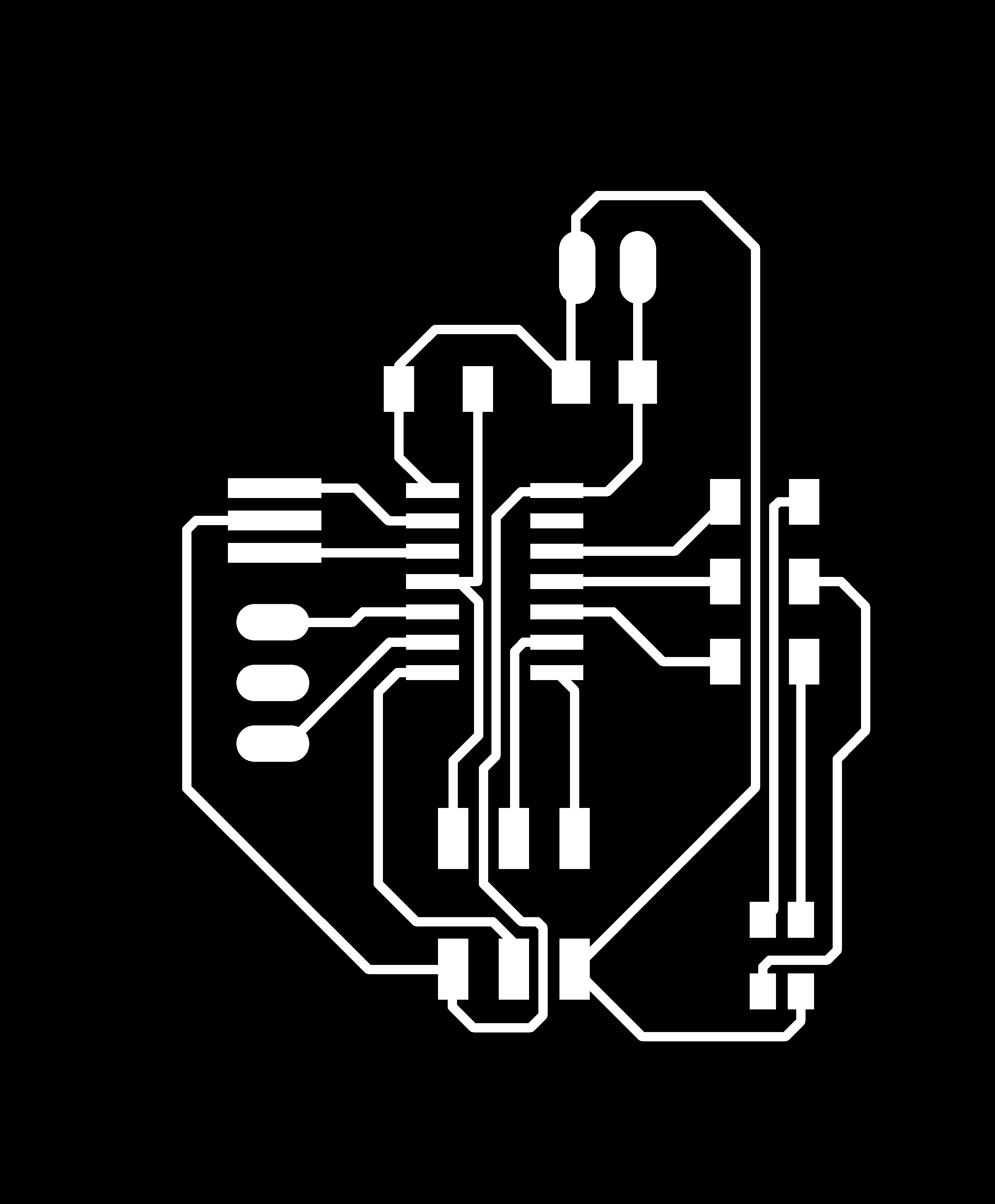
- making a full white shape of that profile

Programming process
Fist I caracterized a variable for the buzzer’s pin.
int buzzer = A0;
After I set the pins configuration and the initial state of each pin.
void setup()
{
  pinMode(3,OUTPUT);//RED
  pinMode(2,OUTPUT);//BLUE
  pinMode(1,OUTPUT);//GREEN   PIN CONFIGURATION
  pinMode(8, OUTPUT);
  pinMode(A7,OUTPUT);
  pinMode(buzzer,OUTPUT);
  digitalWrite(3,LOW);
  digitalWrite(2,LOW);
  digitalWrite(1,LOW);
  digitalWrite(8,LOW);
  digitalWrite(7,LOW);
  digitalWrite(buzzer,LOW);
}
After that I programmed the action of each pin
void loop()
{
  digitalWrite(3,HIGH);
  delay(500);
  digitalWrite(3,LOW);
  delay(500);
  digitalWrite(2,HIGH);
  delay(500);
  digitalWrite(2,LOW);
  delay(500);
  digitalWrite(1,HIGH);
  delay(500);
  digitalWrite(1,LOW);
  delay(500);
  tone(buzzer,40,500);
  noTone(buzzer);
  }
Simulations
Problems
-
I designed a first borad 1 before the pandemic for this assigment but I couldn’t fabricate it so when I wanted to make it I didn’t remendered one of the components I wanted to put as an output.
-
After that I designed a board 2 with and RGB as an output but my tutor told me it was to much simple.
-
Finally I designed the board 3 in wich I put a RGB and a buzzer.
-
I writed a program for my 2 outputs. In the simulation it worked or the rgb but not for the buzzer.
Original design files and code
Board 1 | Thermistor (No fabricated)
Board 2 | RGB (No fabricated)
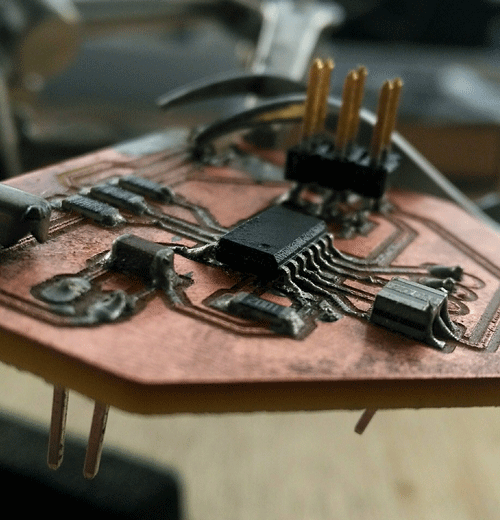
Board 3 | RGB & Headers (Fabricated)
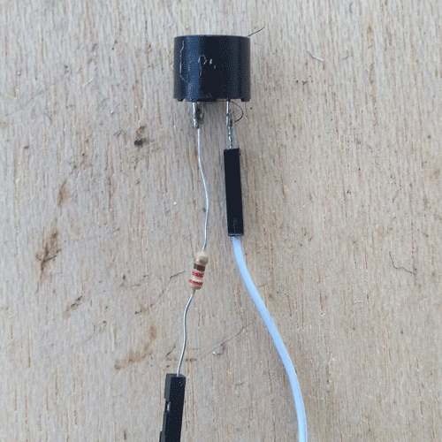
Hero shot
The buzzer need a resistor
Learning outcomes
- [x] Demonstrate workflows used in controlling an output device(s) with MCU board you have designed
Have you?
- [x]Linked to the group assignment page
- [x]Documented how you determined power consumption of an output device with your group
- [x]Documented what you learned from interfacing output device(s) to microcontroller and controlling the device(s)
- [x]Described your design and fabrication process or linked to previous examples.
- [x]Explained the programming process/es you used
- [x]Outlined problems and how you fixed them
- [x]Included original design files and code
- [x]Included a ‘hero shot/video’ of your board