
Fab Lab ZOI
Group assigment page | 2020
Computer controlled cutting
characterizing lasercutter
Work Flow
Lasercutter details
- Supra cnc
- Made in ecuador
- Pipe:60 watts
- 110V
- Chiller
Before using
- Verifying that the evacuation pipe is well located.
- Clear the laser cutter's mirrors
- Turn on the Chiller
- Turn on the ventilator
- Turn on the laser cutter
- Turn on the light
- Verify the origin location in the laser table
- Calibrate the altitude of the laser with the material that will be used
While using
- Keep the machine door closed
- Don't leave the laser cutter room while the machine is cutting
After using
- Turn off the light
- Turn off the laser cutter
- Turn of the ventilator
- Turn of the Chiller
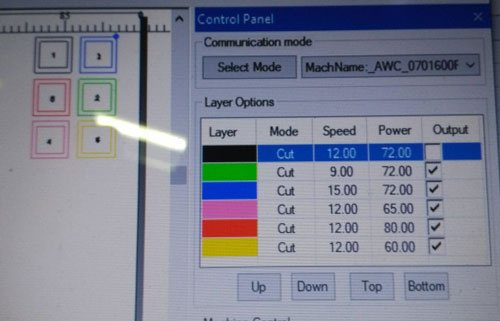
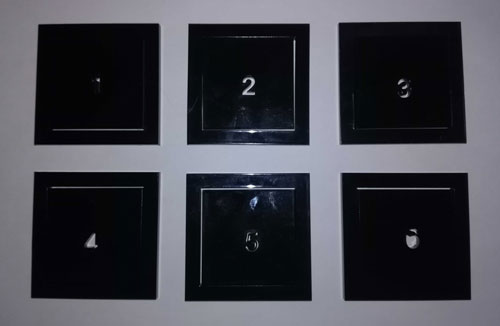
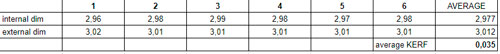
KERF
To know the kerf of the laser cutter machine we make an excercise. We Make 6 sketches of a square offsetted and we cut them with different time and power settings. I choose acrilyc 3mm for that
Conclusion
Lasercutter is a machine which can catch on fire so it's important to be attentive to it while working.
It's important to take KERF into account on our designs, especially if we want to make press fit structures
Electronics production
Design rules
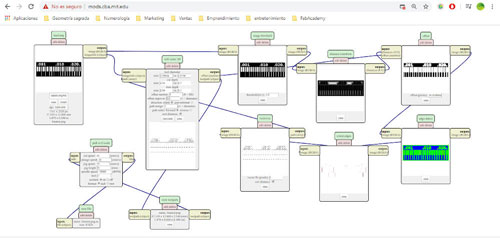
MODS
The first thing we learned was to use the MODS. I was surprised for the easly way to obtain a G-code from a png. file with this software. To do that we realized the following work-flow:
- Open MODS in the browser
- Right drag an select programs
- Then Open server program
- Go to G-code and select mill 2D png
First of all I select a png file. After that my tutor explained us how the program works and teach us about the setting.
- Tool diamater:
1/64 inches so 0.39687 mm for traces
1/32 inches so 0,79375 mm for cuttings - Cut depth:
The distance the tool will go down each offset in the Z axis util the Max depth be completed. - Max depht:
The total distance the tool will go down in de Z axis. - Offset number:
The offset number the copper board will be milled in de XY plane from the traces to outside. - Offset stepover:
Is the percentage of the milling machine cutter diameter will remove each step. - Direction:
Climb for soft materials
Conventional for hard materials. - Path merge
- Path order
- Calculate:
The button to generate the G-code from the png. file.
After that I make a line test and a cutting test with the following png files:
Those are the nc. files, I was not sure about the setting values at this first time. We reconfirm the good values the next class because we realised that the G-code format was setted in inches. We characterized settings with the folowing values:
Mill Raster 2D
- Tool diamater:
1/64 inches so 0.39687 mm for traces
1/32 inches so 0,79375 mm for cuttings - Cut depth: Almost 50% of the tool diameter.
0.1 mm for traces
0.3 mm for outlines - Max depht: The thickeness of the board
1.7 mm - Offset number: 3-5
- Offset stepover: 0.5
- Direction:Climb
- Path merge
- Path order
Path to GCode
- Cut speed: 240 mm/s
- Plunge speed: 120 mm/s
- Jog speed: 75 mm/s
- Jog height: 5 mm
- Spinfle speed: 10 000 RPM
- tool: 1
- coolant: on
- format: inch
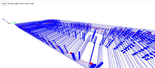
If we know enough about settings we can confirm in this toolpath visualizer if we are ok.
Tooling
We start dowloading an auto-levelling.
At that moment we already knew how to get the G-code so we learned how to add an autoleveling code to the trace G-code. The PC ask me to download a software able to open that program so I download Java
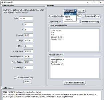
We had only to:
- Set with the LinuxCNC option
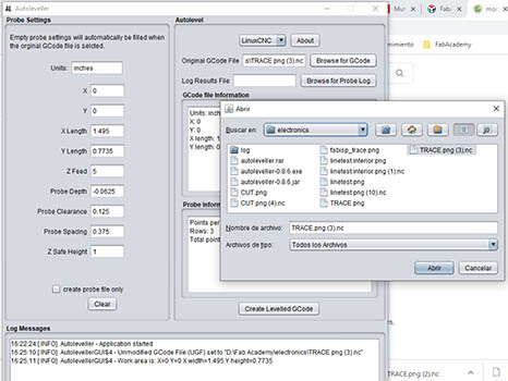
- to upload the [trace GCode](../files/w5/linetest.nc)
- Click to Create Levelled GCode
- Save the new .ngc file in a key to open it into the machine's computer.
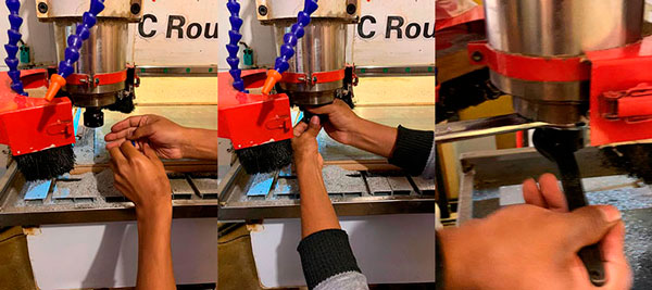
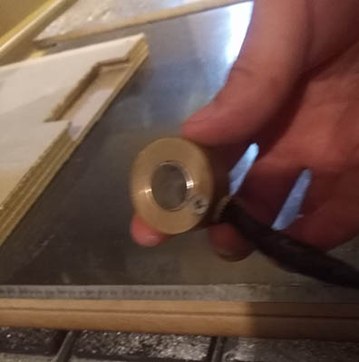
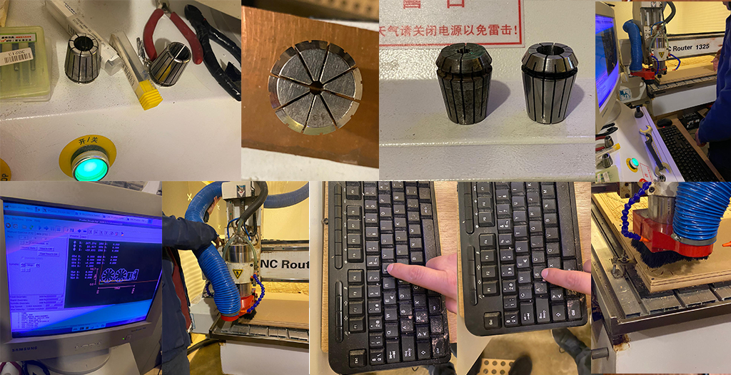
After that we came into the CNC machine's room We stick the copper board up to a piece of wood with doublesided tape. We met the 1/32 (45 degrees) and 1/64 (30 degrees) endmills:
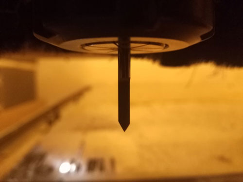
One of our tutors shows us how to install the tool. Also he tolds us the precautions we need to look at to don't hurt ourselves neither the endmill tool.
Production
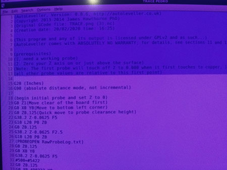
Then we opened the autolevel GCode file in the machine's PC to delete the first part of the code and save it:
After we opened that file in the CNC software:

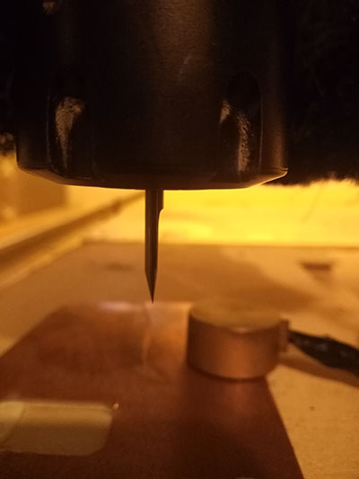
For the autolevel process we put on 0 the x and y axis and we let z axis between 1 and 2 mm on the board.
Then we put the electric sensor on the board to play the code.
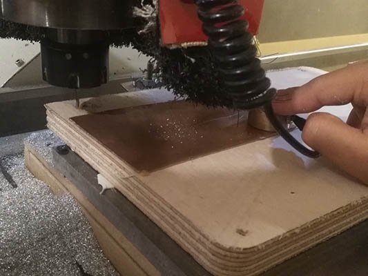
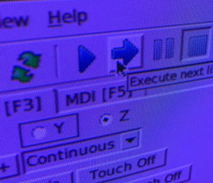
After the autolevel ran we continue running the Gcode step by step until the spindle turned on and reached a constant speed. After that we let run the entire Gcode.
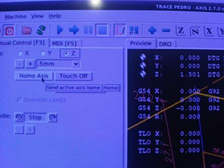
To make the cutting we changed the 1/32 sized endmill by the 1/64 one. Then we had to reset the z axis on 0, we did that by lowing the endmill by milimeter fractions with the electric sensor on the board until the following message appears on the screen:

Then we run the GCode step by step first to let the the spin reach a constant speed and then we click on play to run the whole toolpath.
HERO SHOT:
Conclusion
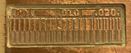
The fabrication proccess of a electronic board is not a complicate thing, there are precise step to be accomplished and if there are done correctly there is not too much possibilities to make mistakes.
The smallest thinnest line we can make with the lab's milling machine is 0.02mm.
3D Scanning and printing
3D Printing
For this class we came to MakerGroup ,
Saadin Solah's 3D printign business.
I saw 2 diferent styles of 3D pringting there was FDM printers (Ultimaker) and STL's (FormLabs)
We donwload a [test](../files/w6/test3d.stl) in Thingiverse to test the design rules of our 3D printers.
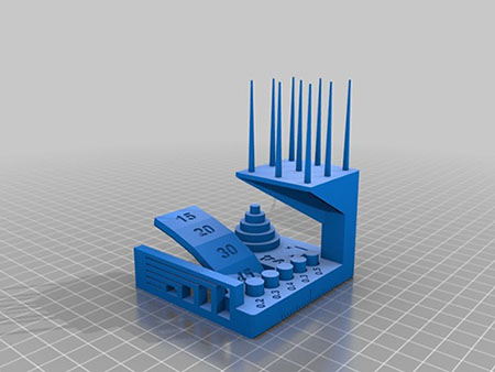
- Open the STL file in CURA
- Select a 3dprinter
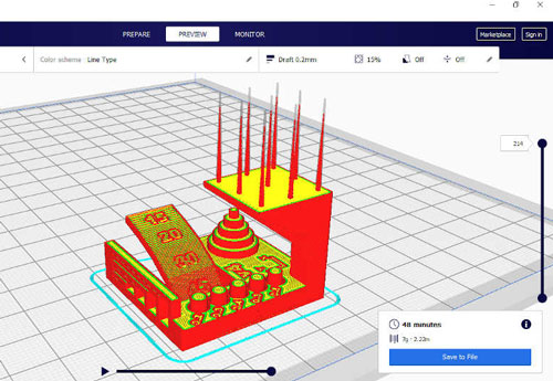
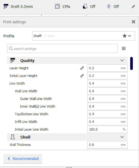
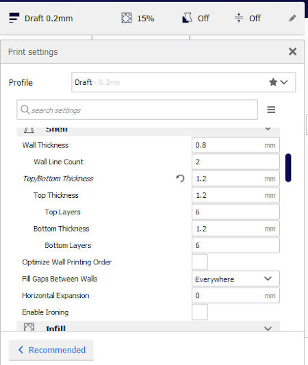
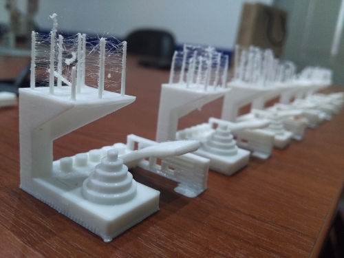
Then we make the settings with the values our tutor gave us. We didn't put any supports because the aidea of the exercice was testing the printers capacity in terms of precision and vertical printing capacities.
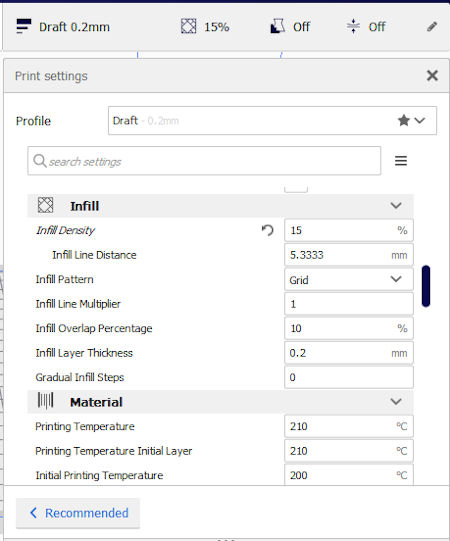
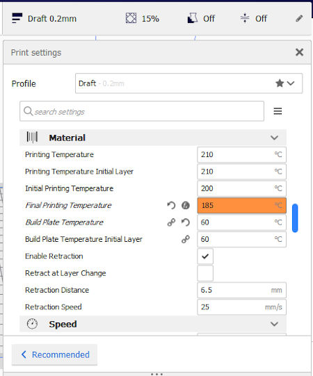
Finally we print some those test in diferent printers.
3D Scanning
I was really not familiarized with 3D scanning and found that really usefull and fun.
We make a scan of downloadable here.After that we opened the file in CURA
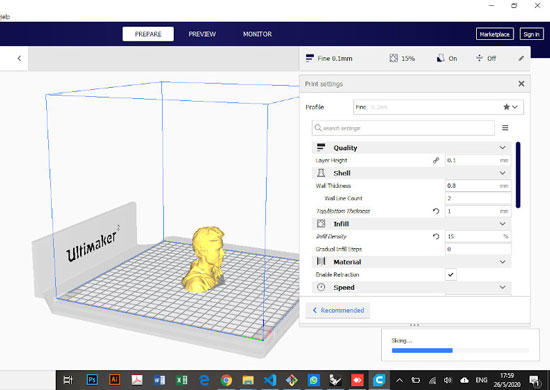
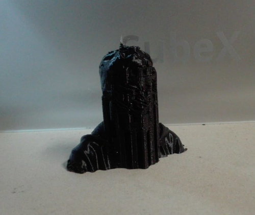
We did not print our scannings but during the confination my lab enabled a system to use the machines in a remote way. So I took the opportunity to print my 3d Scanning.
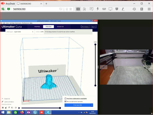
So here the remote 3D printing process:
- Download Anydesk
- Open the program and follow the steps of the manual downloadble here
- Copy the stl file to the linked desktop
- Open CURA in that pc and open the file to print
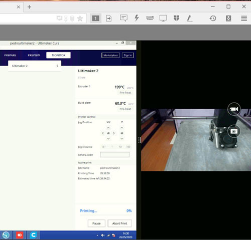
- Click onto print via USB
- Pre-heat the extruder and the plate if you upload a GCode file
- Put on 0 the x,y, and z axes. -
- Wait the temperature reach the settings values -
- Print!
 -
- 
Computer-Controlled Machining
Group assignment
Document your work
Roberto Moya's pageTest runout, alignment, speeds, feeds, and toolpaths for your machine
Test runout, alignment, speeds, feeds, and toolpaths for your machine Machine:CNC Router 1325 in the Fab Lab ZOI, bed size 1220 x 2440 mm.
CNC RULES to use LINK
1. Do not leave the room while it is on, at least one person should be in the room at all times observing the machine when it is running.
2. Do not put your hand or any other part of your body any closer than 6 inches to the bit when it is moving. The router will not stop and can cause severe damage.
3. If the bit breaks or something seems to be broken or misbehaving, hit the pause button on the computer screen. If it needs to be shut off immediately press the red emergency stop button on the front of the bed.
4. Make sure no screws are on the path of the router. The screw will break the bit and will normally stay embedded into the project, but is capable of flying off and hitting someone.
5. After use of the machine clean the floor and all of your excess material out of the room, the sawdust on the floor and scraps can be hazardous and cause an injury.
6. Leave the CNC room clean and the way it was when you began your project. The CNC tech is not responsible for cleaning.
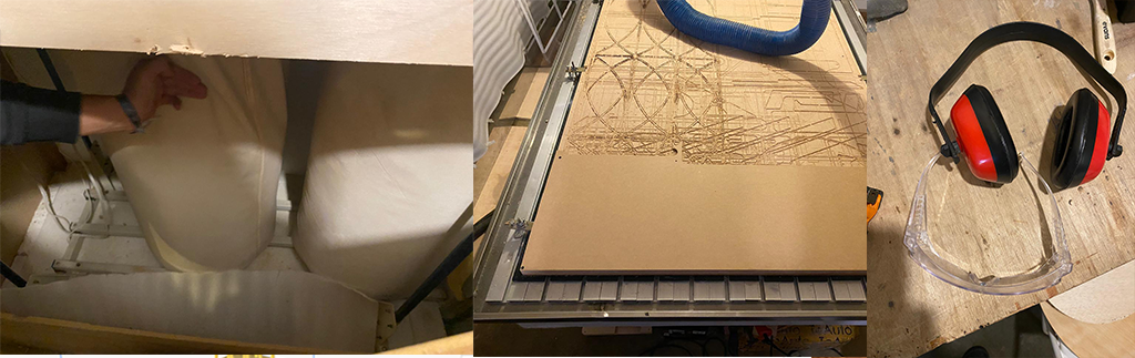
7. Check and empty the vacuum bag frequently. When you are complete with your project empty the vacuum. The CNC tech is not responsible for emptying.
8. Use hearing protection while the CNC is running.
9. Wear protective safety glasses when the CNC is running.
10. Do not disconnect the main vacuum line of the CNC if you wish to clean excess dust off of the work. Instead, use the smaller portable vacuum in the shop.
11. There will be no milling or machining between the hours of 11 p.m. and 8 a.m. Just like working in the shop with other power tools, you need to be rested and focused on the CNC process.
Polyester resin process
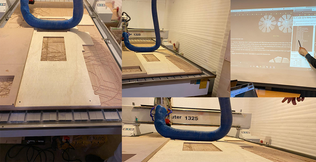
Guide to use the CNC router machine LINK
a) Activate the ignition switch
b) We turn on the computer that controls the CNC
c) We turn on the CNC, green button
d) Verify that the cooling pump is working.
e) Turn on the extractor
f) The CNC does not save the zero position in a memory, so you have to reconfigure the zero of the machine.
g) We open the Linux CNC software and move the machine, with the arrow keys we can move to the right, left, forward, back and with the keys (repag) up and (avpag) down, in this way we control the axes
x , and and z.
Alex page
Moulding and Casting
Group assignment
Roberto Moya's pageReview the safety data sheets for each of your molding and casting materials
Safety in the process
- First you must find an open space with ventilation.
- You must wear safety glasses to protect your eyes against irritation.
- Wear gloves, to protect your hand´s skin from the elements you are going to combine.
- Wear mask, first of all becuase of COVID and also it is going to protect your health.
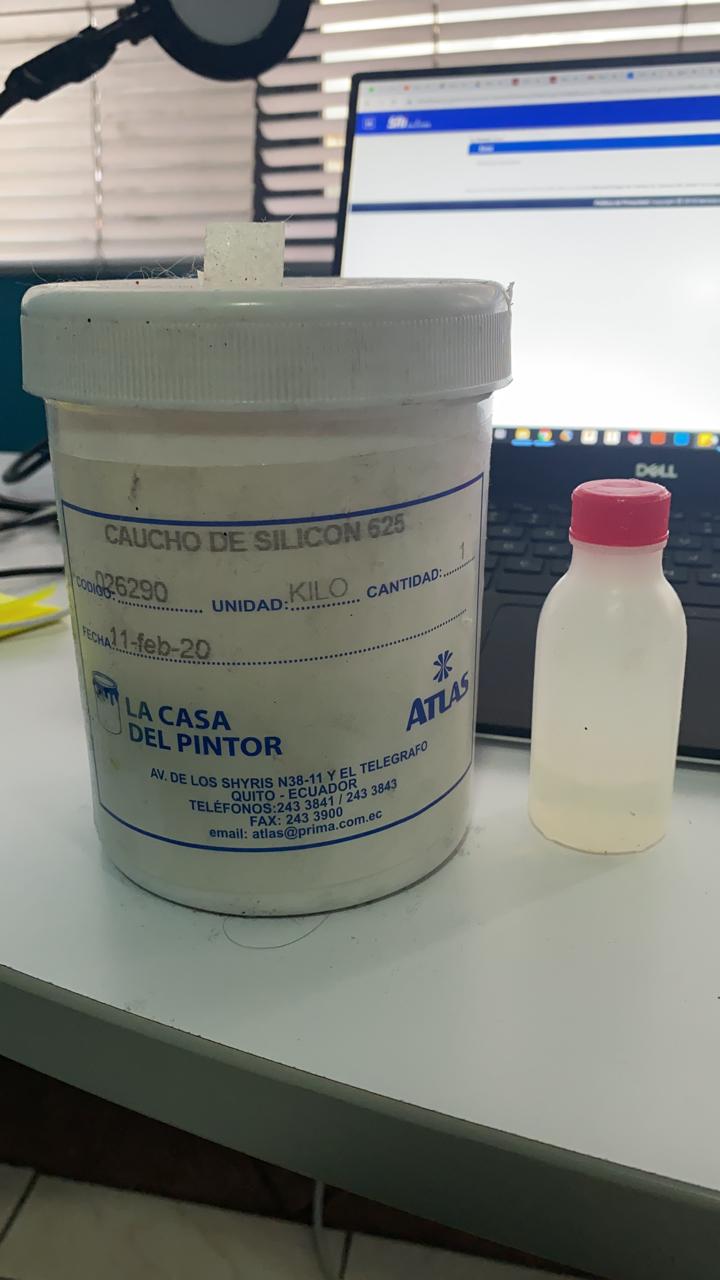
- Materials of Silicone rubber (component A) / Catalyst (component B):
- Rubber silicone (Component A): it has to be combine with the catalyst (component B).
- Catalyst (Component B): Thixotropic additive for addition cure silicone, it has to be combine with Component A, proportion: 1 and 5%.
- Vaseline: to make easy the process of take of the material.
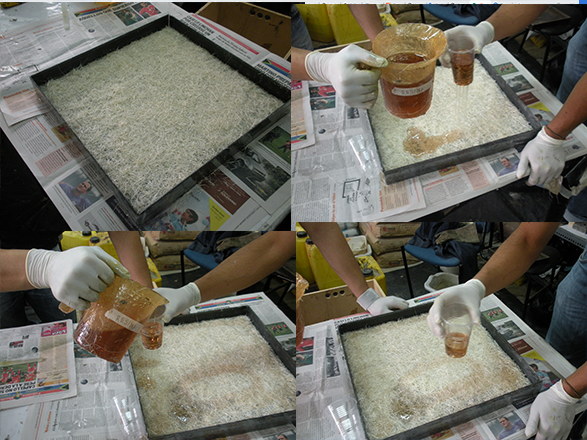
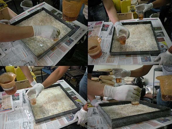
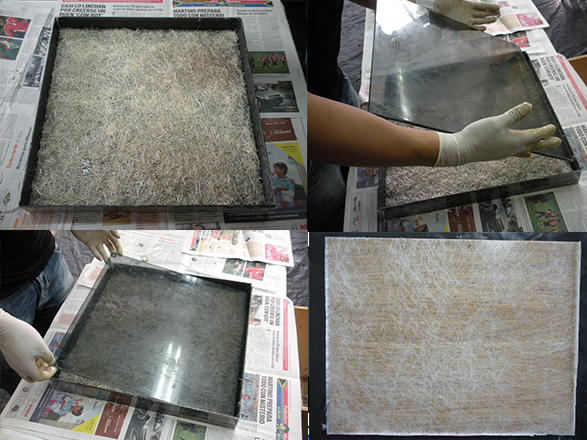
Polyester resin process
Machine Design
Individual Assigment
Pedro Almeida's pageMechanical design
For this assigment we decided to tranform a CUBEX 3d printing machine into a 5 axis milling machine.

We took an exisiting 4 and 5 axis mechanism as an example to model our machine. And we choose to put each motor just on the axis.

So in one week we designed in 3d the 4th and 5th axis adaptation to our 3d printing machine. We helped our selfs with a 3d model of one of the motors we had (dowloadable here)
First I make the design itself in Rhino, thinking essentialy at the mechanism. After that Roberto improved the design in SolidWorks.
 Download 1st Design file

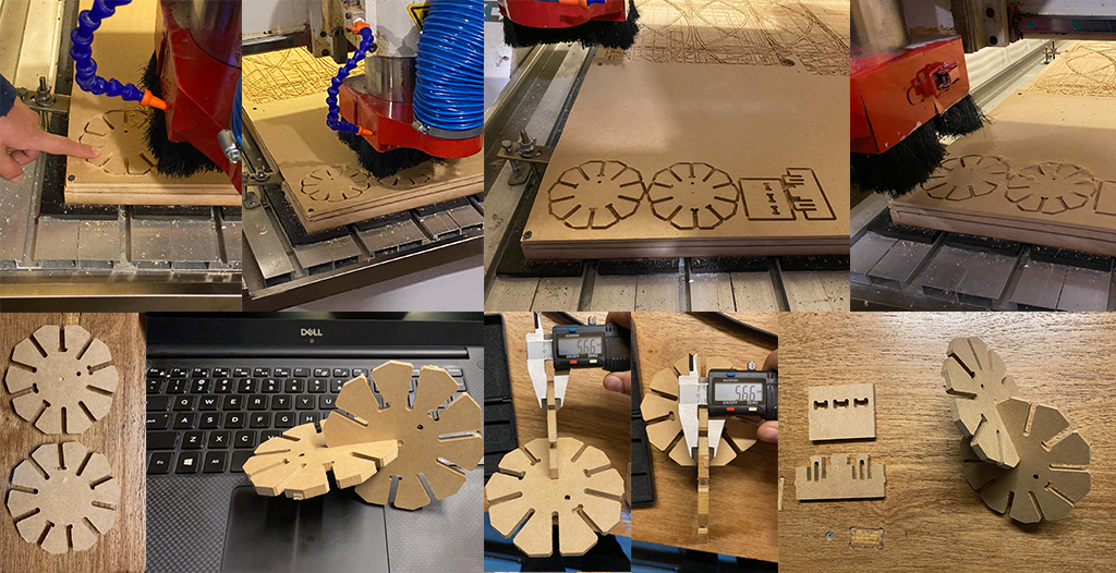
At that moment we already had the 2D plans to cut MDF boards in the laser machine:
But there was an error about the thikness of the material. We thought there was 5mm thikness MDF available in the lab but there was 6mm, so we were pushed to change the design. We take the oportunity to duplicate each part of the machine to make sure it doesn't bend
We considered that this design will be to hard to make so we decided to redesign the machine structure

We added some finger joints, designed the axis A for the motor axis fit perfeclty in it and modeled two assemblies to print them in 3D.
After that we cut the MDF (6mm) boards in the laser machine with power 70% and speed 8mm/s first. After we change the speed to 10.

 Click on Origin
Click on Download
To be sure that the cutting will be made correctly, click onto the Run Box.
Finally click on Startto run the machine.
Click on Origin
Click on Download
To be sure that the cutting will be made correctly, click onto the Run Box.
Finally click on Startto run the machine.
The pieces were correctly cutted.
 But the fingerjoints didn't fit correctly so we used glue and screws to join the parts.
 The previous picture shows the structure without the 3D printed pieces. Those parts where printed remotely.
 Unfortunately the holes to fit the motor axis and to pass de the screws were to small and we had to sand them.
 After that we proceed to join them to the machine.

Electronics
For this part we have to know the motors we are usign, their voltage and current references and the drivers we'll use to make them work. This will be a 5 axis machine so we'll use a CNC shield too.

M42STH47-1584SC-S
Voltage max= 2.8 V
Current max= 1.68 A
Driver: DRV8825
 The previous formula allows us to find the value to calibrate the driver, so:
Vref=Imax*5*Rsense
Vref=1.68*5*0.1
Vref=0.84V
but we want the driver works at 70% of its capacity so:
Vref*0.7=0.58V
With this value now we can calibrate our driver using this tutorial
Once the machine was assembled with the step motor We proceed to connect the drivers and the motors to the the CNC sheild following schematics.

 We connected the cncshield to an Arduino mega using 2 pins per driver, one for step and the other for direction.
The last thing we do before charging the code was to connect the current for the motor. For that we use an adaptation between a laptop charger and a wire. We hed to identify the positive and the negative wire, for that we use the voltmeter.
We connected the cncshield to an Arduino mega using 2 pins per driver, one for step and the other for direction.
The last thing we do before charging the code was to connect the current for the motor. For that we use an adaptation between a laptop charger and a wire. We hed to identify the positive and the negative wire, for that we use the voltmeter.


Programming
We search a code exaple for driver DRV8825 in the web to make a first moving test with the steppers. We took DRV8825">this one. We modified the pin configuration to the Arduino pins we were using and ten we charge the code in the ArduinoMega.
The first was a 100 steps program. After I play changing the steps, acceleration and speed values. Finally a modified the code to move both steppers at the same time.gsgd
Vehicula ultrices sed ultricies condimentum. Magna sed etiam consequat, et lorem adipiscing sed nulla. Volutpat nisl et tempus et dolor libero, feugiat magna tempus, sed et lorem adipiscing.
Ultrices erat magna sed condimentum
Integer mollis egestas nam maximus erat id euismod egestas. Pellentesque sapien ac quam. Lorem ipsum dolor sit nullam.
Erat aliquam
Vehicula ultrices dolor amet ultricies et condimentum. Magna sed etiam consequat, et lorem adipiscing sed dolor sit amet, consectetur amet do eiusmod tempor incididunt ipsum suspendisse ultrices gravida.


Nisl consequat
Aenean ornare velit lacus, ac varius enim ullamcorper eu. Proin aliquam sed facilisis ante interdum congue. Integer mollis, nisl amet convallis, porttitor magna ullamcorper, amet mauris. Ut magna finibus nisi nec lacinia ipsum maximus.


Lorem gravida
Proin aliquam facilisis ante interdum. Sed nulla amet lorem feugiat tempus aenean ornare velit lacus, ac varius sed enim lorem ullamcorper dolore. ac varius enim lorem ullamcorper dolore. Proin aliquam facilisis.


Duis sed adpiscing veroeros amet
Proin tempus feugiat sed varius enim lorem ullamcorper dolore aliquam aenean ornare velit lacus, ac varius enim lorem ullamcorper dolore.
Get in touch
Auctor commodo interdum et malesuada fames ac ante ipsum primis in faucibus. Pellentesque venenatis dolor imperdiet dolor mattis sagittis.
© Untitled. All rights reserved. Design: HTML5 UP.