COMPUTER-CONTROLLED MACHINING
Group assignment
Test runout, alignment, speeds, feeds, and toolpaths for your machine
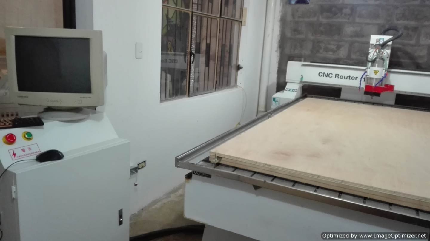
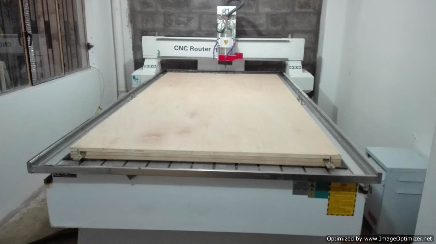
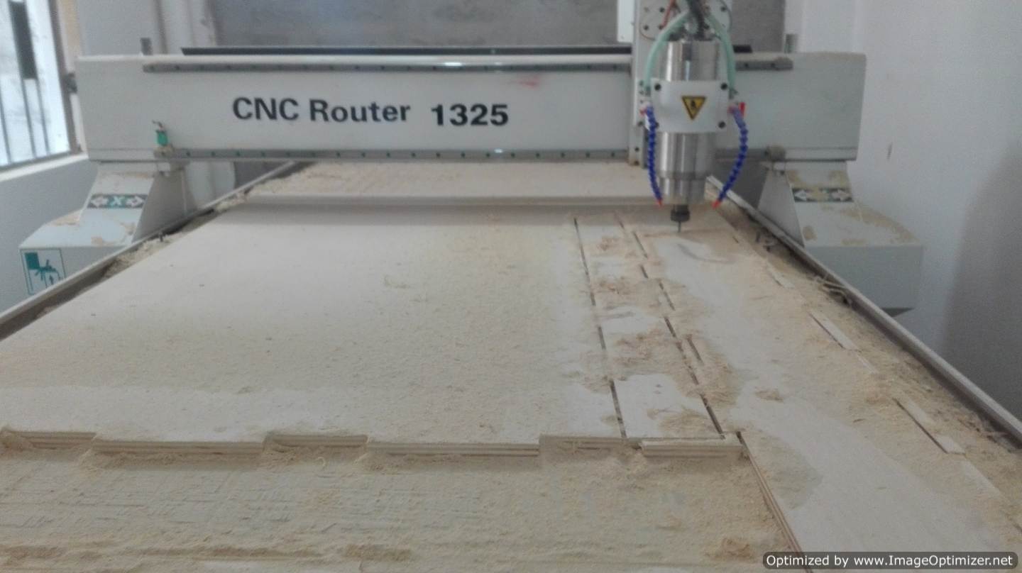
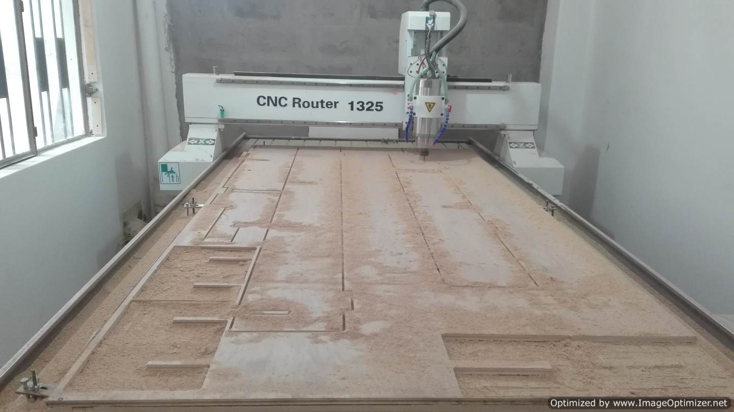
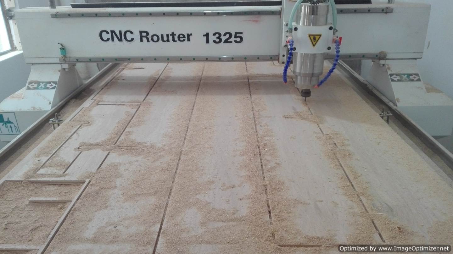
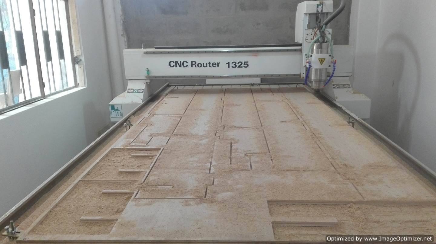
The Materials, tools and software: CNC Roter 1325 (Tools), Wood (Materials), Rhinoceros (Software) and Linux CNC (Software). In the Fab Lab ZOI uses a CNC router Router 1325 and has a dimension of 1220 to 2440 mm. with the assignment of the group a test was made for the machine.
SAFETY RULES FOR THE CNC
In the web search the ideal rules of the cnc machine; this information is property of Architecture Department School of Architecture & Design of The University of Kansas
How to use the Router CNC
The Guide is very useful for people who started in the world of cnc.
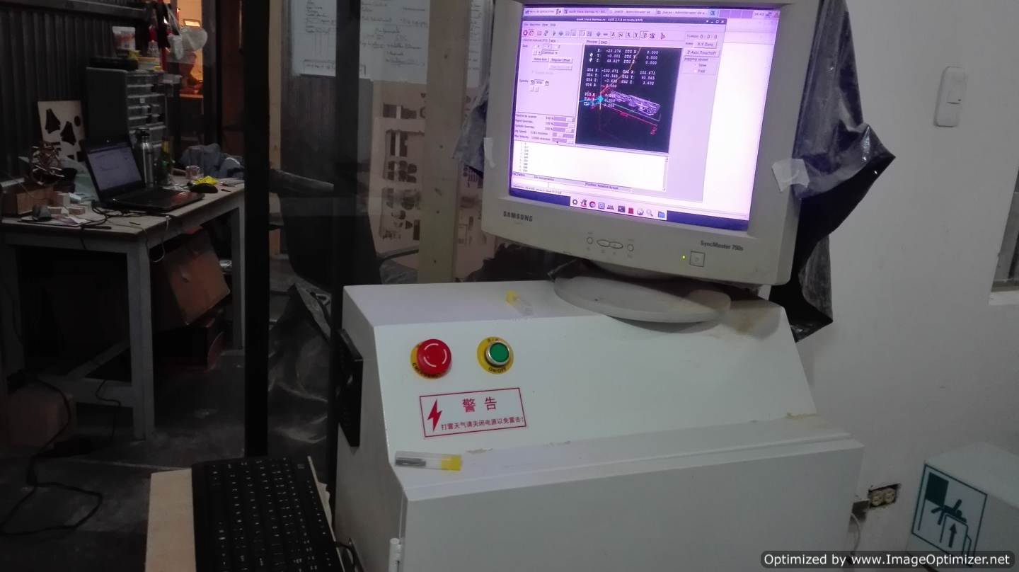
* Activate the ignition switch
* We turn on the computer that controls the CNC
* We turn on the CNC, green button
* Verify that the cooling pump is working.
* Turn on the extractor
* The CNC does not save the zero position in a memory, so you have to reconfigure the zero of the machine.
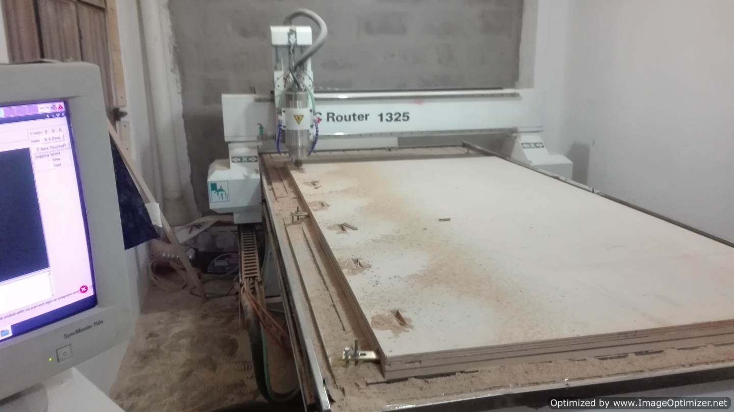
* We open the Linux CNC software and move the machine, with the arrow keys we can move to the right, left, forward, back and with the keys (repag) up and (avpag) down, in this way we control the axes x , and and z
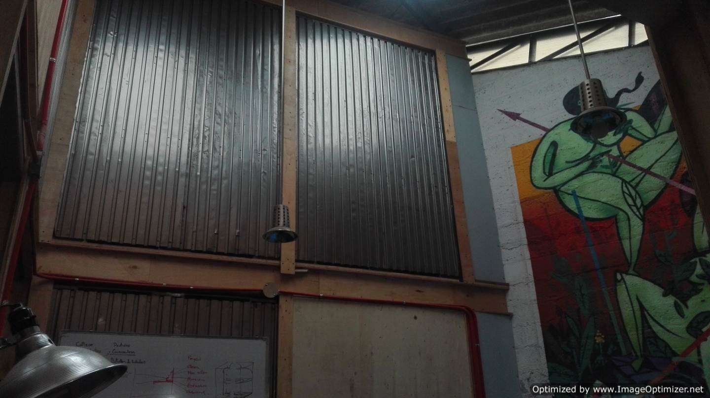
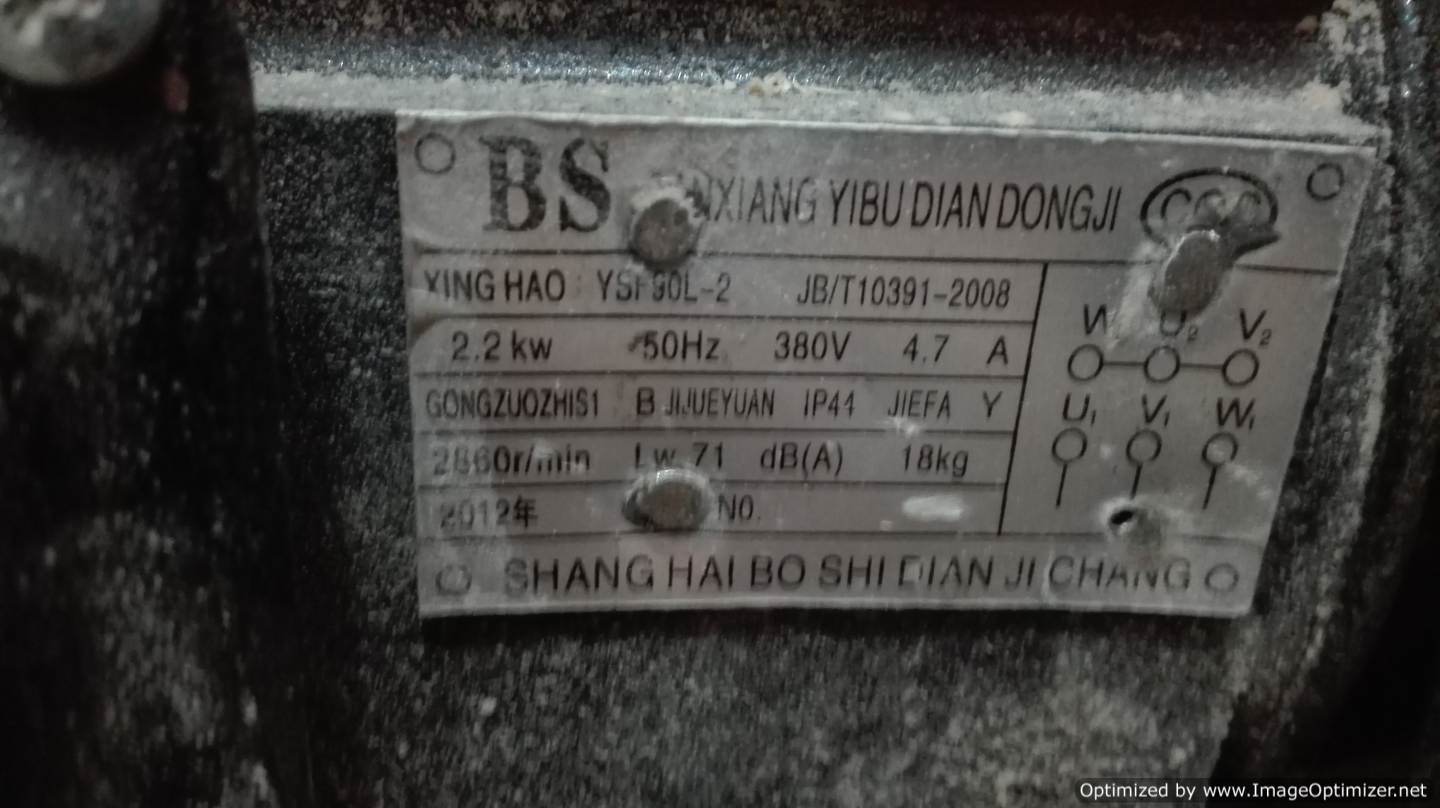 We have a severe problem in the FAB-LAB with the extractor, the normal voltage that we have in the electric network in Latin America is 110v or 220 V at 60hz, what is the problem? Well, the working motor of the extractor is from 380 V to 50 Hz, in the FAB-LAB we only have 220v maximum. I have read in several documents that you can connect a motor 380V with 220 V network through a series of components, I do not know how effective this is and how much this affects the engine and even how to do it if someone reads this would be very grateful in help me with a solution. I attach the characteristics of the engine
How to place a new material, hold it and work on this material?
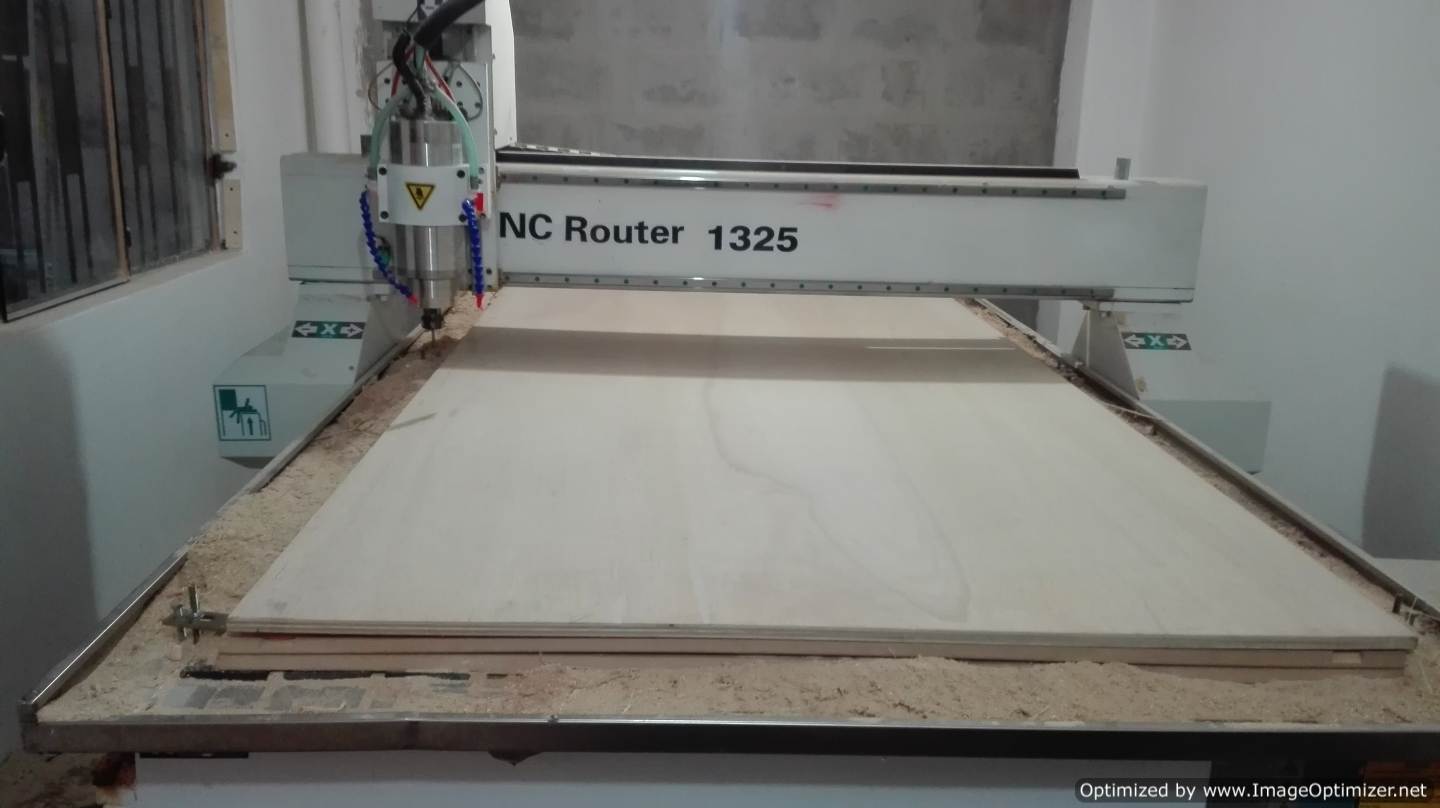 1.- We place the material on the work table, as a recommendation we move the z-axis a little upwards to avoid hitting it, in the same way we move the head towards the back.
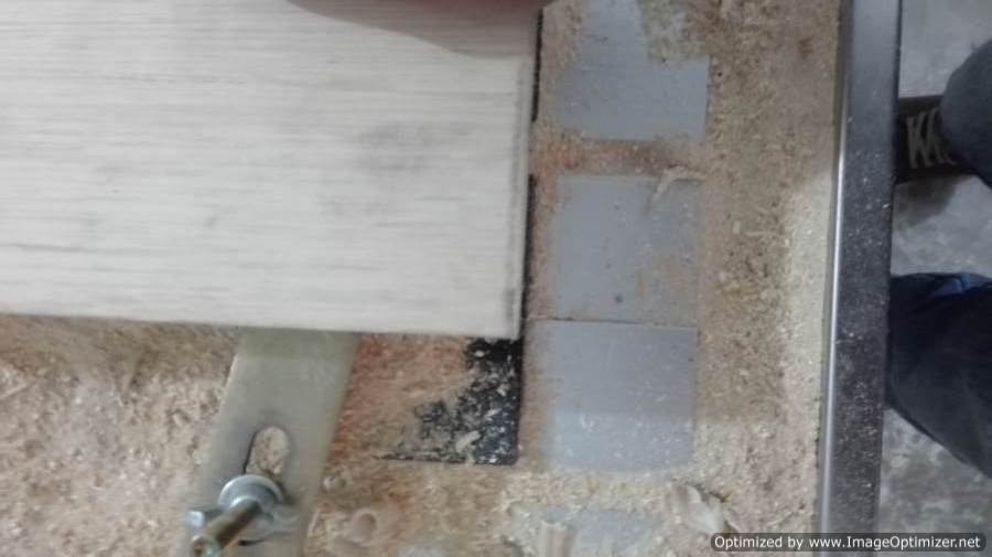
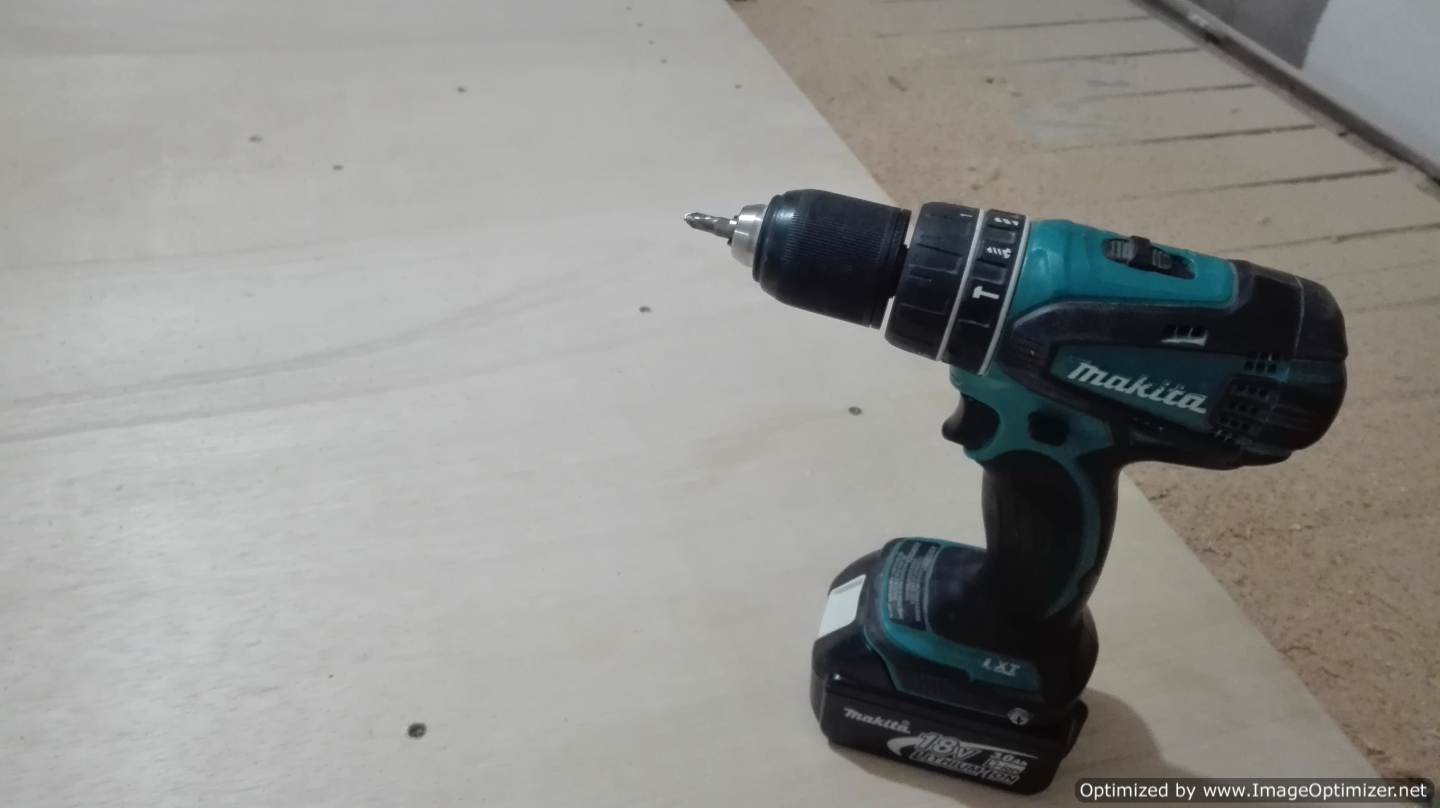
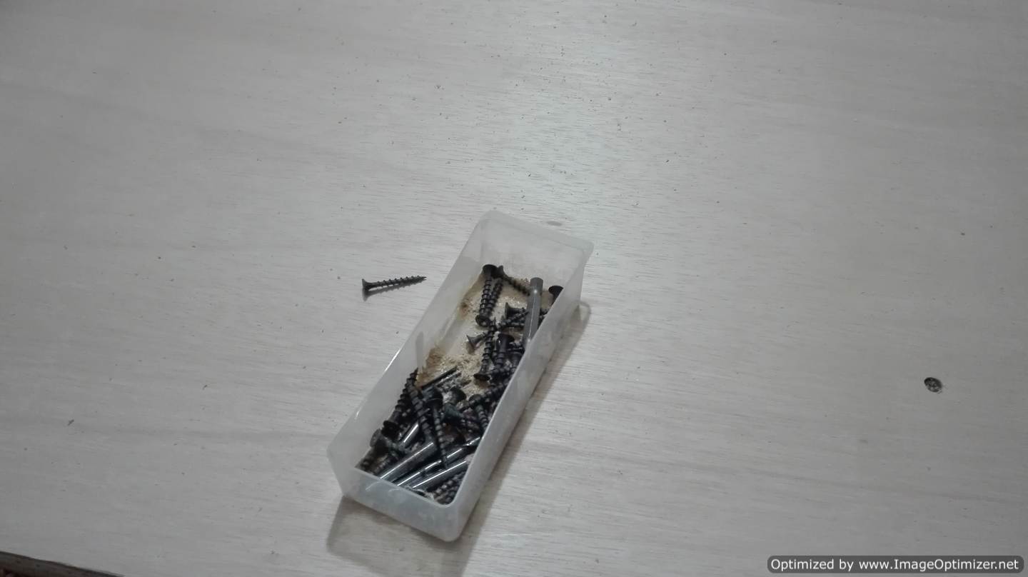
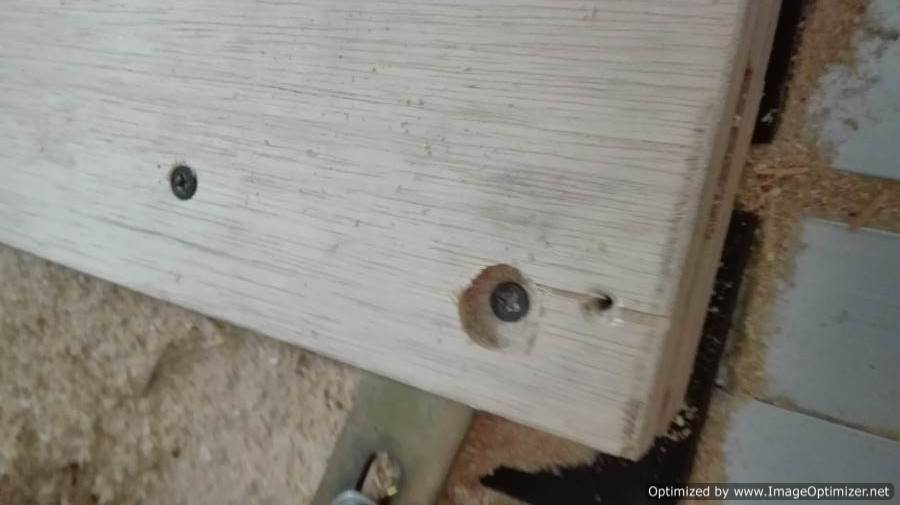
2.- Joining the new material to the table is a very complicated but fun job, there are 2 ways to do it, one is by means of some pieces of metal prying with some screws, it is good, but there is a risk of hitting the drill and break it, the second option is to fasten the material directly to the table with screws, with the help of a screwdriver and some screws will be very fast.

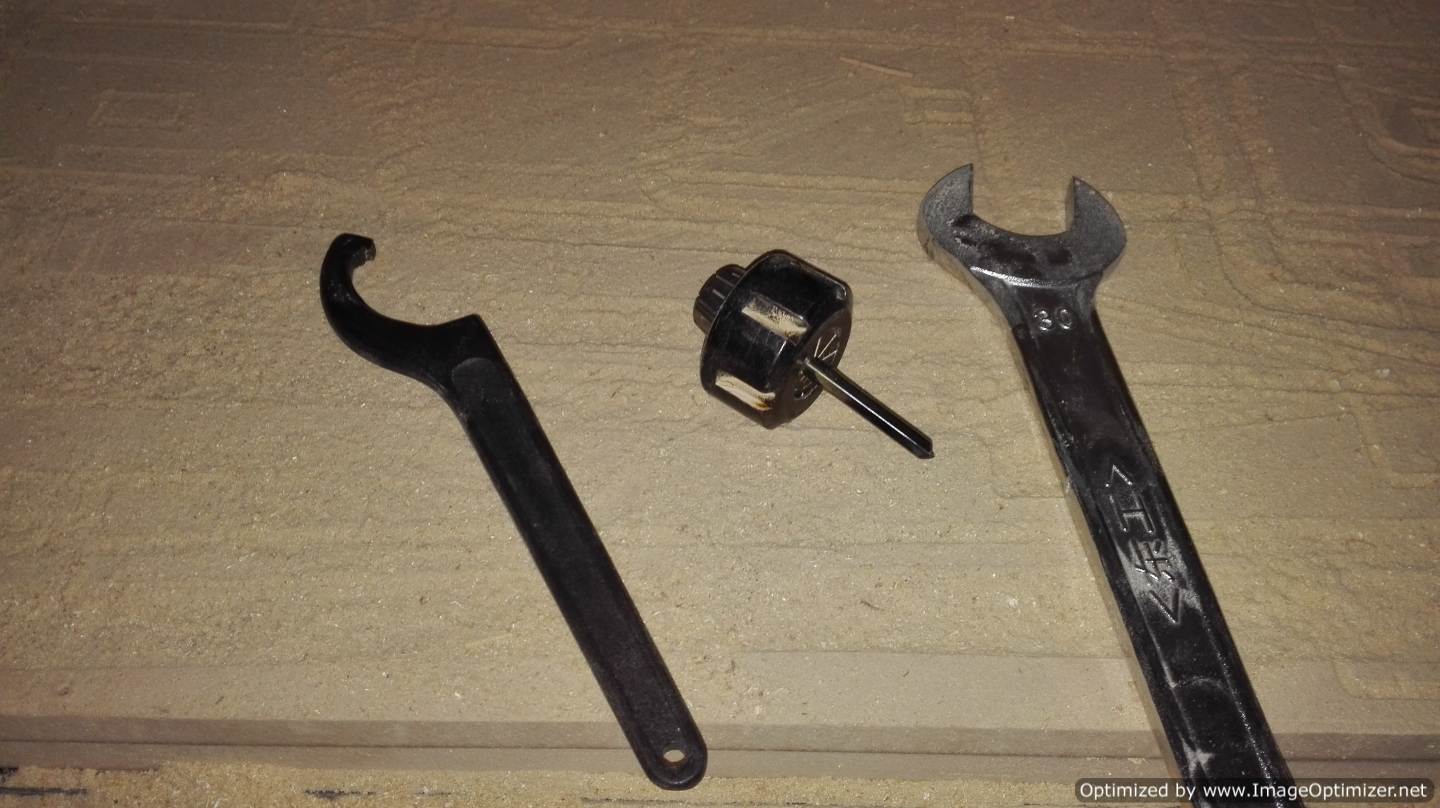 3.- Change the work tool, in this case the milling cutter, we bring the head to the front and with the tools that we provide, we make the change of the milling cutter that more convenient, we must be careful when adjusting it, a bad adjustment can make that the milling breaks in the process of work.
 4.-After placing the cutter now we are going to configure the zero part, what is the zero part?, This means where the working process of our cutting begins, it is very different from the zero machine, the zero machine is the points limit in x, y and z.
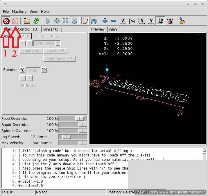
We open the LINUX CNC software, by default, we start in the following way, we click on the buttons to activate the CNC and we start to move it, the arrows on the computer keyboard allow us to move forward and backward, move from left to right, the repag and avpag key from top to bottom.
We move the machine until we reach the left front corner, we assure that it is the closest, we define the home in x, home in y and home in z. If the values shown on the screen are not 0, we press the regular offseet button and accept.
When I finish doing all this I already have the machine completely located in its zero position.
I establish tolerance, for this case I use a test file that Guillermo Guerra. did and I modify it to my needs
In this part, perform a fitting test to establish tolerance. The piece in which we can make tests of the current operation as a whole. The file is designed in 2D with basic tools, places spaces based on the thickness of the material to be used, a recommendation of Neil was to place chamfers in the entrances of the material, dog bones, this name sounds funny, but very useful in systems of lace and furniture construction. The software I use for the design is Rhinoceros, as I mentioned, based on a template created by Guillermo Guerra.
With the previous test I verify how the design and configuration programs of the CNC work, the formats accepted by the ArtCAm softeware.
Now I modify the file and create a new one, I generate the files in Artcam, now I do it faster, after making the configurations in ArtCam I generate the file in G-code, it is very strange the format that the CNC receives is .tap but it works all right.
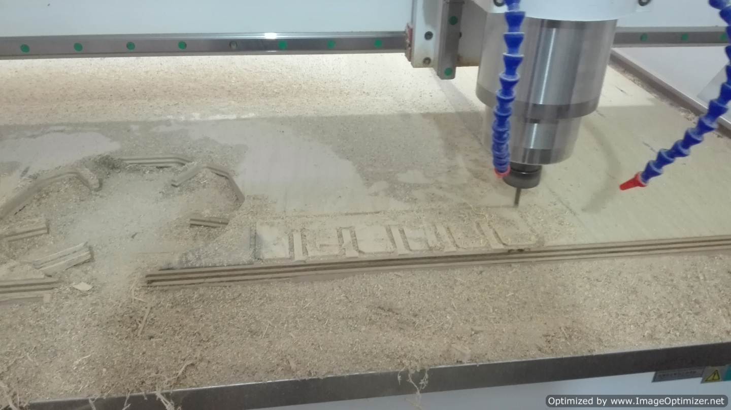
To mill the generated file, we verify the zero in x, y and z load the file and press the icon in the form of an arrow to the right to go step by step until we hear that the motor has reached the speed indicated by the code G.
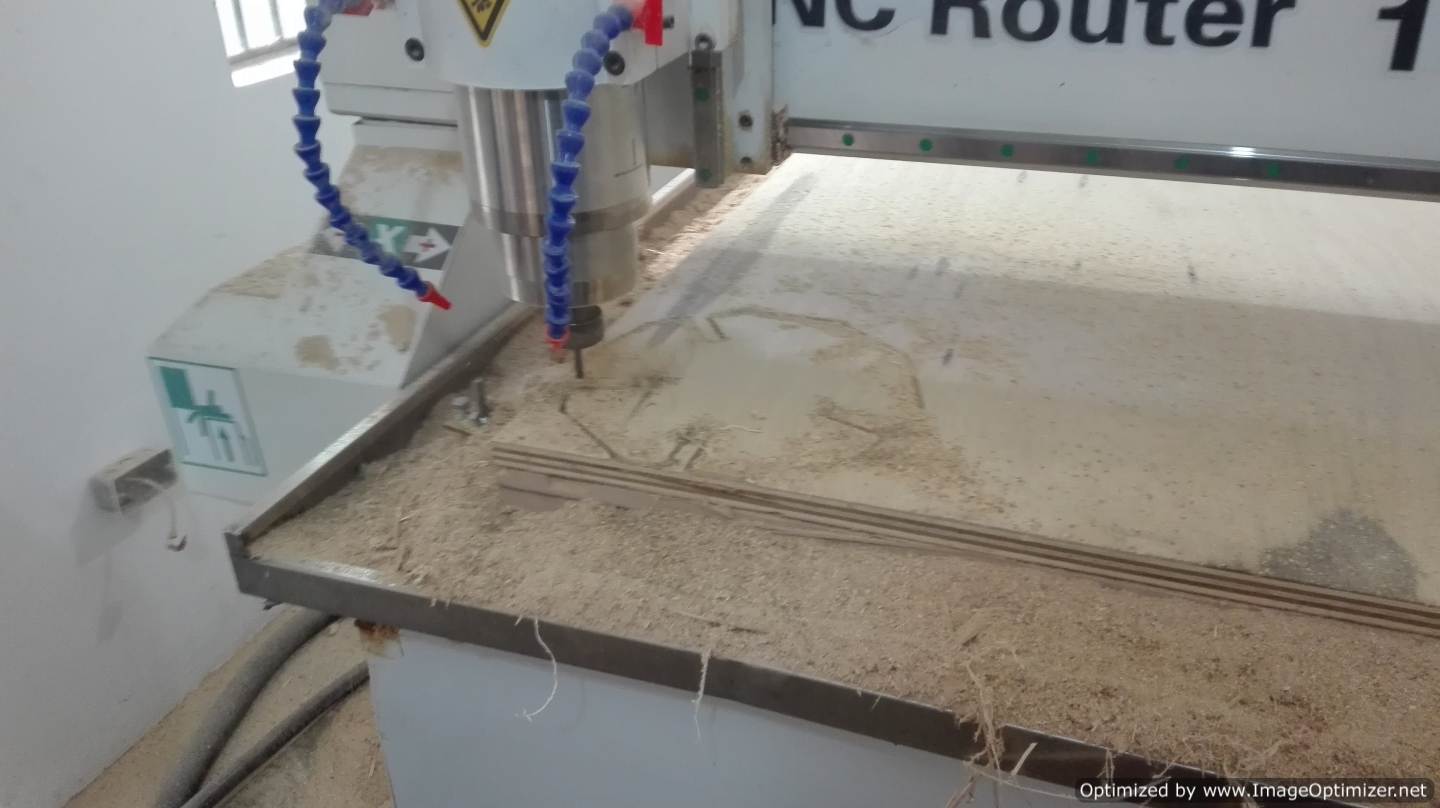
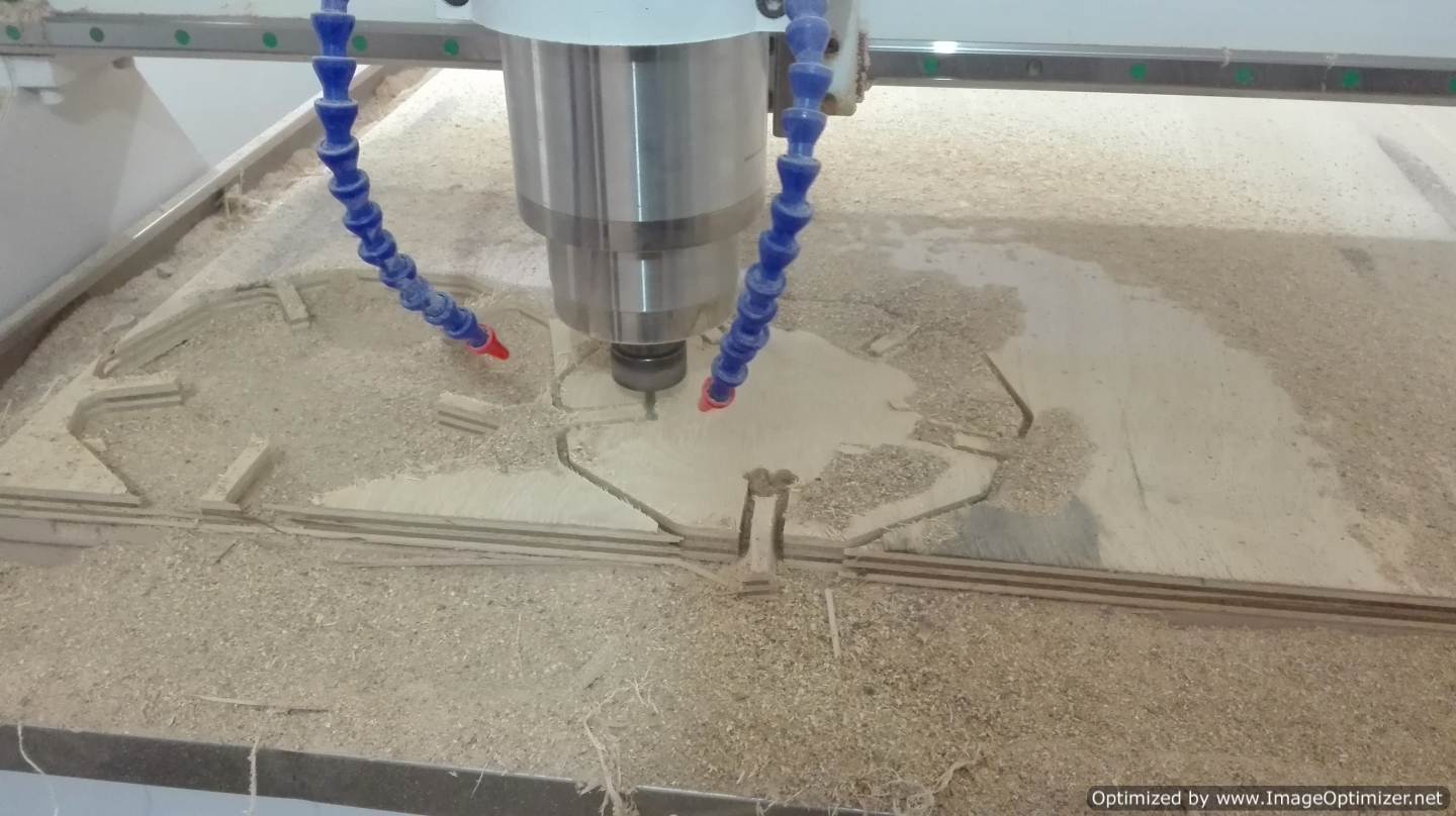
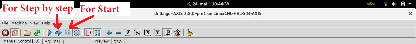 After this I press the button in the form of a pause and the machine will start with the work as shown in the images, we must be very careful in holding the pieces, they can move
.png)
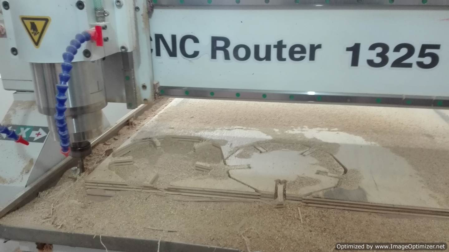
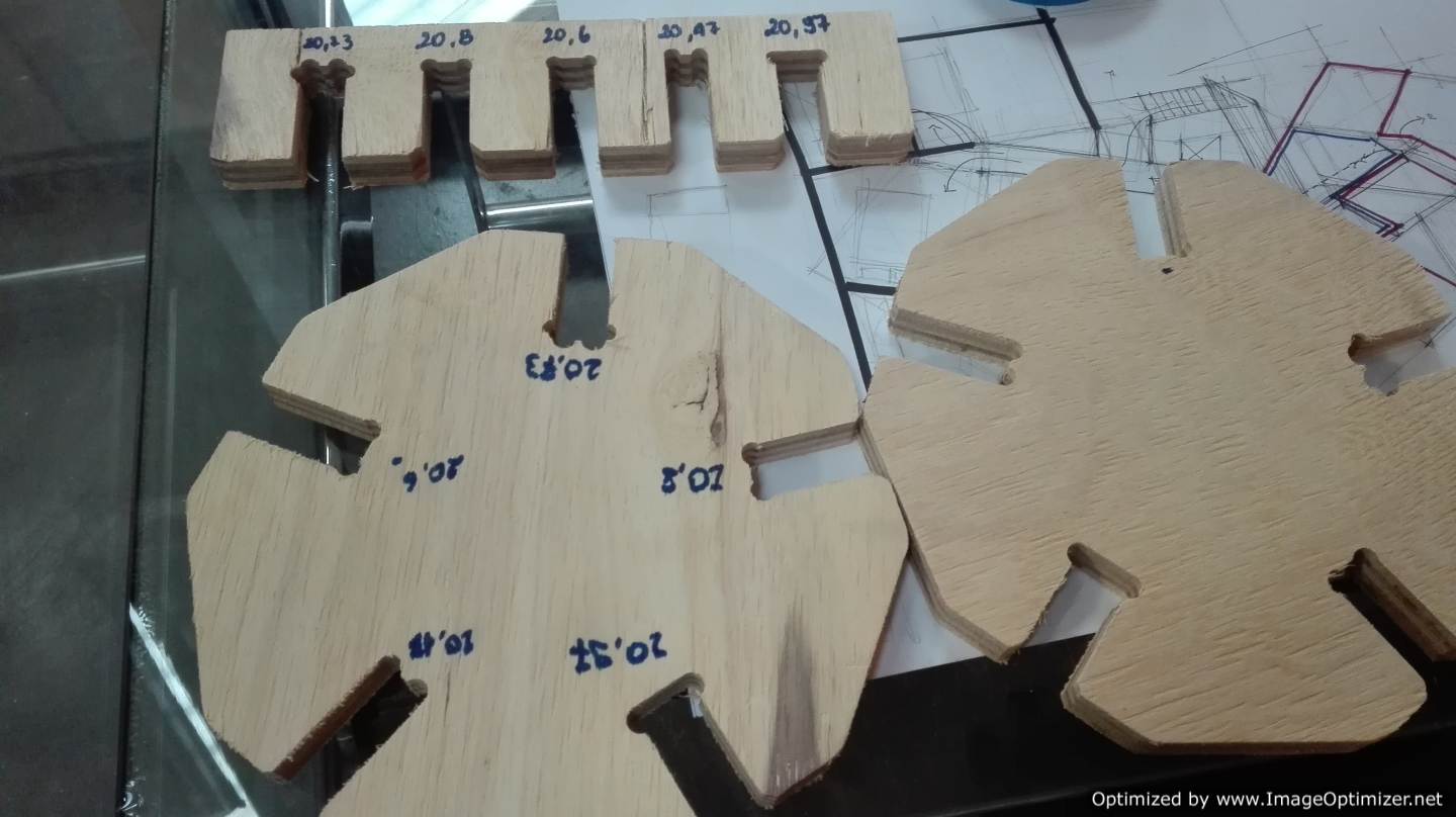
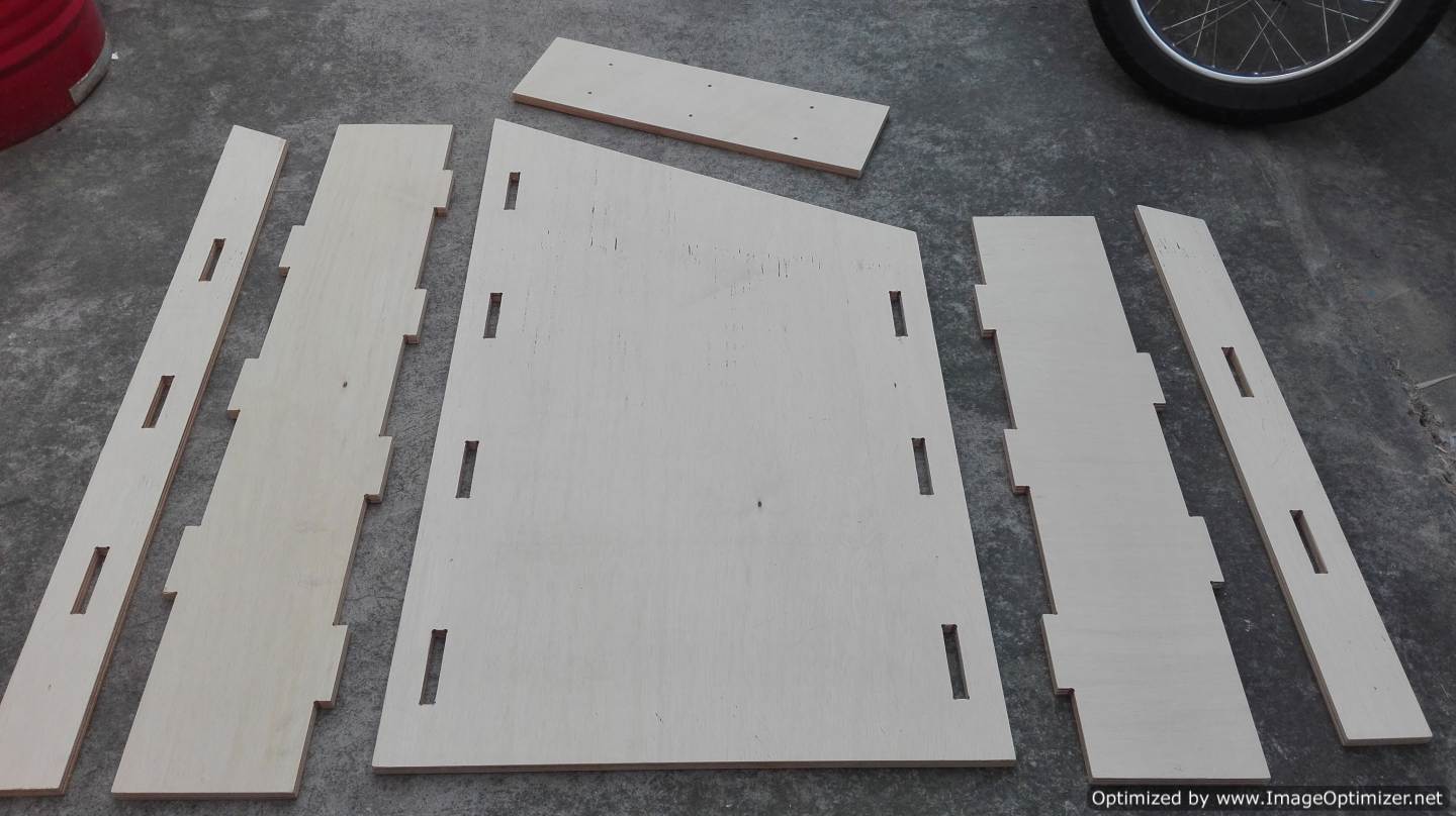
After doing the milling and removing the pieces we proceed to perform the fitting test, we take into account that the material is 20 mm, the result of the test is 20.6 mm, With this test we can proceed to design the prototype, either a piece of furniture or something big, the idea of the assignment.
I leave something extra the configuration of the milling that we are going to use
.png)
.png)
Individual assignment
Make something big
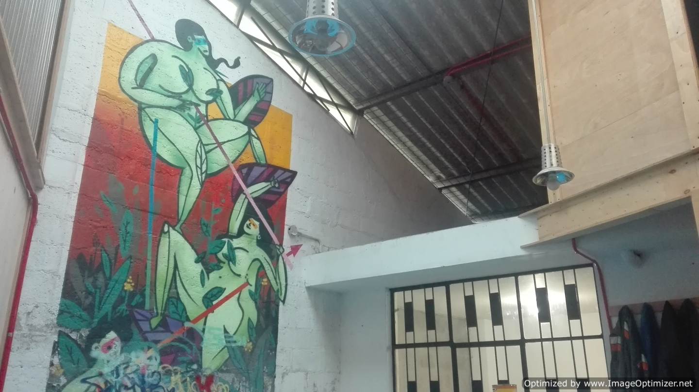
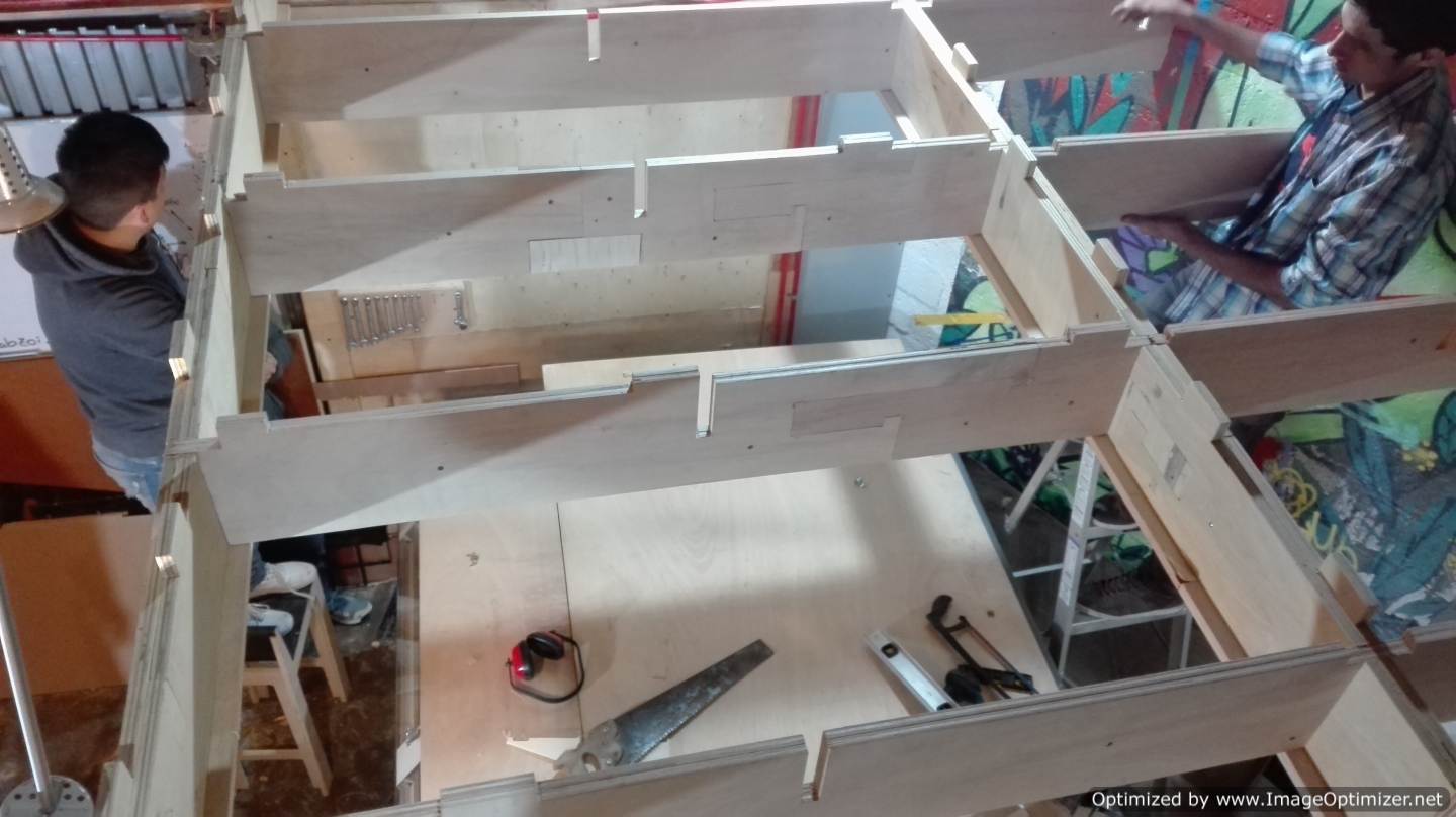
This is the FAB LAB that is self-constructed
From here we start the assignment; In our Fab-Lab we wanted to do something big and this is great. This is called the FABLAB that self-builds. As we said we are going to expand through a photos that show the space we had and the space we now have. As the work is quite large, we have an initiative, call architectural interns who want to learn this crazy world of digital manufacturing. And we had a good reception about 15 people. A very hard work to work with several people at once. But hey, what do we look for with this call? The FabLab seek cooperation and integration in community this is something great and very profitable.
.png)
.png)
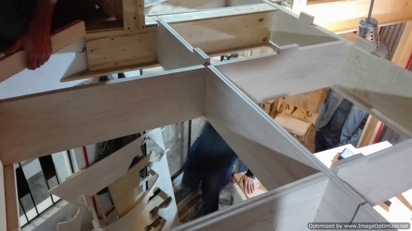
We have several processes throughout this extension that have divided our work to help make this equipment so big, we have beam equipment, secondary support equipment, bridge equipment and flooring equipment. Each team has as one of its members a student of the FABAcademy, in my case, I am in the bridges team.
What is this bungee team? Well, in designing a small bridge that will connect a staircase with a passage that is already created, which is the challenge here and then design it with digital units, manufacture it and finally test it with the people who design it.
- We started with the design process and we obtained the following result.
- Then I created a new Model according to the size of the CNC
- Import the file in dxf that was generated from Rhinoceros.
.png)
.png)
.png)
- We rotate the file, we must look for the Rotate tool in the sssistant tab
.png)
.png)
.png)
.png)
- I do not know if it is considered a technique, but I like to select the lines that are of milling and the holes for drilling. I still do not discover how to work with layers in ArtCam. I do not know if it is considered a technique, but I like to select the lines that are of milling and the holes for drilling. I still do not discover how to work with layers in ArtCam. To select use the shift key and the mouse I click on each line or group, after selecting all I right click and select All Group and this is a group. This is very suitable when I do milling or drilling.
.png)
.png)
.png)
.png)
- First, I configured the perforation in this work. in the toolpaths tab, I look for the drilling tool.
The parameters for the perforation are:
I need this hole to be 3mm, the milling tool is 6mm and the material is 18mm
.png)
.png)
.png)
.png)
.png)
.png)
.png)
.png)
- And finally I press Now
.png)
- Now we are going to perform the milling configuration. In the toolpath tab I look for the profilling tool I select it and it will change to another screen.
.png)
.png)
- I change the depth value from 18 to 18.2, my instructor suggested me to put it, in this way we make sure it reaches the end. Something very important and that I forgot to mention is the safe zone, this means the height that the milling sweats in Z from zero to move from one point to another
.png)
.png)
- We select the milling that we are going to use in this case a 6mm
.png)
.png)
- I configured the thickness of the material, a window with a slider appears, this slider I put it on top, this defines as zero point the top and the 18 mm that will travel downwards
.png)
.png)
- I selected the group and I put the name to this work and click on Now
.png)
.png)
- At the end I save the files in .tap mm format
.png)
.png)
Now with the files ready we go to work with the CNC
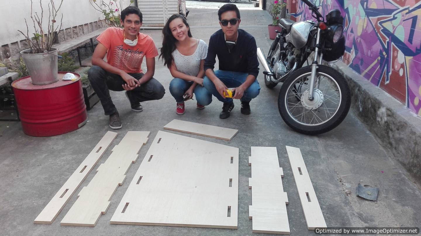
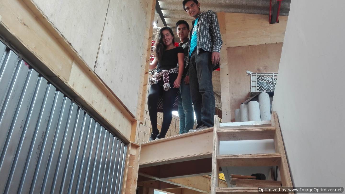
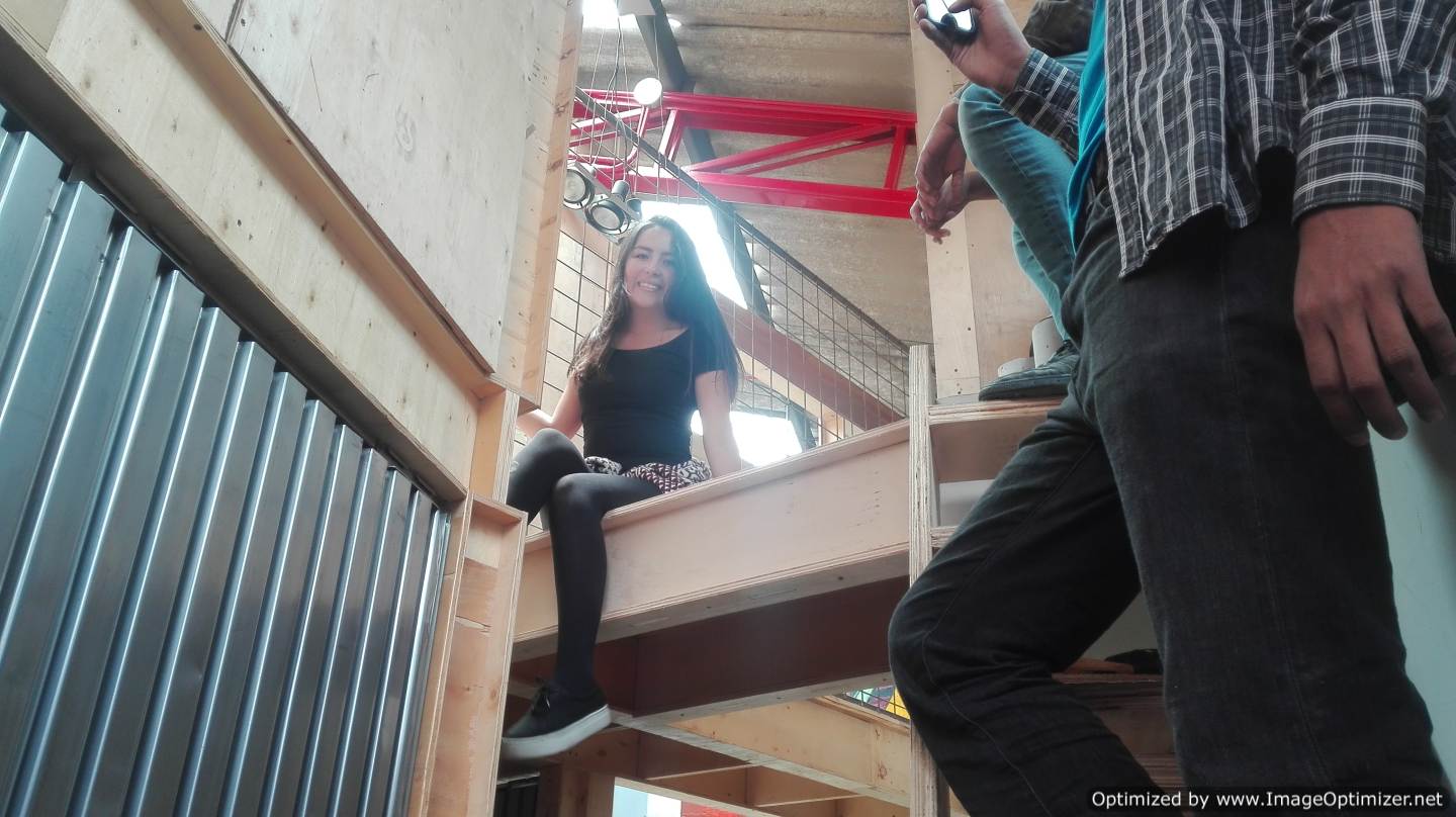
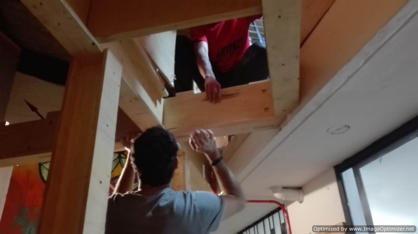
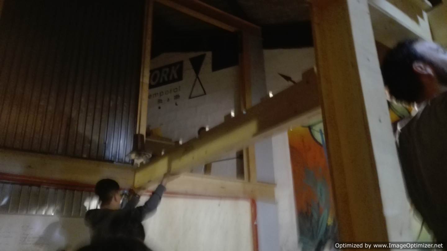
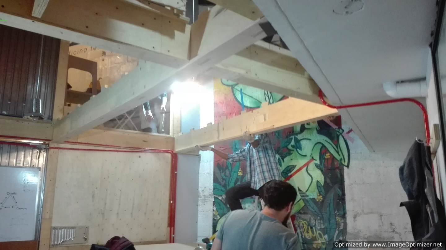
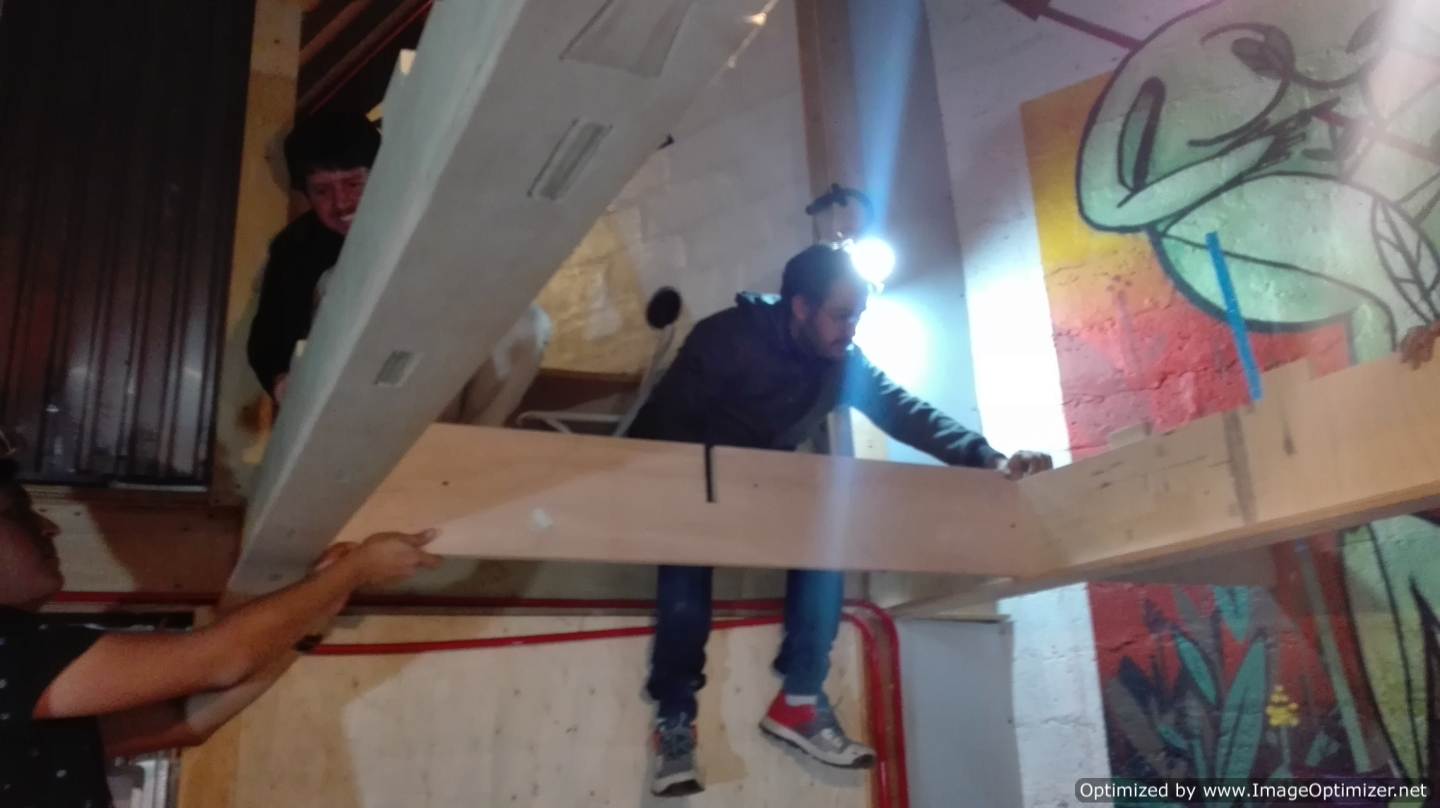
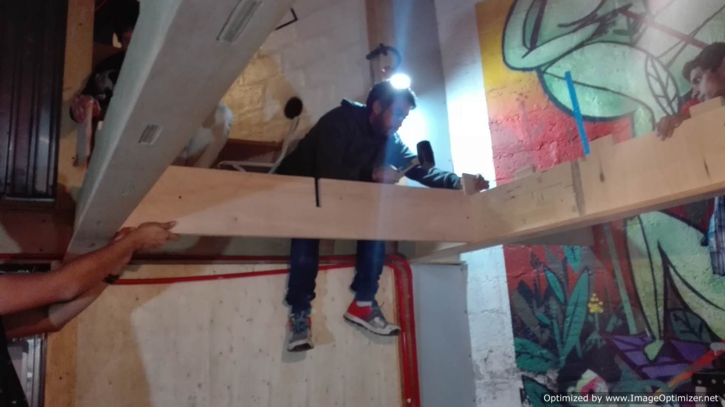
This is my group with which we worked to design the access bridge, with them after doing the parts in the CNC, we assembled the bridge we decided to put rubber for more security, this point was key because after assembling it we must go to the assembly.
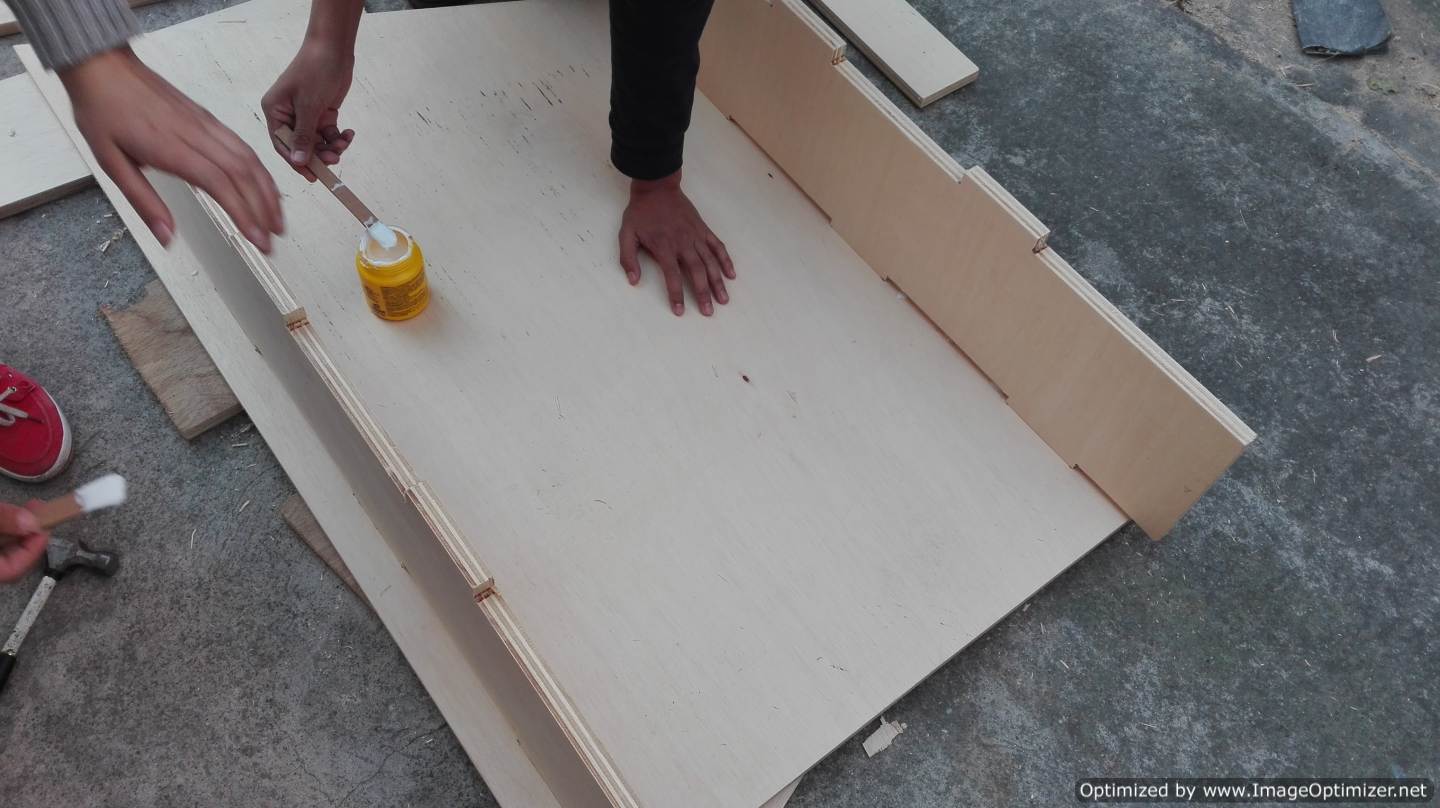
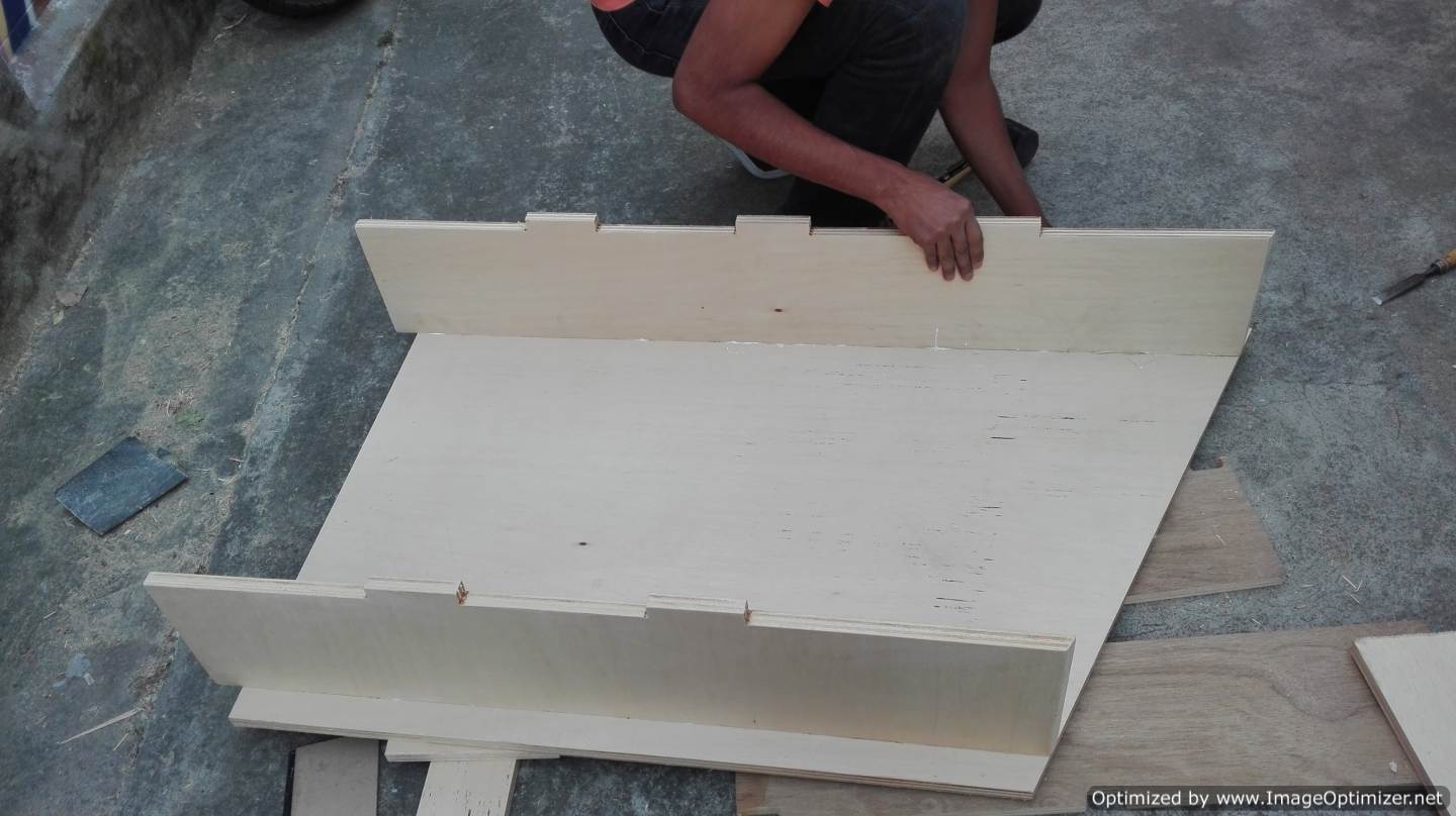
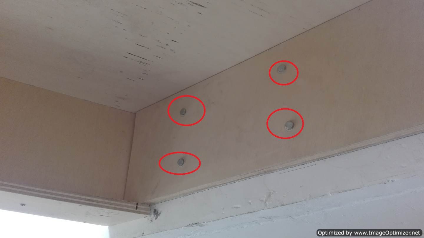
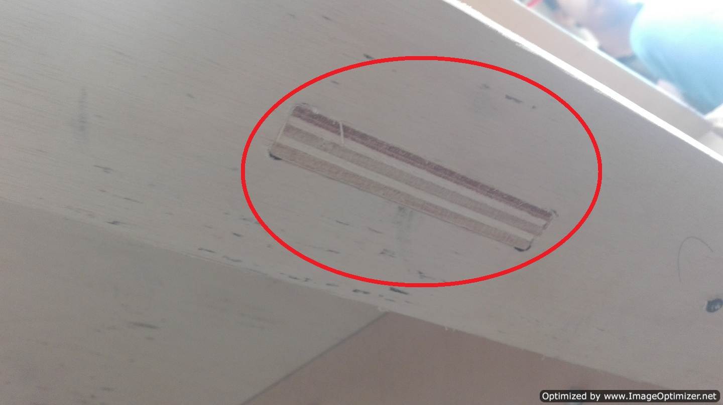
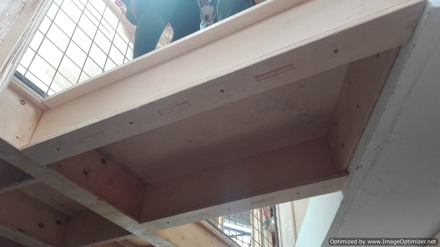
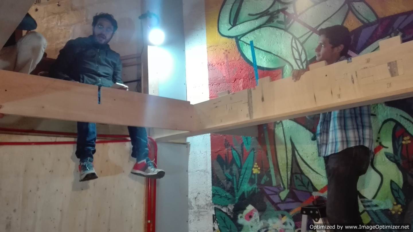
During the assembly we have to take into account two very important points one that must fit into the structure that already exists and the other must be anchored to the wall, these points we had very much in mind in the design. The anchor to the structure and wall was made with screws, you can see the digital joints very clear.
The moment of truth came the final test. The 2 boys and the girl with whom they worked covered the bridge with a great fear, but after remaining like 5 minutes on the bridge they are now calmer. How incredible our bridge worked.
Our work does not end here I present the extension process of our FabLab.
As I mentioned before we split into teams then I will present some support towards the other teams. The designs of floors, beams and secondary supports are completely ready.
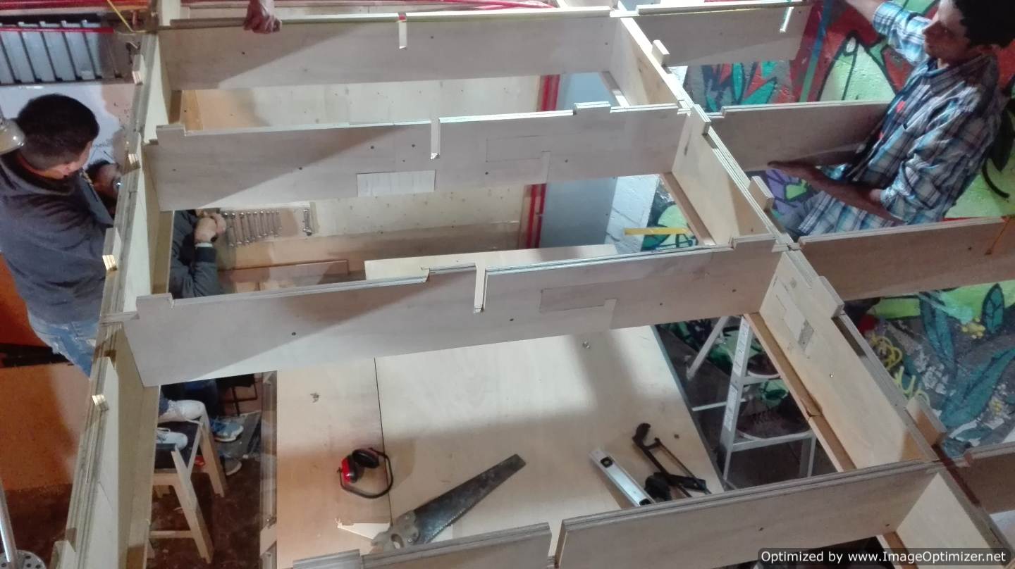
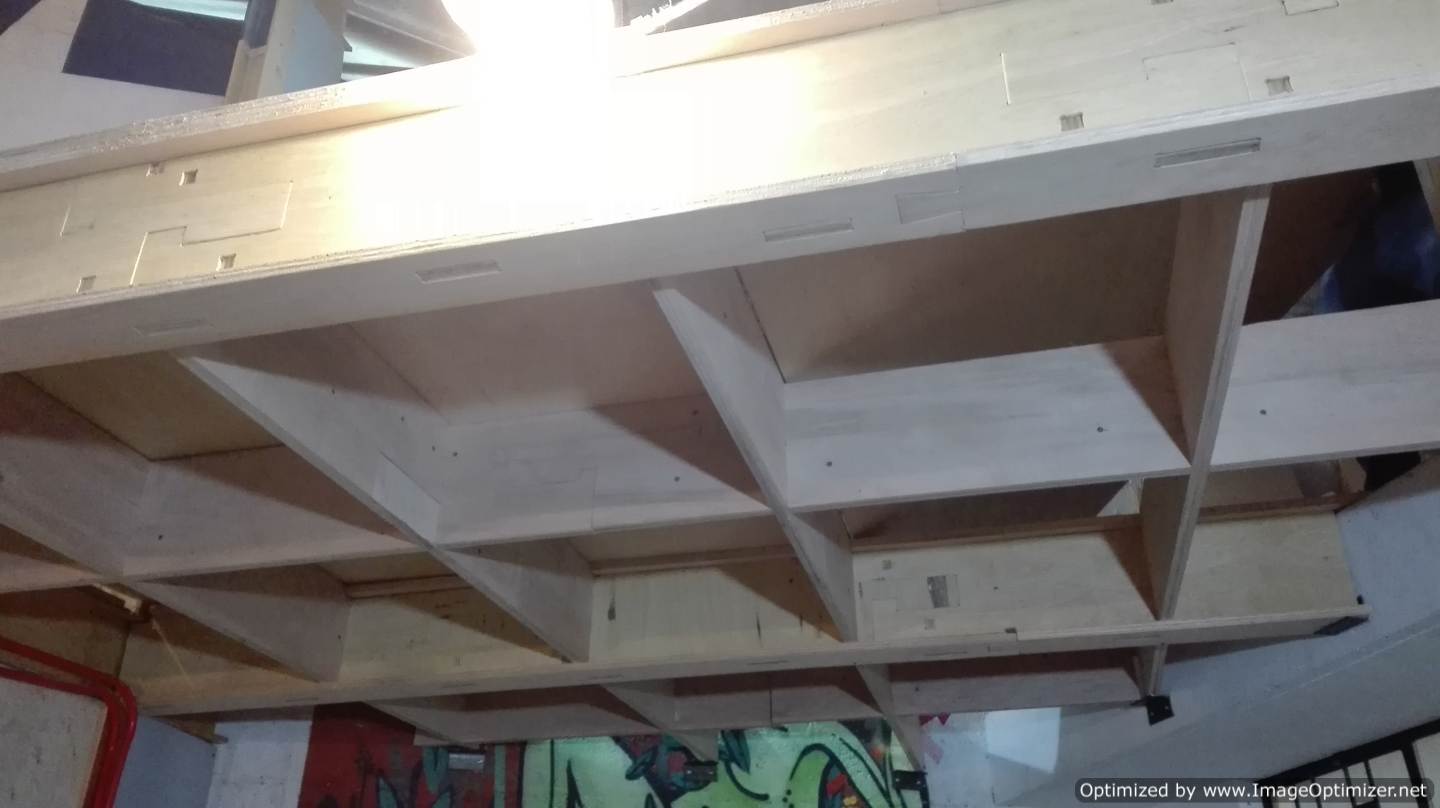
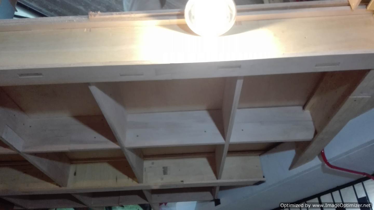
We have in mind that the beams are the ones that support all the weight, so we decided to do with material of 20 cm, but we also decided to reinforce more, then we put 2, one after another, remembering that the joints between the pieces should always fit with the pin of union for a fixation between beams. The secondary supports are made of 15 cm equal doubles with the same logic as the secondary supports in this case they no longer carry taring but only join by means of screws. For the beams we need to generate the shape of an I. As for the secondary supports they must be able to anchor to the beams. It was a great challenge for the beam and secondary supports team.
Design of beams
Design of secondary supports
Design of floors
.png)
.png)
.png)
.png)
During milling, it is necessary to take into account that all the lines are closed, because in truth it was a very big problem when trying to generate the files in artcam, luckily in Artcam there is the possibility of identifying these errors, this helps us to recognize the point to analyze in the design software.
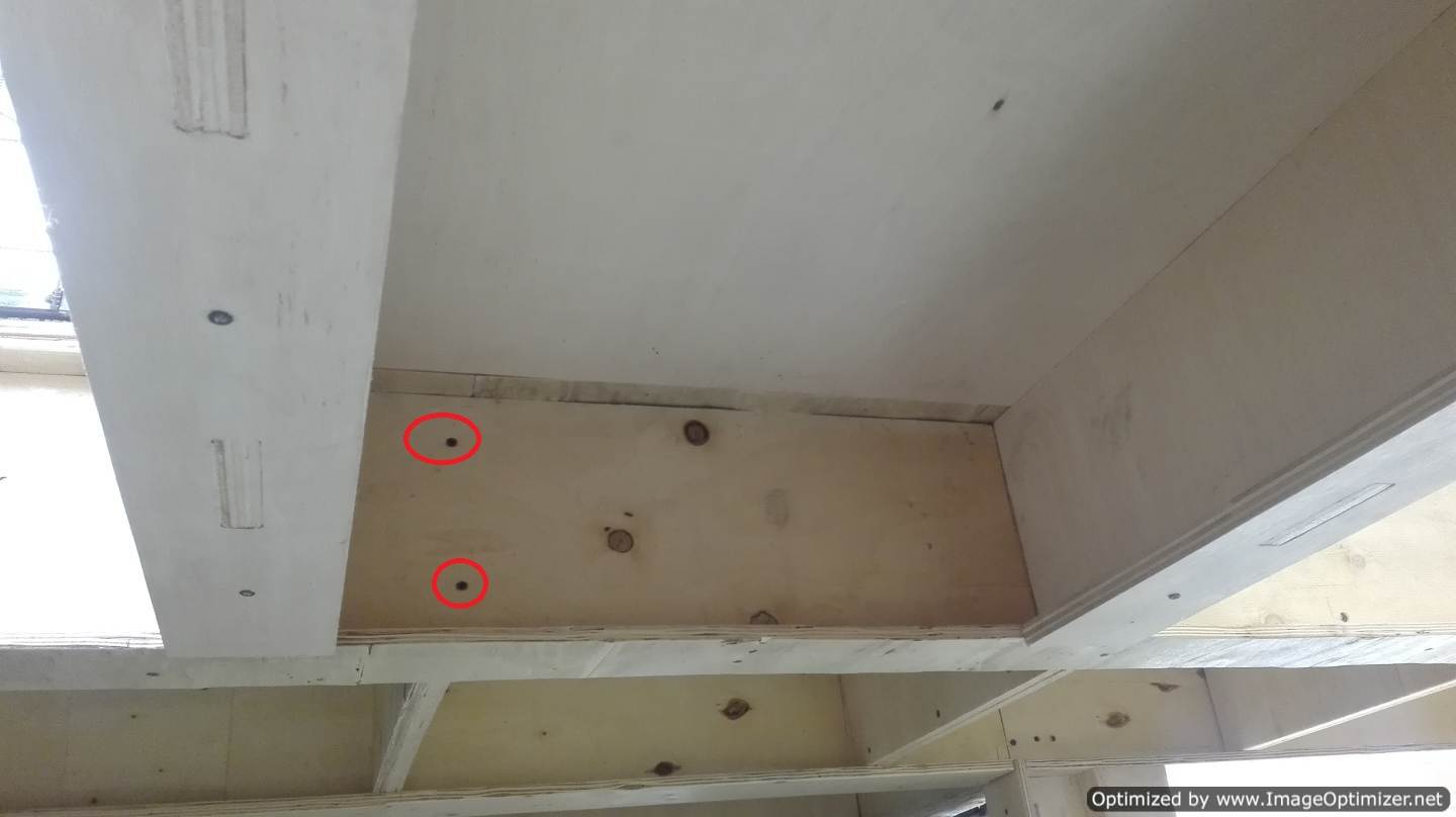
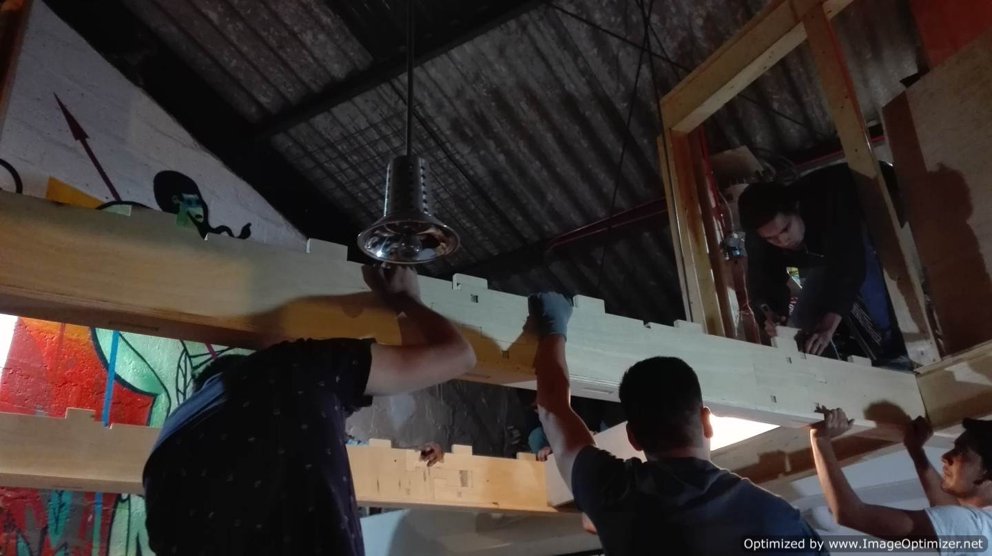
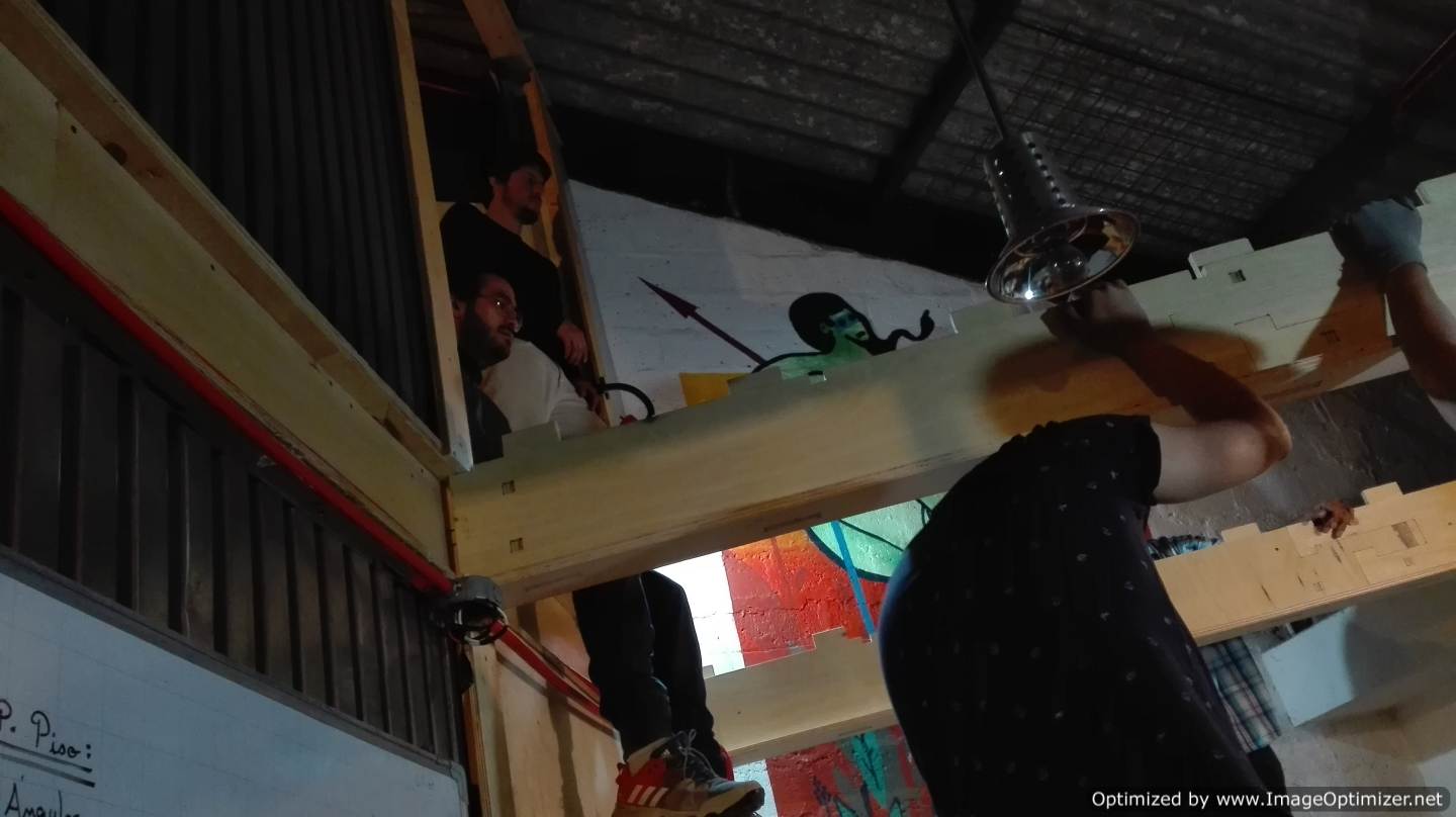
I do not want to remove much information from my colleagues so I will not focus much on this point, since their team was in constant work. Now as for the complete union was something very complex, because the architect with whom we worked decided to cut a beam, this made everything change, we tried to adapt to this change and we achieved in itself to rezlizar the union and a test on the structure . You can see how the digital joints allowed us a very ideal press fit for the structure to divide the weight evenly.
The final
CONCLUSION
-
I need to learn Rhinoceros with the parameterization plugin, it is easier to change a value and the whole design is reconstructed.
-
Group work is essential if the idea is created something big, each person has different skills that are used in this process.
-
The digital joints, together with the tolerances and the parametrization are very important points is the essential part before starting with a job.
-
The feeding speed, the filling rate and the configuration in the machine are important to perform an excellent job, it is necessary to select the correct depth cut because the mill cutter has its working limit.
-
Something I learned is that I have to place small bridges so that the pieces do not come loose and can be damaged. He mentioned that this is called profiling options.
-
One very important thing that Fabio Lopez taught me was to perform nesting, this helps to relocate the pieces of an object in a small or large space for better use.