ELECTRONICS DESIGN
Group assignment
Use the test equipment in your lab to observe the operation of a microcontroller circuit board
 For this week we first identified the equipment that the laboratory owns, for the moment we have a multimeter that helps us identify and recognize the values of voltage, resistance and current that in theory is the most important. We did a test in a simulator called proteus, here we were able to perform a basic circuit and how to simulate it.
This program is very good has several instruments that help us understand the instruments and their operation, such as:
The communication port simulates an ftdi.
An osciloscope simulates a digital oscilloscope.
Here we also have voltmeter and amperimeter.
For this task we use a commercial arduino and a breadboard to perform the equipment tests, as we saw in the simulator we now place a multimeter to analyze the circuit and compare the result.
.png)
How to add arduino to proteus
NECESSARY FILES
There are two files that we will need:
Both are included in a compressed file in Rar, at the end of the documentation.
- ARDUINO.LIB
- ARDUINO.IDX
INSTALLATION
This step will depend on the version of Isis Proteus that you have and having the aforementioned files already decompressed:
For version 7.X:
You will have to copy the files that are included in the RAR, at the following address:
- 32-bit Windows: C: \ Program Files \ Labcenter Electronics \ Proteus 7 Professional \ LIBRARY
- 64-bit Windows: C: \ Program Files (x86) \ Labcenter Electronics \ Proteus 7 Professional \ LIBRARY
Code for the Test
void setup() {
  // initialize digital pin LED_BUILTIN as an output.
  pinMode(LED_BUILTIN, OUTPUT);
}

// the loop function runs over and over again forever
void loop() {
  digitalWrite(LED_BUILTIN, HIGH);   // turn the LED on (HIGH is the voltage level)
  delay(1000);                       // wait for a second
  digitalWrite(LED_BUILTIN, LOW);    // turn the LED off by making the voltage LOW
  delay(1000);                       // wait for a second
}
How add the code of Arduino in proteus
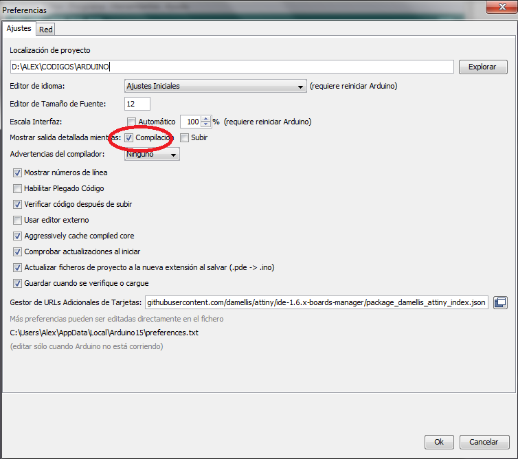
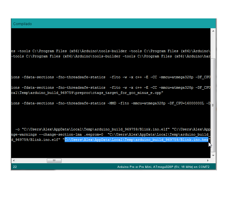
In arduino select preferences and "show detailed output while" click in compile. After compiling in the lower screen a text is shown, we go to the end and look for the address of the .hex code
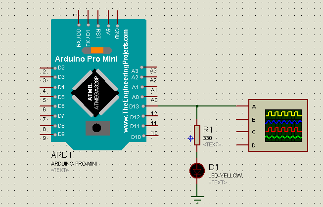
First we make the circuit and place an oscilloscope in the output of pin 13 of the arduino
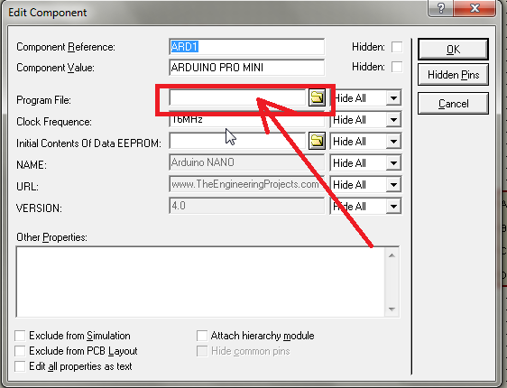
second we place the .hex code that we copy after compiling in the direction shown, this screen is taken out by double clicking on the component. We just paste the address and press ok.
Finally we press play and we will see the result shown by the oscilloscope
.png)
With the help of the multimeter we perform the test on the board of my partner Quiliro Ordoñez, we verify the value of the output voltage of the pins
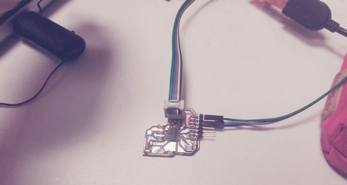
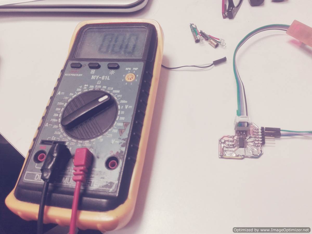
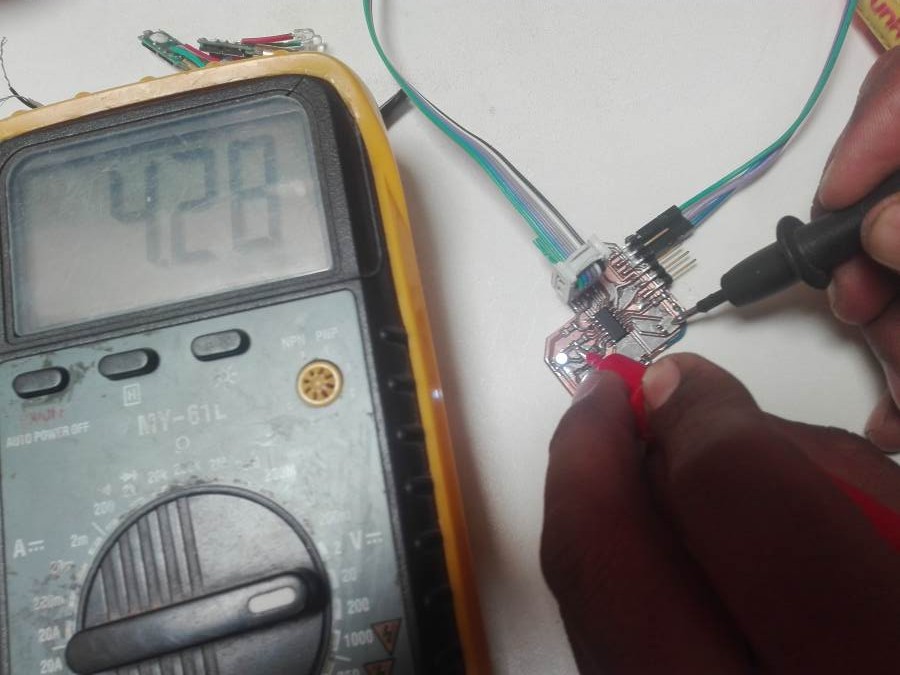
To use the multimeter we place the knob in the position that allows reading voltage, with one of the tips "COM" we place it in gnd and the other end in the output we want to measure, there are times when the scale of the multimeter is very small and you have to live with it, this was not the case.
Individual assignment
* Redraw the echo hello-world board,add (at least) a button and LED (with current-limiting resistor),check the design rules, make it, and test it
* Extra credit: simulate its operation and render it
I have experience to create circuit boards, I use programs like ISIS, ARES, Liveware and PCB wizard.
You can download their free version from the following link Proteus Design Suite Livewire + PCB Wizard.
I have a minimum experience in Eagle, this time I will take advantage of the academy to learn this powerful software.
I decided to use version 6.3 of Eagle because I already had it installed on my computer, I did not want to install the new version, I believe that version 6.3 can work very well if I need something extra then I will install the new version.
If you do not have an Eagle first you have to install it here I leave the link EAGLE
First we need to download and install the Fab component library. the library can be downloaded in the following link FABLIB , right click and select save link as, save to a known path and finally copy inside the lib folder located in the eagle software installation folder. I recommend you do these steps without opening the software. After copying open the software in the control panel go to the libraries click on the tab and search fab.lbr right click and select use.
 |
.png) |
.png) |
.png) |
From this moment the library is ready to be used
Process to design a new circuit
Start EAGLE Open the project folder, select the folder with the name eagle press the right button and first create a new project. It creates a folder of red color remember to enter the name and in the end we close EAGLE. From the fabAcademy tutorial, download the basic schematic hello.fdti.44 schematic
.png) |
.png) |
Go to the documents folder, inside the EAGLE folder there is a folder with the name of the project that we created. Paste the downloaded schematic into this folder.
.png) |
.png) |
Start EAGLE and you can see that a new schematic file already exists. We opened the schematic and began to add the different components
It is very important to know that there are basic rules for designing schematics and pcb board in the pdf show the rules. This PDF is property of the electronic technology department of the University of Seville. Visit the link
Show very clearly and precisely the design with its components, power, input and output pins, connection with other components. Provide if it is not all at least clear information so that it can be reproduce and / or modify the design properly, such as names and values of components. Create a schematic where you can make a complete and exhaustive list of materials, a well done schematic is the starting point for a PCB. It is good to align the components for a correct reading, with their values and names in order to identify them faster. A very good technique is to order by trying to get the signal to flow from left to right, inputs to the left and outputs to the right. Another way is to order the components as we would like the PCB to be. Avoid unnecessary crossings if there are places the union points or failing to create connection lines by means of labels. If possible, it is good to group the components according to the same logical group.
| ADD COMPONENT | SEARCH COMPONENT |
|---|---|
.png) |
.png) |
| LED AND BUTTON | MOVE THE COMPONENTS |
|---|---|
.png) |
.png) |
In my design I wanted to create a name for the lines below, I will show you how it is done, it is a very interesting and very simple process after practicing.
.png) |
.png) |
.png) |
I also create the name and label of the component. Each line has its name. When you want to make a connection between a line and a device, first ask us to confirm the connection. Finally we have to change the resistance value for the led. Now we have to calculate the value of the resistance.
.png) |
.png) |
.png) |
.png) |
I found a link where you can easily make this calculation. Now we have to calculate the value of the resistance according to the led
.png) |
.png) |
.png) |
.png) |
The components are placed in a disorderly manner this is normal when starting, our job is to order in the most ideal way.
.png) |
.png) |
This is my second design. in this design I add a led rgb, I try to make the board very small. I think my design is very interesting incorporates all the elements in a relatively small board.
.png) |
.png) |
.png) |
.png) |
The final board is as follows.Now we have to generate the png file with the strokes and another with the edge.
| FINAL | SELECT DISPLAY | TRACES DISPLAY |
|---|---|---|
.png) |
.png) |
.png) |
CREATED THE PNG ARCHIVE OF THE TRACES AND CUT
From this point we remember the last classes, week 5 is the most suitable for this work.For this work it is very necessary to use the gimp software. Next I leave you the strokes and the cut.
| ORIGINAL | TRACES | OUTLINE |
|---|---|---|
.png) |
.png) |
.png) |
 |
 |
Fabrication
I made a board and unfortunately the bed is uneven, and the board has many errors.
| CONFIG CERO POINT | SOFTWARE CNC LINUX | BOARD WITH ERROR |
|---|---|---|
 |
 |
 |
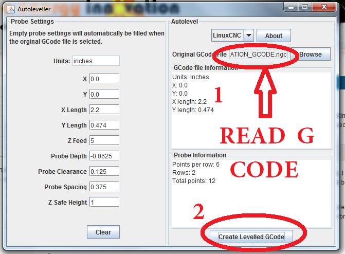
There is a way to eliminate the error due to unevenness, in Linux the autoleveller software exists. This software allows you to self-level according to the points you take within the work area. The autoleveller software generates test points in the work area. The machine takes each point until the sensor on the axis and detects its contact, after taking the points it goes to perform the milling with the new leveling. When generating the file it is saved in .tap format that is easy to read by the linux cnc software.
It is very clear the milling between the two boards, it is noted that it is very effective after applying the software
 |
 |
 |
|
 |
The next step is to weld the components in their location, the most complicated elements of welding were the RGB LED and the resonator.
 |
 |
 |
Programming the device
I use the program that Neil proposed us and make some modifications so that the led rgb works. You can find the original code in this link hello.ftdi.44.echo.c
Then I leave the new code to use the led rgb and the button. I modified the code that Neil gave us.
Take into account that only the main is modified, the rest is the same
int main(void) {
   //
   // main
   //
   static char chr;
   static char buffer[max_buffer] = {0};
   static int index;
   static int i;
   //
   // set clock divider to /1
   //
   CLKPR = (1 << CLKPCE);
   CLKPR = (0 << CLKPS3) | (0 << CLKPS2) | (0 << CLKPS1) | (0 << CLKPS0);
   //
   // initialize output pins
   //

	DDRA|=(1<<4);      // PA4 configuration as output
	DDRA|=(1<<3);      // PA3 configuration as output
	DDRA|=(1<<2);      // PA2 configuration as output

	PORTA|=(0<<4);    // The led starts off
	PORTA|=(0<<3);    // The led starts off
	PORTA|=(0<<2);    // The led starts off

	DDRB|=(0<<2);	  // PB2 configuration as INPUT
	PORTB|=(1<<2);	  // Config the internal pull-up

   set(serial_port, serial_pin_out);
   output(serial_direction, serial_pin_out);

   static int i;
   while((PINB&(1<<2)))
	{
		switch(i)
		{
			case 7:
			PORTA&=((0<<2)|(0<<3)|(0<<4));
			break;

			case 6:
			PORTA&=((0<<2)|(0<<3));
			PORTA|=(1<<4);
			break;

			case 5:
			PORTA&=((0<<2)|(0<<4));
			PORTA|=(1<<3);
			break;

			case 4:
			PORTA&=((0<<2));
			PORTA|=((1<<3)|(1<<4));
			break;

			case 3:
			PORTA&=((0<<3)|(0<<4));
			PORTA|=((1<<2));
			break;

			case 2:
			PORTA&=((0<<3));
			PORTA|=((1<<2)|(1<<4));
			break;

			case 1:
			PORTA&=((0<<4));
			PORTA|=((1<<2)|(1<<3));
			break;

			case 0:
			PORTA|=((1<<2)|(1<<3)|(1<<4));
			break;
		}
		i++;
		if(i>7)
		{
			i=0;
		}
		_delay_ms(250);
	}
   //
   // main loop
   //
   index = 0;
   while (1) {
      get_char(&serial_pins, serial_pin_in, &chr);
      put_string(&serial_port, serial_pin_out, "hello.ftdi.44.echo.c: you typed \"");
      buffer[index++] = chr;
      if (index == (max_buffer-1))
         index = 0;
      put_string(&serial_port, serial_pin_out, buffer);
      put_char(&serial_port, serial_pin_out, '\"');
      put_char(&serial_port, serial_pin_out, 10); // new line
      }
   }
I follow the next tutorial to upload the code to the microcontroller

In my case the answers were the following
.png)
.png)
The Test
To finish we perform the respective tests.
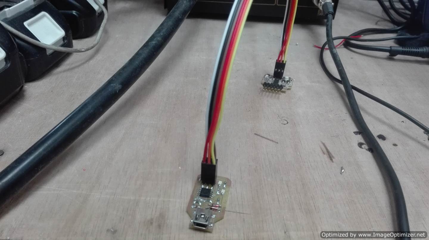
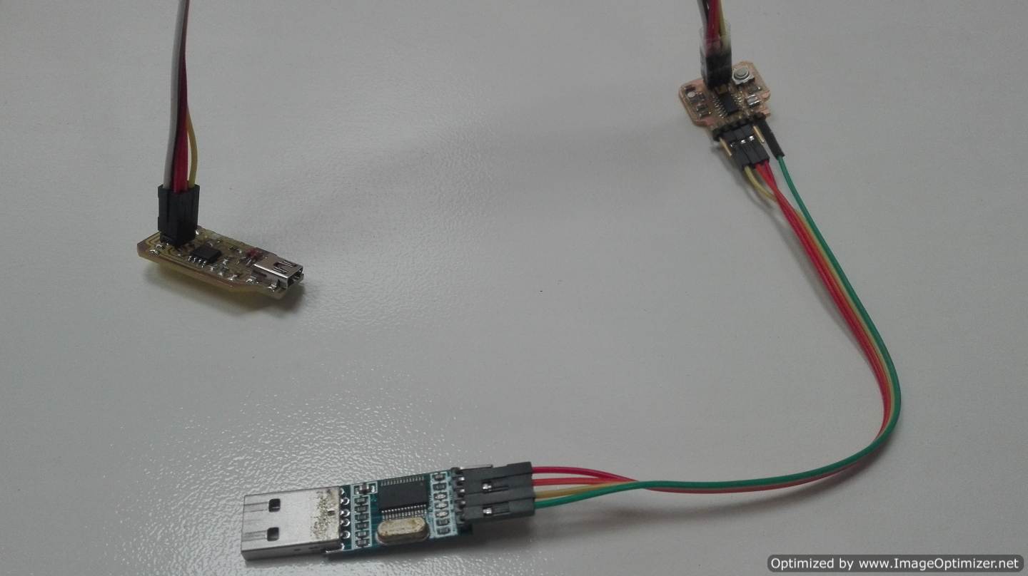
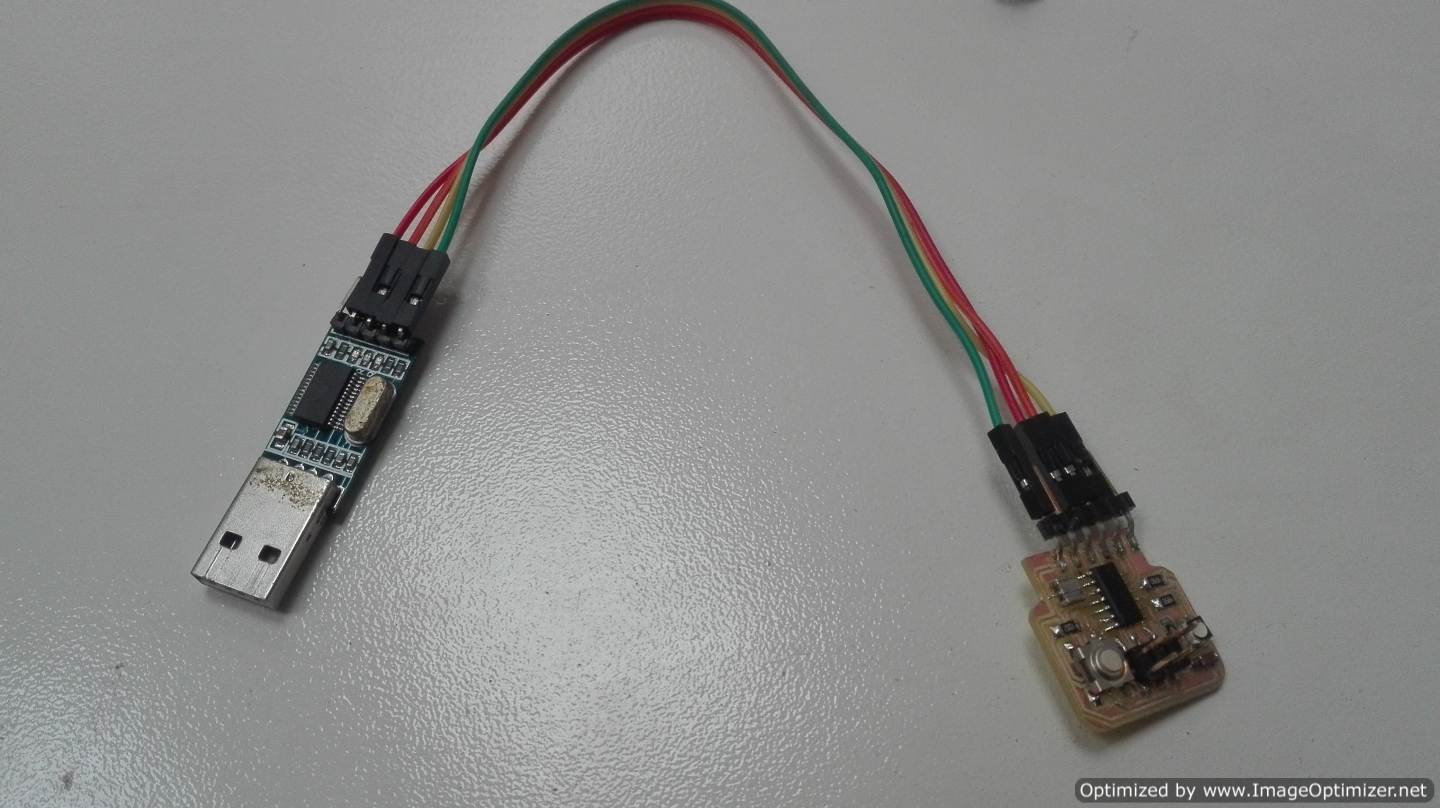
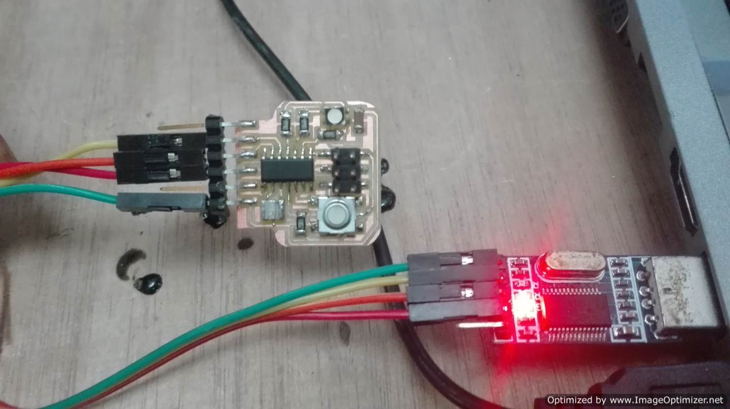
I in my case for communication use a module usb-ttl and the arduino ide to perform the communication test.
Remember that the connection form is attiny rx pin with tx pin usb ttl, and the same way attiny tx pin with rx usb ttl
Serial test with Proteus
In this test i use a simulation to verify, the code, the connection and the correct operation.
The software that i used is proteus, in this software include the virtual serial library with the code .hex in the microcontroller the next step is configure the virtual serial for the communication.
.png)
.png)
Finally after the test with simulation i understand how is the form of doing the real test. I think that is necessary implement the simulation of electronic circuits, for embedded programming it is a great help.
Serial test with Arduino IDE
.png)
In this step i use a the Arduino ide to verify, the correct operation. Arduino has a monitor-serial to communicate with the ftdi our usb-ttl, the most necessary is select the port of the list and select the velocity of communication. In this real test send a letter and the microcontroller responds with the same letter and expects us to send another new letter, if you send the second letter is attached to the previous one in this way it forms a message.
The simulation
 |
CONCLUSION
- You can use many different programs to design electrical circuits
- I can miniaturize my designs.
- The electronics has taken much of our world, we find it in most places.
- It is not necessary to be an expert to create a PCB board just a bit of constancy.
- There is a very big world in circuits that I still do not understand and that I discovered in the fabacademy