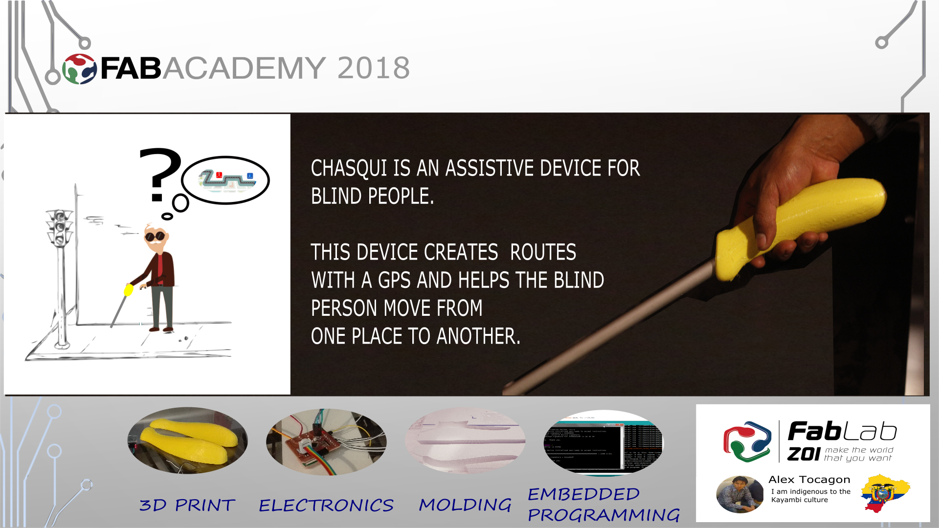
THE FINAL PROJECT "CHASQUI"
In this video we see as recognized brands are looking for inclusion to the blind and create specific devices
The problem
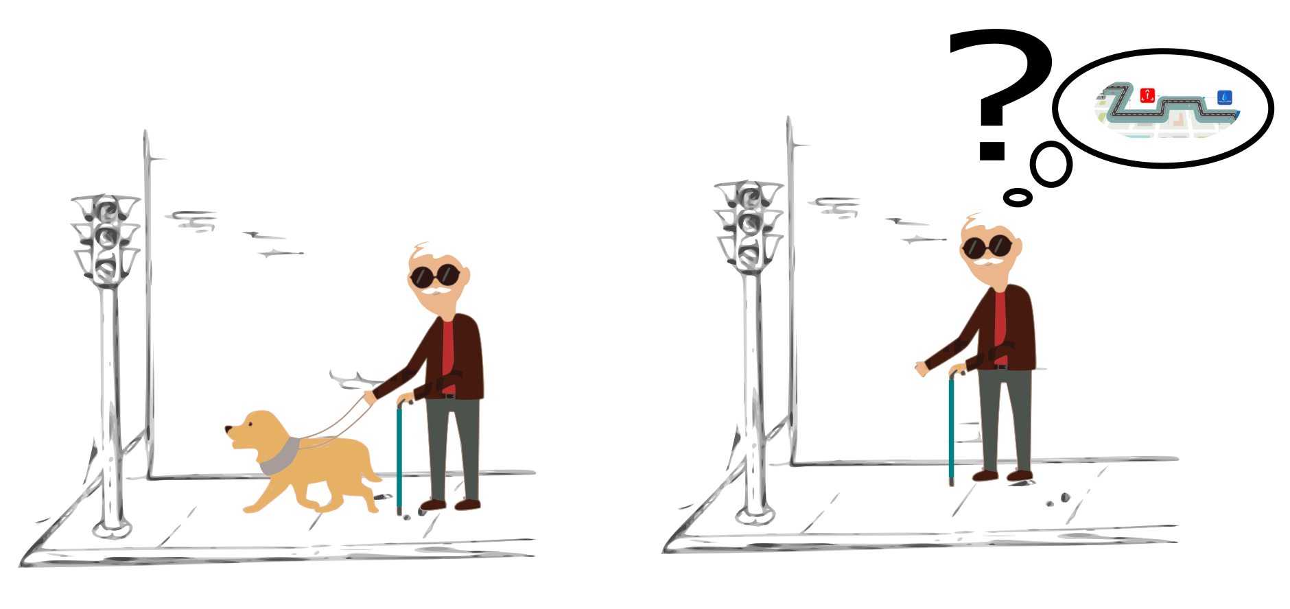
The problem begins with the blind man's fear of navigating the city in a new place.
The Solution
Create a device is useful to mitigate fear and generate security for the blind when going down the street
 The idea is to create a device that allows blind people to walk down the street without the help of a guide, this will help them mitigate the fear of leaving and helping in their personal safety.
Since I did not know the needs, I had an interview with a blind boy from my city.
The idea was to make a handle but he mentioned that he had an accident where his watch was lost.
They do not like to use cell phones because they fear being robbed and finally I tell myself that the cane is the most important thing and its main means as a guide.
I started looking for information about smart canes to get an idea of what my final project would be like.
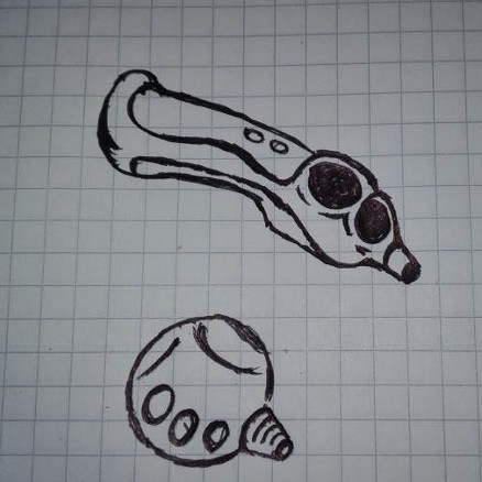
The idea is not to create a cane but to create a device that fits the cane.
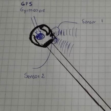
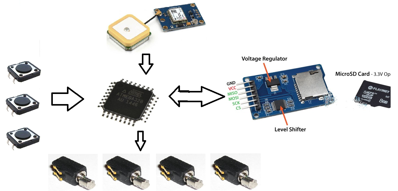
 Here is an explanation of the system.
The stick tedra a gps that will let you know the current position of the blind and a reference map of the most common and basic places, will also have an mp3 player and 4 vibrating motors located in the front, back, left and right.
How do I want my device to work?
When I walk down the street and reach a corner this device will warn me by means of a voice player from the nearest places within a range of 20 m.
Depending on the location, the motors will vibrate in the following way:
front and then give the reference "example church", back and then give the reference "example bus terminal",
left means "this" and then it will give the reference "example park AMERICA", right means "west" and then give the reference "example" FABLAB ZOI ".
My current location is the bus terminal, when the blind press a button or reach a corner automatically the device looks for places near this point according to the value of the gps.
This data is reproduced by an audio device, for me
The device will allow the blind person to go from one point to another without the help of a guide.
The device should be very comfortable and adequate, it should be small and the most important thing should work without internet. It is my main objective.
I know it's a long way to go, but I want that with my knowledge and help from the Fab Academy, the project is a reference for future studies.
This is my chronogram to my final project
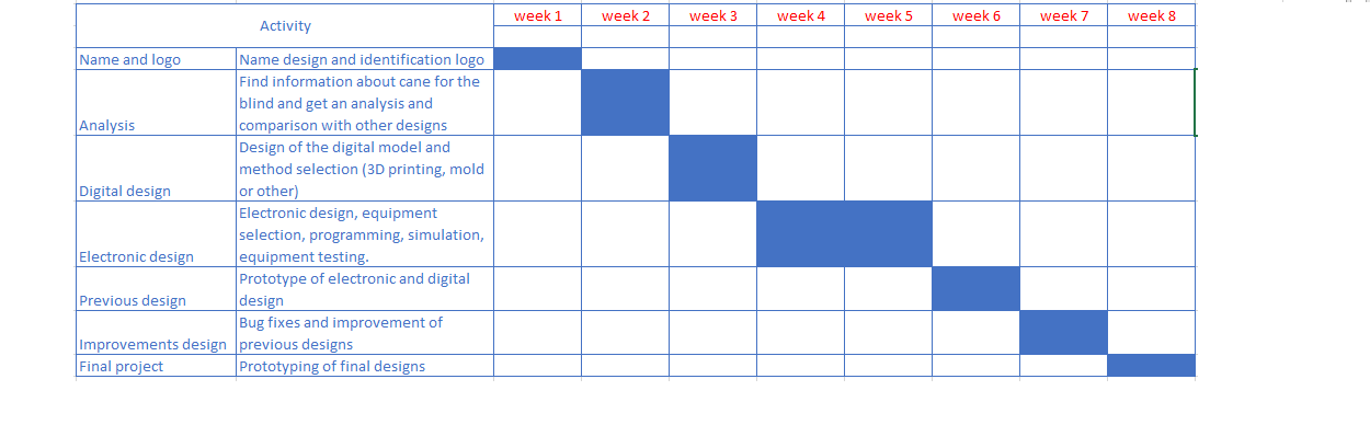
Name and logo
Why first select the name and logo?
It's the way I'm going to identify my device and how I'm going to make it known to the public
Chasqui:
The chasqui was a young runner who carried a message or message in the postal system of Tahuantinsuyo, moving from one post to the next immediately.
He was the personal messenger of the Inca, who used a system of posts to deliver messages or objects.
Under this same concept my device seeks to be that messenger for the novident, looking for reference points or posts that are the places that identifies the device and give orientation.
Analysis
Blind Stick Navigator
Team MeRo: Mohammad Hazmi
Published July 29, 2016 © LGPL
A blind assist tool that provide obstacles notification and GPS location to the guardian / authority via SMS.

THE INFRARED WALKING CANE
BY: TROY TURNER
Published 06/29/2015

Simply called the Safe Stick, this revolutionary walking stick for sight-impaired individuals goes beyond the limitations of traditional designs, utilizing a network of checkpoints at landmarks like bus stops and intersections to help users navigate safely and more effectively. The design relies on RIAS (Remote Infrared Auditory Signage) technology installed at the landmarks that communicate with the walking stick and signal an auditory message to the user with details on their location as they approach a checkpoint. For nighttime use, a bright red LED flasher gives additional safety by notifying drivers of the user’s location.
Previously presents 2 types of canes; but with the same objective, after reviewing the two designs, my objective does not deviate the system must be within the cane and is not something external.
When reviewing the 2 design I can see that the first 2 use positioning or GPS devices, the 2 use devices to detect distance, the 2 allow to communicate with the cell phone although the first design is very large can be minimized, the second design is better and has several sensors that I could take into account for my project.
At this point I realized that it is a bad idea to design the object or model before having the board ready so I decided to continue with this step and then continue with the design process.
Now I will describe the process of design and construction of each of the elements of the device for blind, in the process will be taken into account the choice of the material that best suit the proposal to allow them to have a good performance
Electronic Design
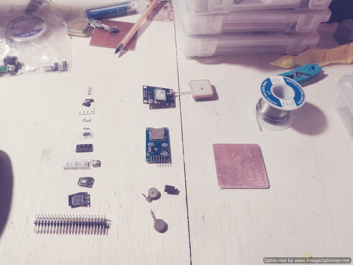
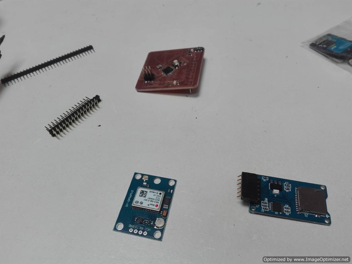
Selection of components
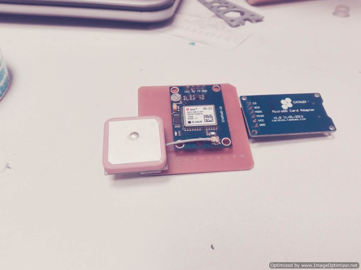
Ublox NEO-6M GPS
For week 11 , I decided to explore a GPS.
Description 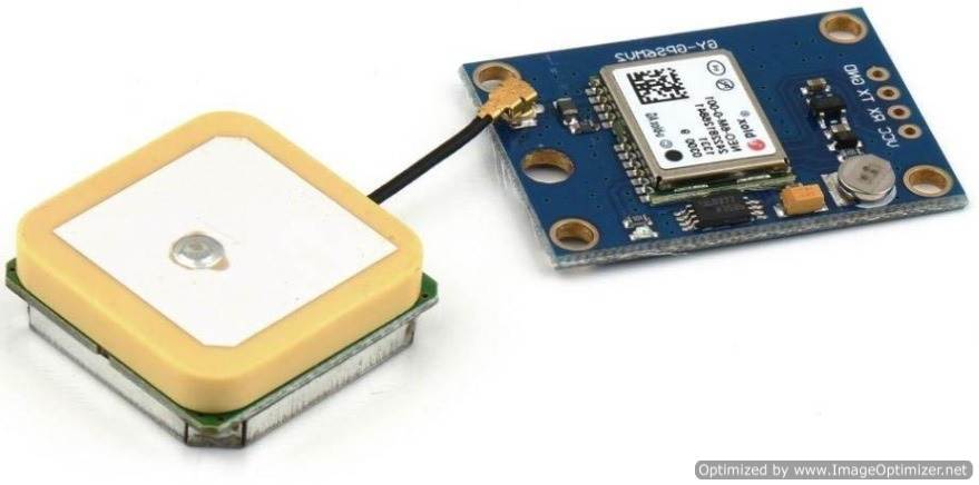
    * Ublox NEO-6M GPS Module Aircraft Flight Controller
      Arduino MWC IMU APM2 projects robots NEW
    * Ublox / u-blox NEO-6M GPS module with antenna and build-in EEPROM
    * This module is compatible with APM2 and APM2.5,
      and EEPROM can save all your configuration data.
    * Interface: RS232 TTL
    * Power: 3-5v
    * Baudrate default:9600bps
    * Power supply :3V-5V
    * Models: GY – GPS6MV2
    * The LED signal lights
    * The default baud rate: 9600
    * Module size 25 mm x35 mm/0.98"x1.37"(inch) (approx)
    * The antenna size: 25x 25 mm/0.98"x0.98"
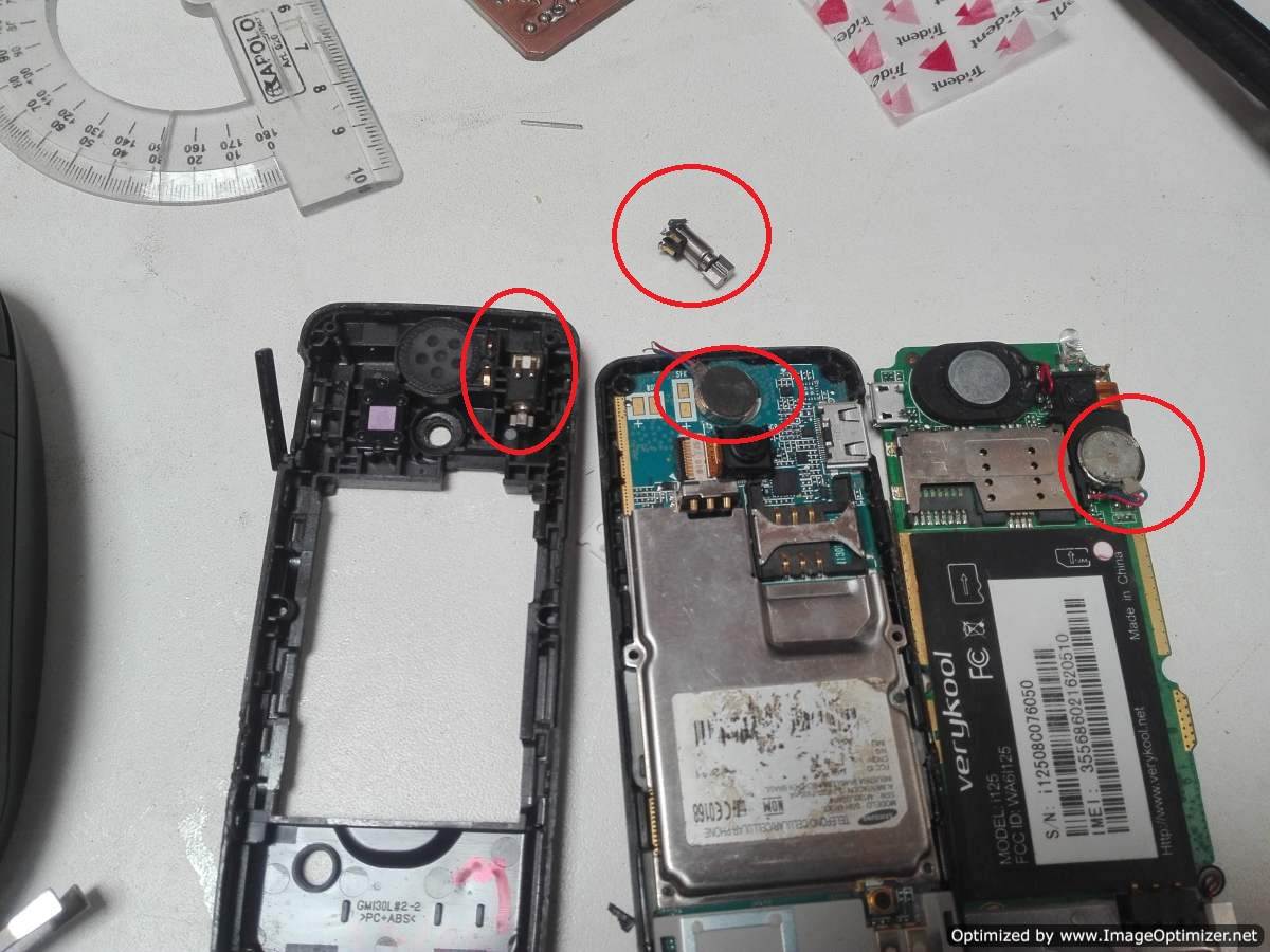
I need a very small DC motor and the price on the market is almost 3 dollars. But I prefer to recycle damaged cell phones.
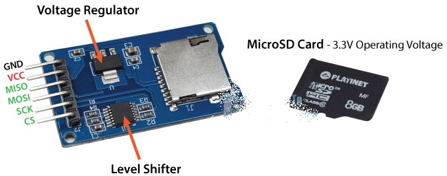
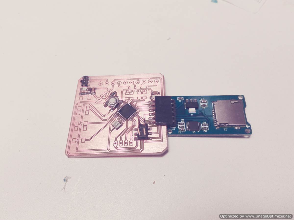
I also need a module to read the SD card
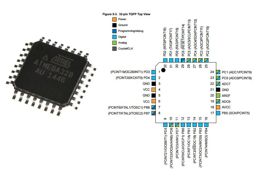
The main component of this device is the microcontroller. In my case, I used ATMEGA328P for the following reasons.
1.- The device needs a SERIAL PORT to communicate the GPS, in my assignment of Input devices. I used the ATTINY44 but I had problemsi the reception data.
2.- I need the SPI port to communicate with the SD card
3.- I need 4 pins for DC motor,the motors test I also did it in week 12 of Output devices.
I describe the specifications of the microcontroller in the datasheet that I show below.
Electronic Production
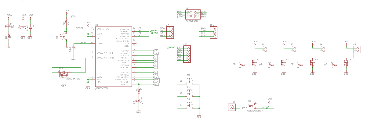
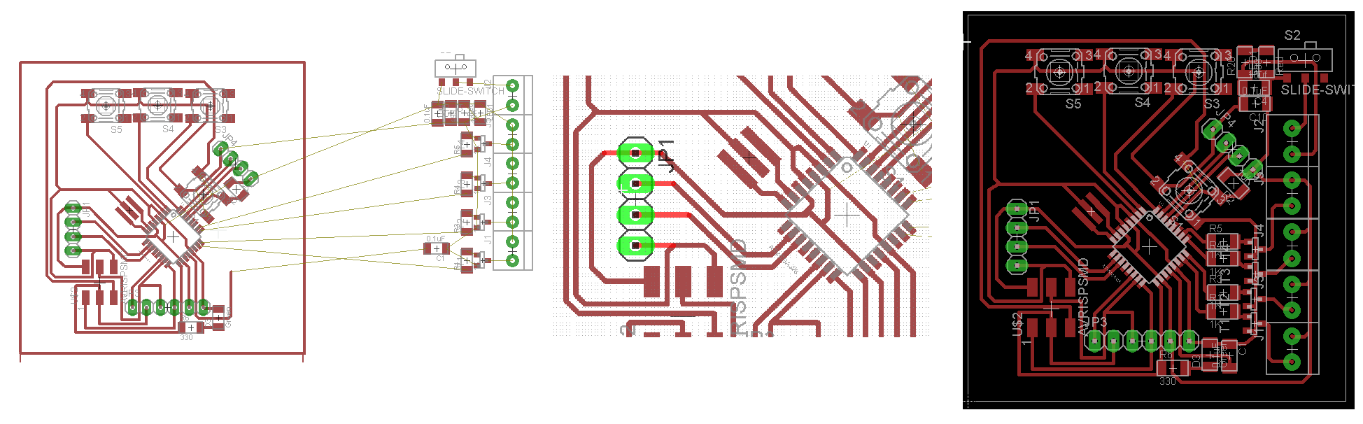
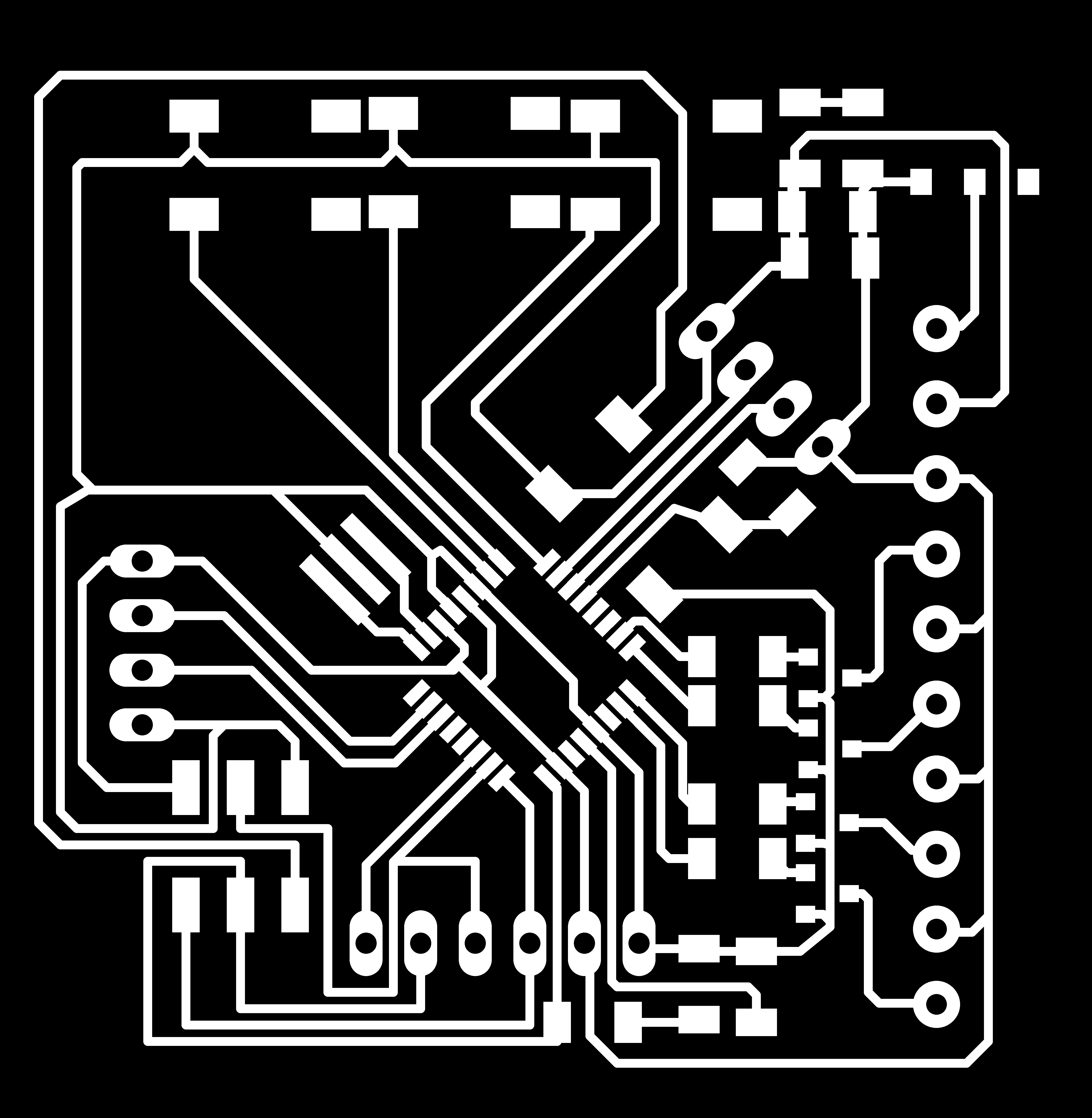
With the selected components, I will proceed with the schematic design and the board, taking into account that the board is small and that it contains all the equipment.
For the design of the electronic circuit board use the eagle software.
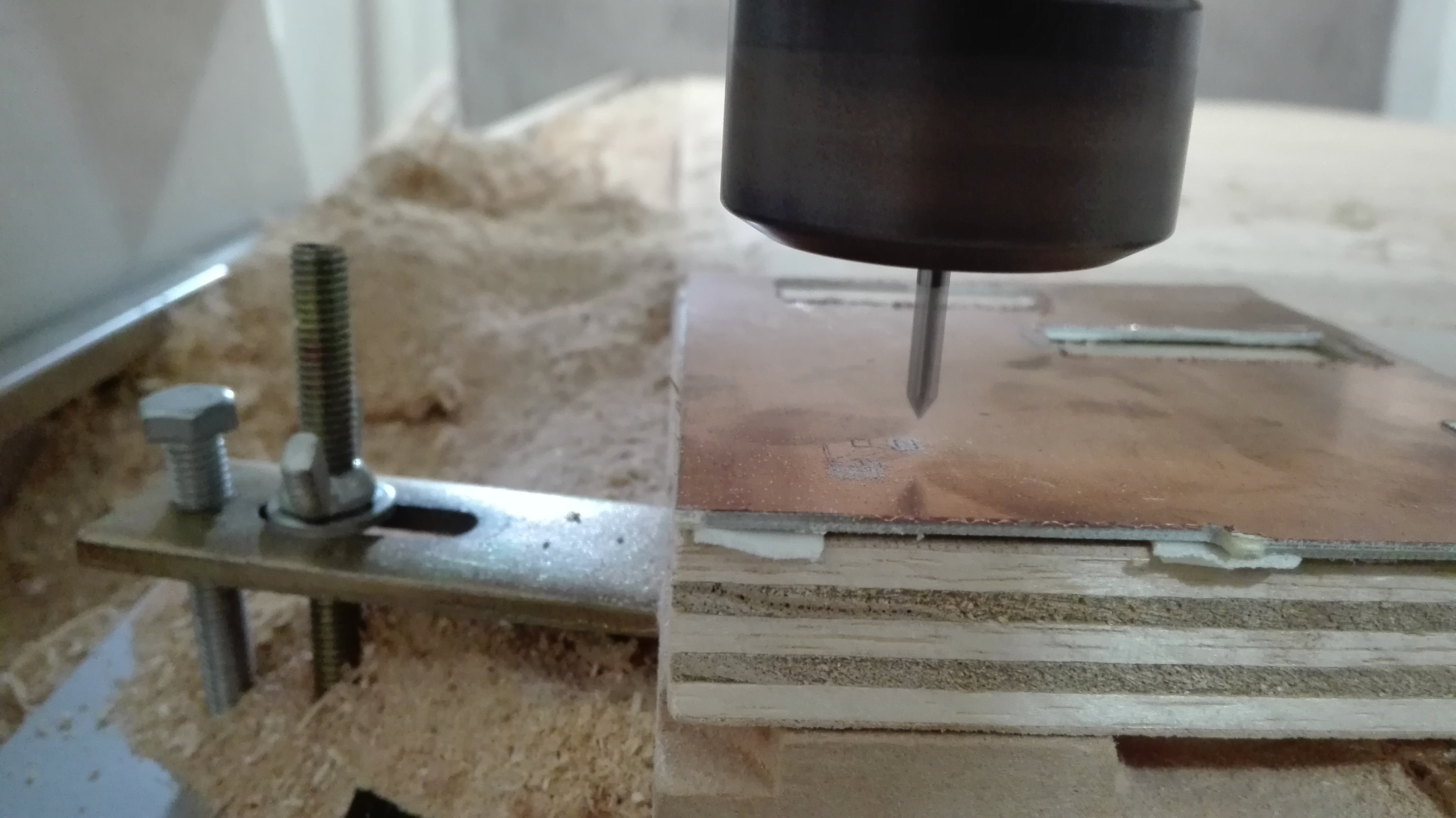
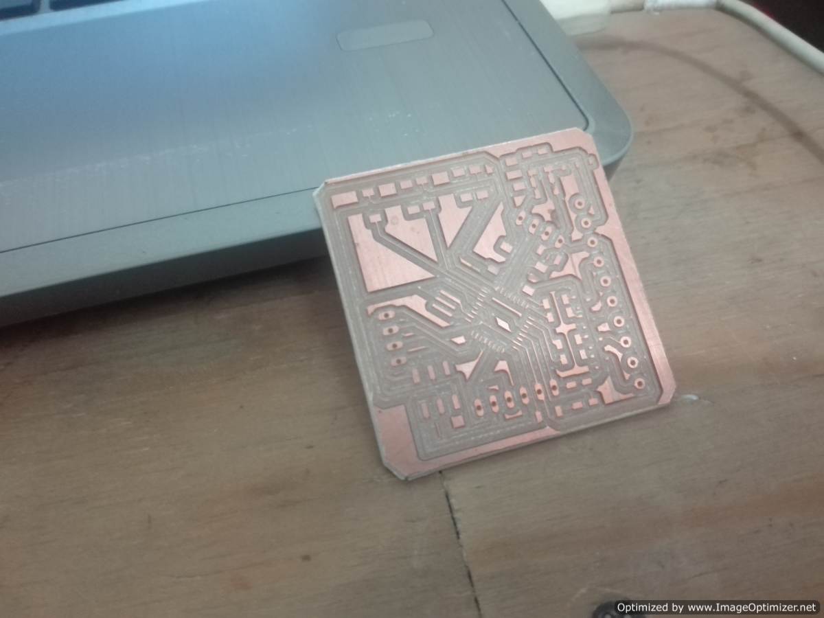
Electronic Production
For the manufacture of the pcb board use the CNC milling machine "CNC router 1325", the process can be seen in the assignment of week 8
Now I'm going to create the files for the traces and borders, now I create a contour in eagle that is exported along with the image.

When making the configuration the fabmodules I had a problem but solve it by changing the value of the diameter of the milling cutter.
The problem occurs because the G code does not pass through parts of the board, this fortunately was solved in a quick way.
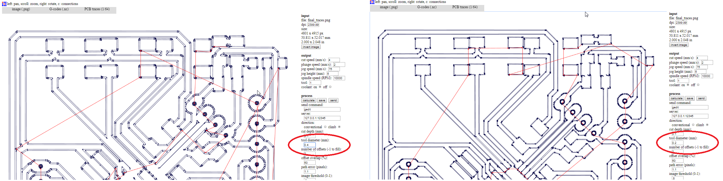
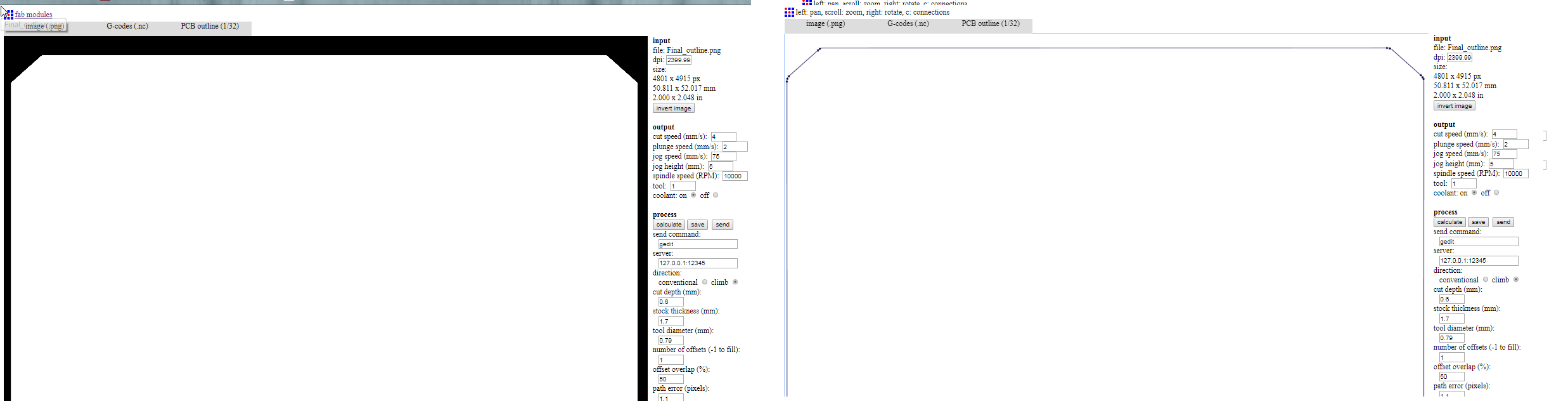
The configuration to make the G code of the outline is the most common we use a 1/32 cutter
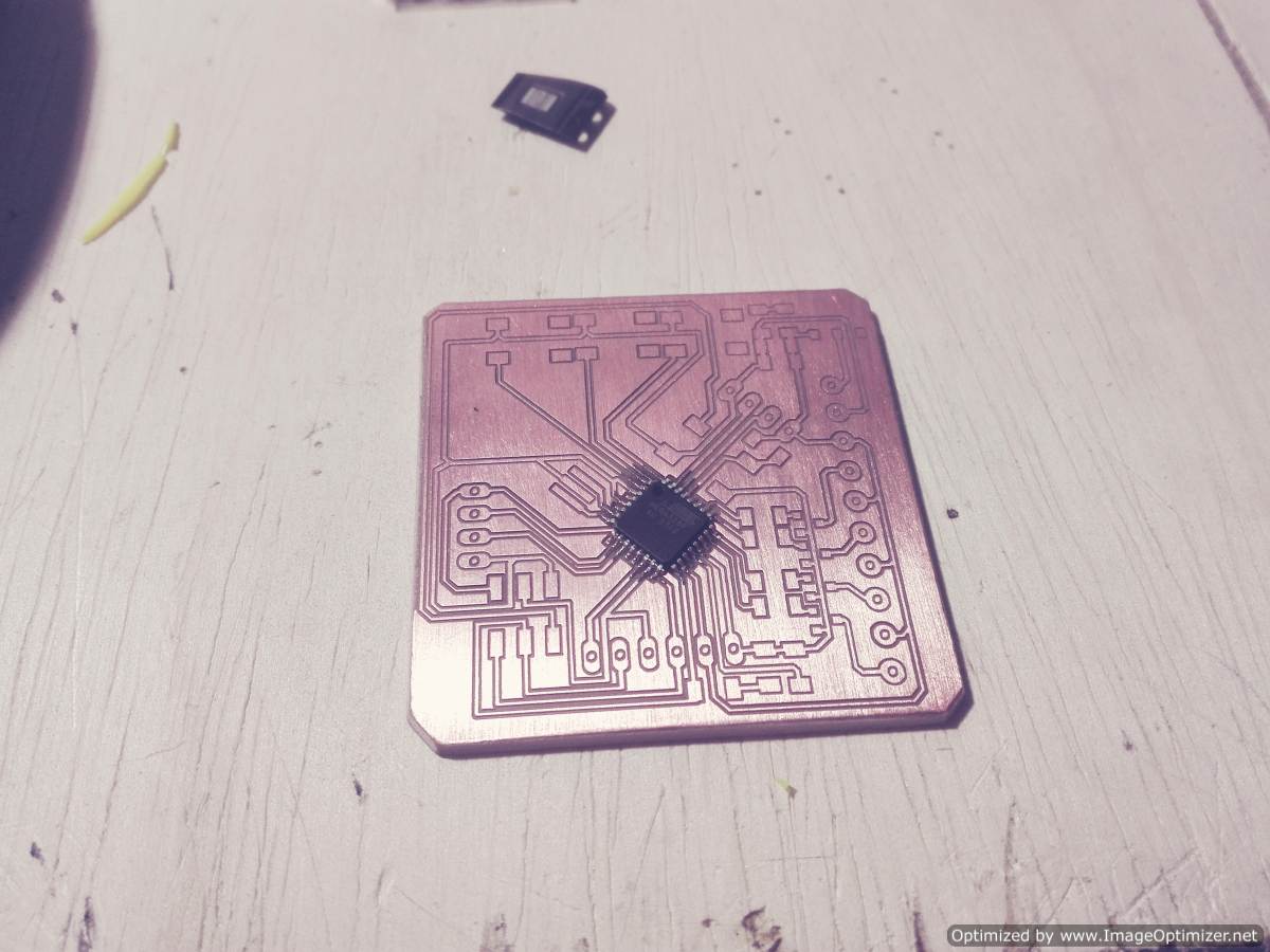
Fabrication
Welding of electronic components
Bill of Materials
Part Value              Device               Package      Amount
C   0.1uF              CAP-UNPOLARIZEDFAB   C1206FAB     2
C   10uf               CAP-US1206FAB        C1206FAB     1
C   0.1uF              CAP-UNPOLARIZEDFAB   C1206FAB     1
D   Green              LEDFAB1206           LED1206FAB   1
J   TERM-1X02-ADAFRUIT TERM-1X02-ADAFRUIT   3.5MMTERM    5
JP1                     PINHD-1X4            1X04         2
JP3                     PINHD-1X6            1X06         1
LED  Red                LEDFAB1206           LED1206FAB   1
R    1K                 RES-US1206FAB        R1206FAB     4
R    10K                RES-US1206FAB        R1206FAB     1
R    499                RES-US1206FAB        R1206FAB     2
S                       6MM_SWITCH6MM_SWITCH 6MM_SWITCH   4
S    SLIDE-SWITCH       SLIDE-SWITCH         AYZ0102AGRLC 1
T                       PMOSFETSOT23         SOT-23       4
U   RESONATOR          RESONATOR            EFOBM        1
U   AVRISPSMD          AVRISPSMD            2X03SMD      1
U    ATMEGA328          ATMEGA328            TQFP32-08    1
U    DC MOTOR           5V DC MOTOR                       4
U    GPS                Ublox NEO-6M                      1
U    SD READER          MODULE SD READER                  1
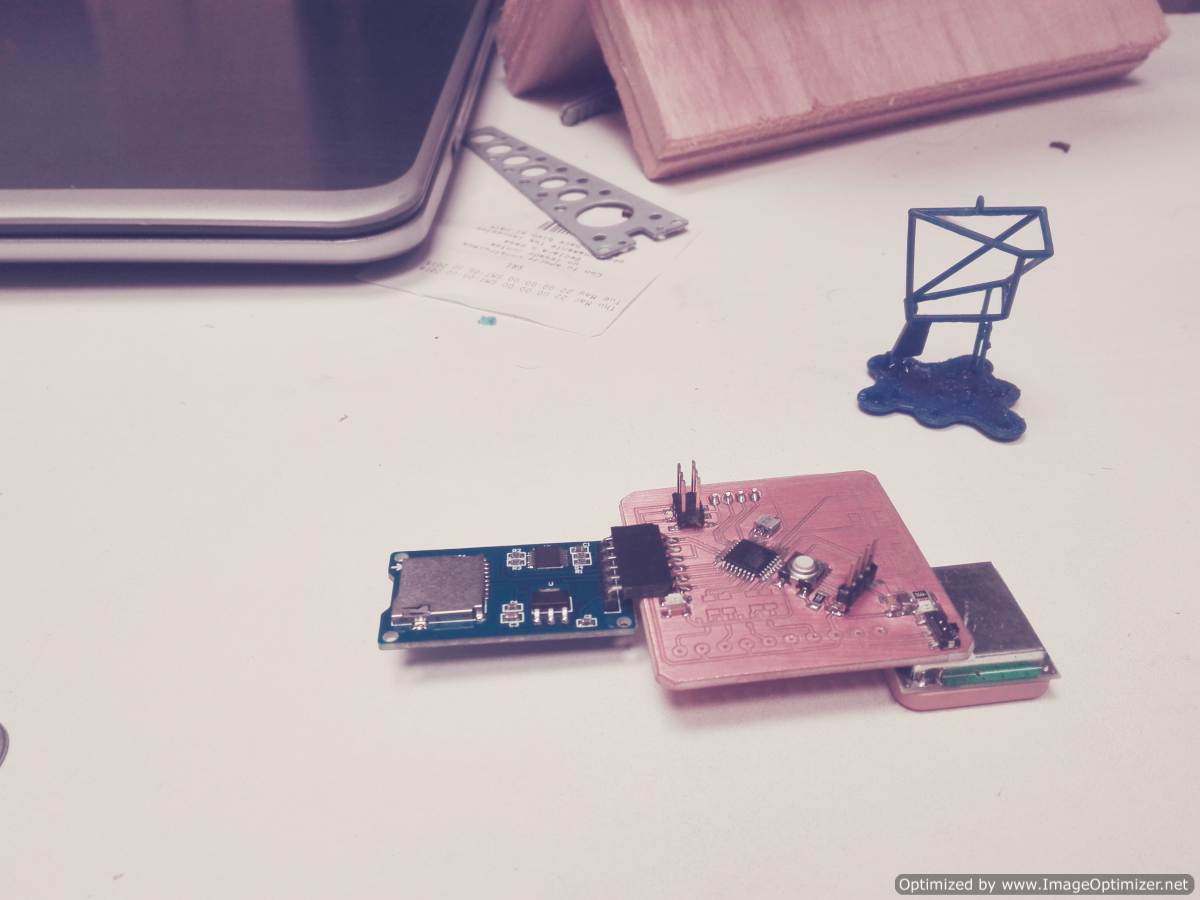
The assembly
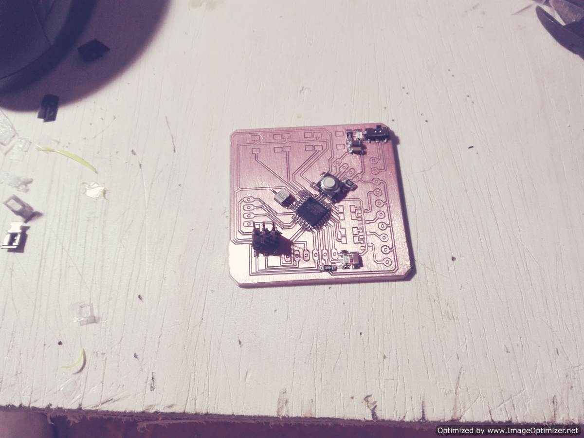
EMBEDDED PROGRAMMING
In this point, use the skills for programming, I use the arduino ide to communicate and up the code for the board
The program consists of 3 buttons that indicate the working mode:
Button 1 .- data storage second to second on the SD card for the creation of new routes.
Button 2 .- Track saved routes
Button 3 .- Will be a panic button. This is something new to implement, I know that for the moment I can not achieve it but my project will continue to grow.
What is the logic to identify if it is at the correct point or not
When generating a route, I need only points where the corners are, the others discarded them. I take these points as part of an equation.
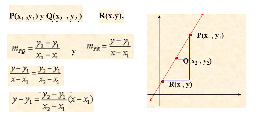
The point R is the beginning of the street the point P is the end point of the street and the point Q becomes the GPS data, I draw an equation with the point R and P if the GPS data satisfies the equation of the straight the user is in the right direction.
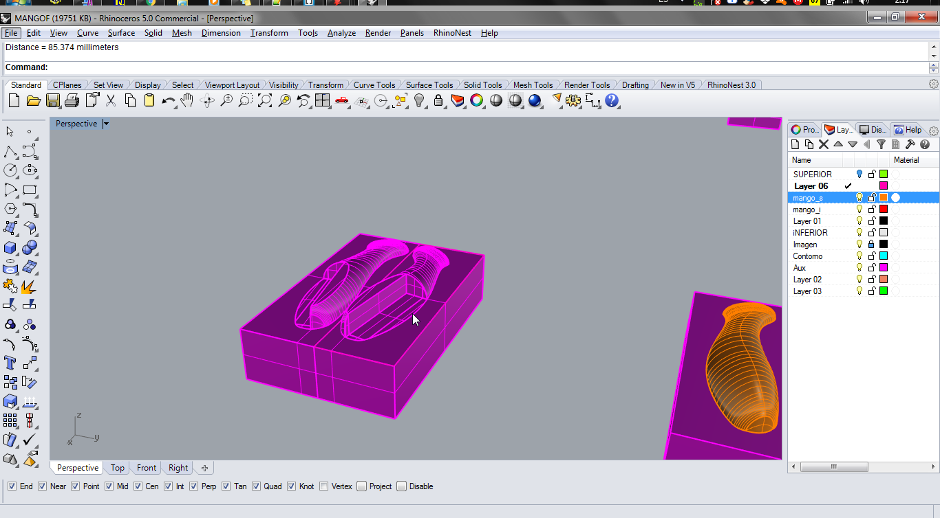
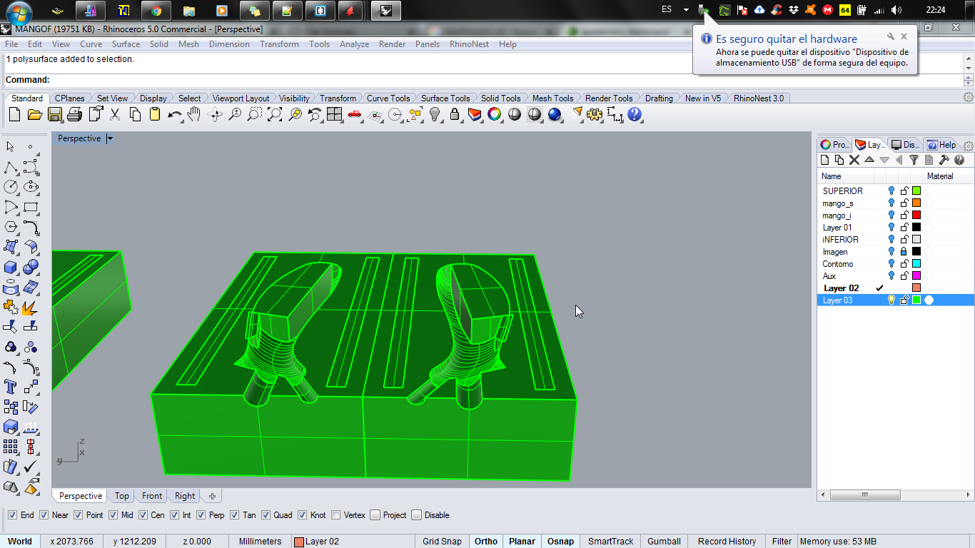
Digital Design
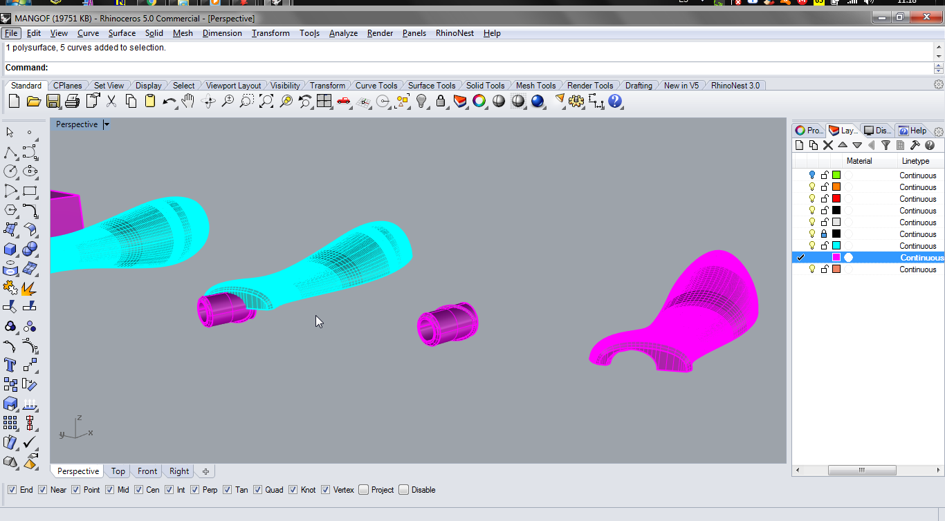
After finishing the process of electronic design and manufacturing programming, I went on to design the support handle for the metal tube and the cover for the handle.
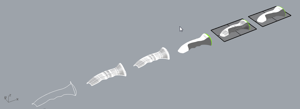
In week 3 the I make a simple design for my final project, I take the design and change, the second design is great in the week 10 complete the design.
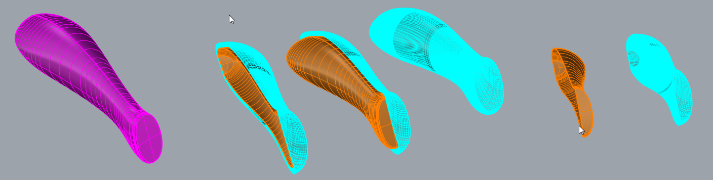
Then change your view and create a thickness on the handle. For the handle to be symmetrical use the mirror command. With several curved lines try to give volume to my figure, but an effective and faster way was to use sweep 2 rails
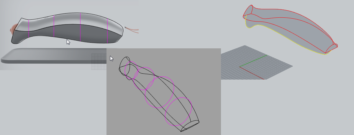
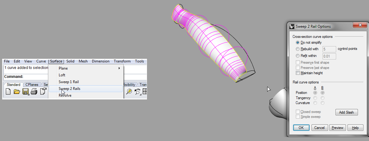
After a long process I managed to generate the figure, using offset tools, edge curves.
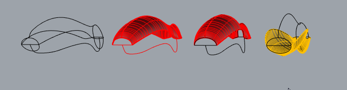
Finally the faces both internal and external are as shown in the figure, also as I need only a short face the figure in the middle
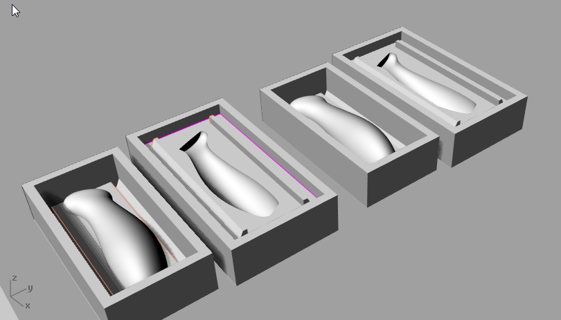
To generate the mold I must start to build under one face and with the tool Boolean difference, at the end the mold is of the following form, I leave it with the flat walls, but I read that it is better to leave the walls inclined. One advice from my instructor was to leave her without walls and place acrylic sheets around, a tip was also that she had very much in mind the size of the milling.
These were advances that I made in the past weeks but that were useful to continue with my final project.
First try to design the mold of my command but I had serious problems.
First I decided to make the mold as seen in the first image, but it was close to arrive the day of my presentation and by recommendation of my instructor use to move to the second design...
In the second design I only add the resin, I just have to remember to place enough release agent. In week 10 we were able to make the settings for a piece in the same way we repeated similar steps.
I made the settings for the roughing and profiling with the 6mm and 3mm milling cutters.
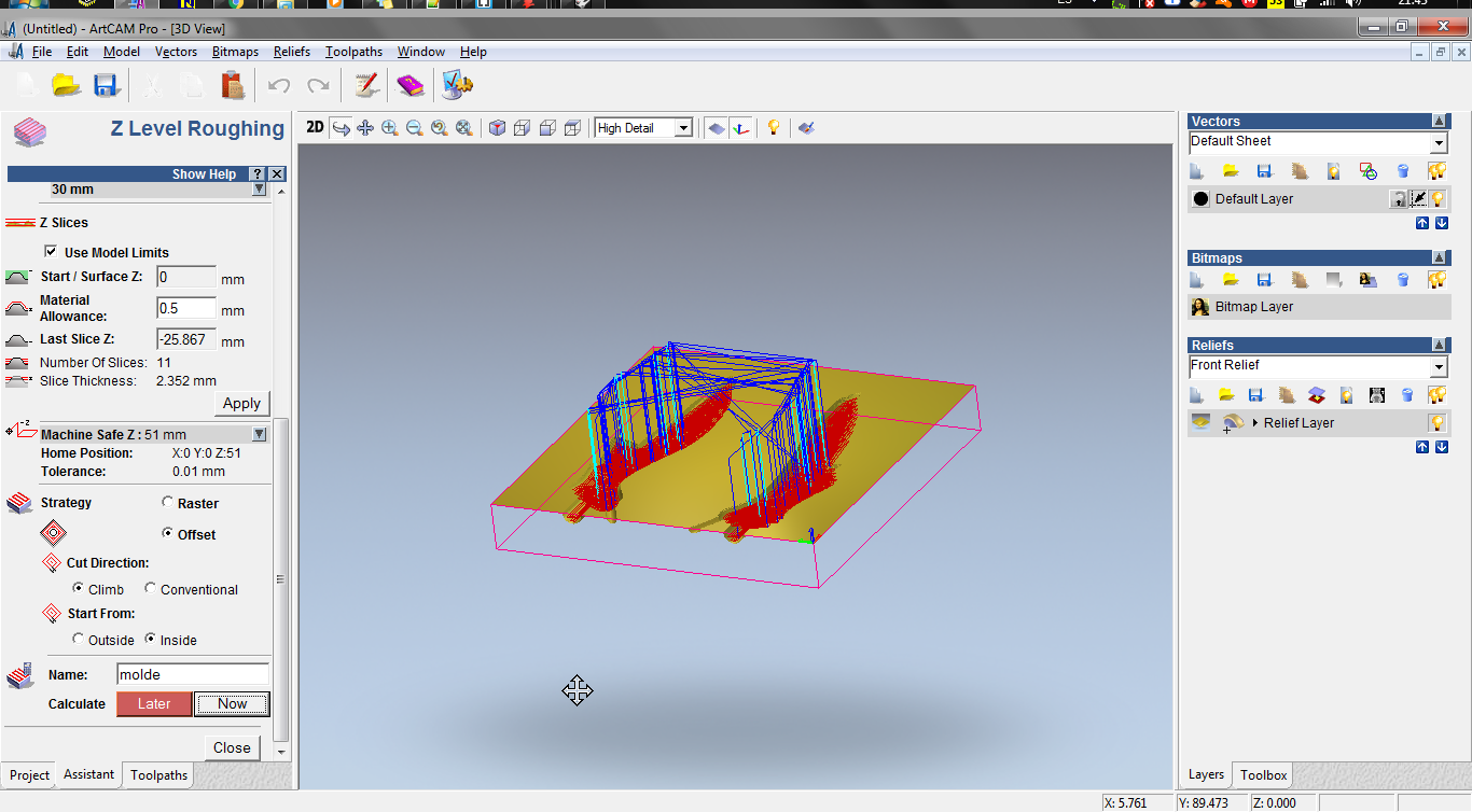
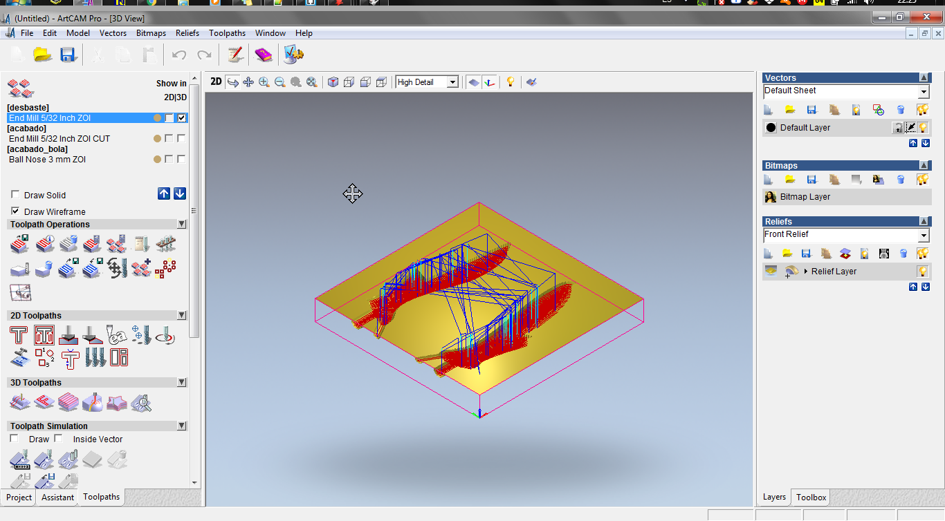
After about 3 hours of work I got a great result. the mold is ready
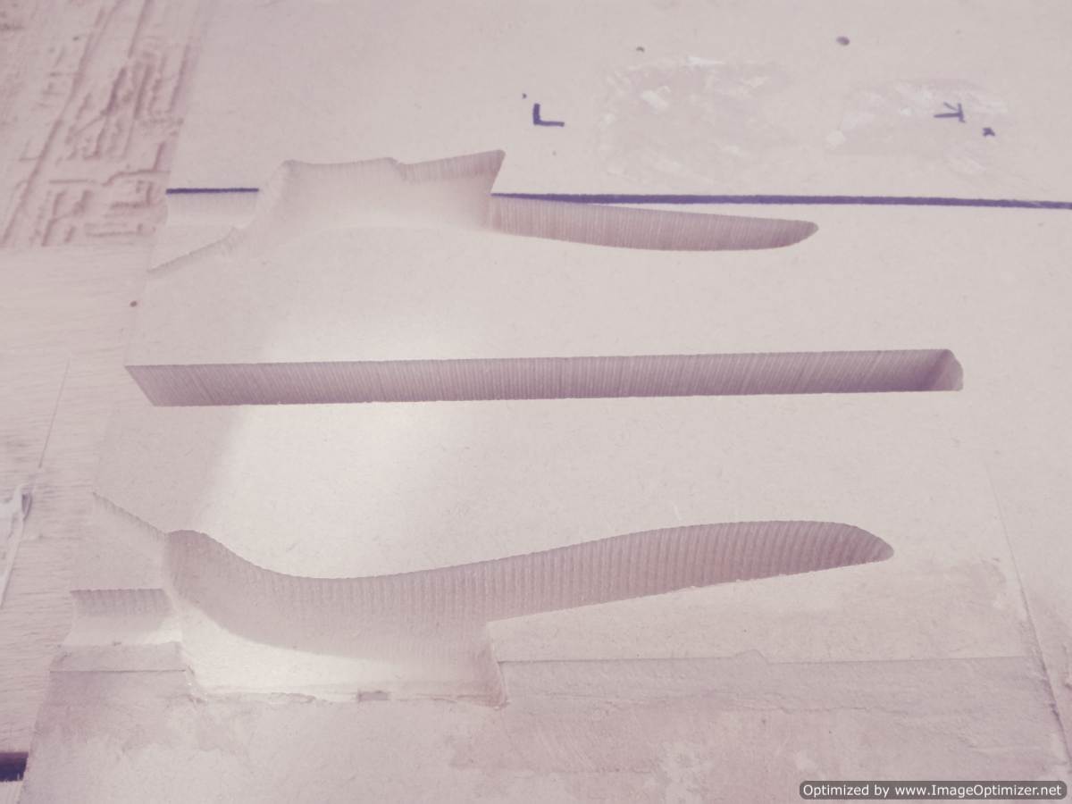
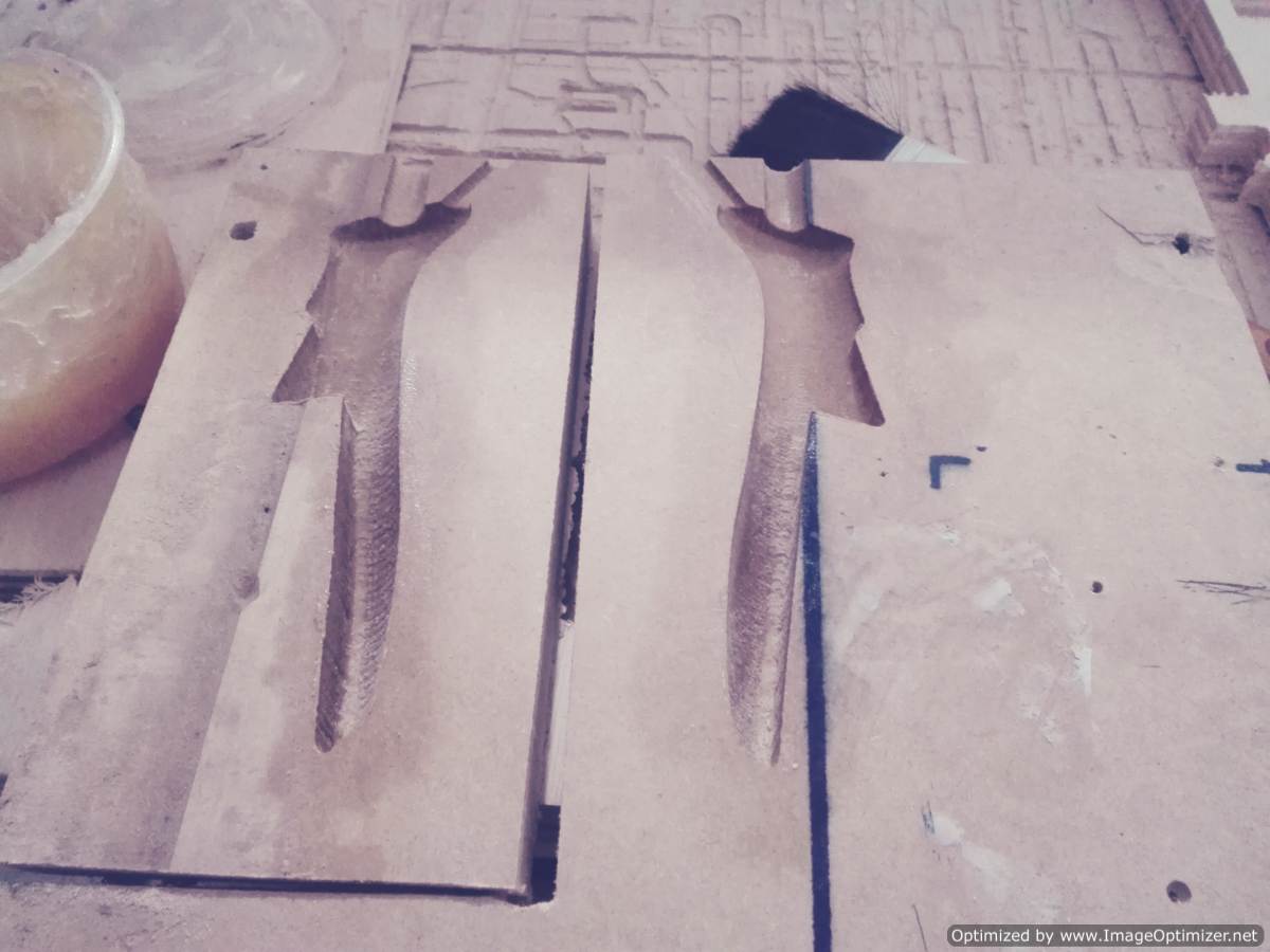
This time do not forget to perform the curing, or as they also name the seal of the piece, as my mold is made in MDF the recine can be absorbed. I seal the seal with petroleum jelly trying to cover the entire body.
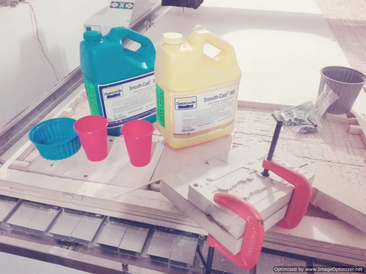
What materials I use for this process. As in week 10, I use the same Smooth resin. I like to use this resin, I can not go wrong when mixing. The week 10 we could see the safety sheets when working with this type of materials
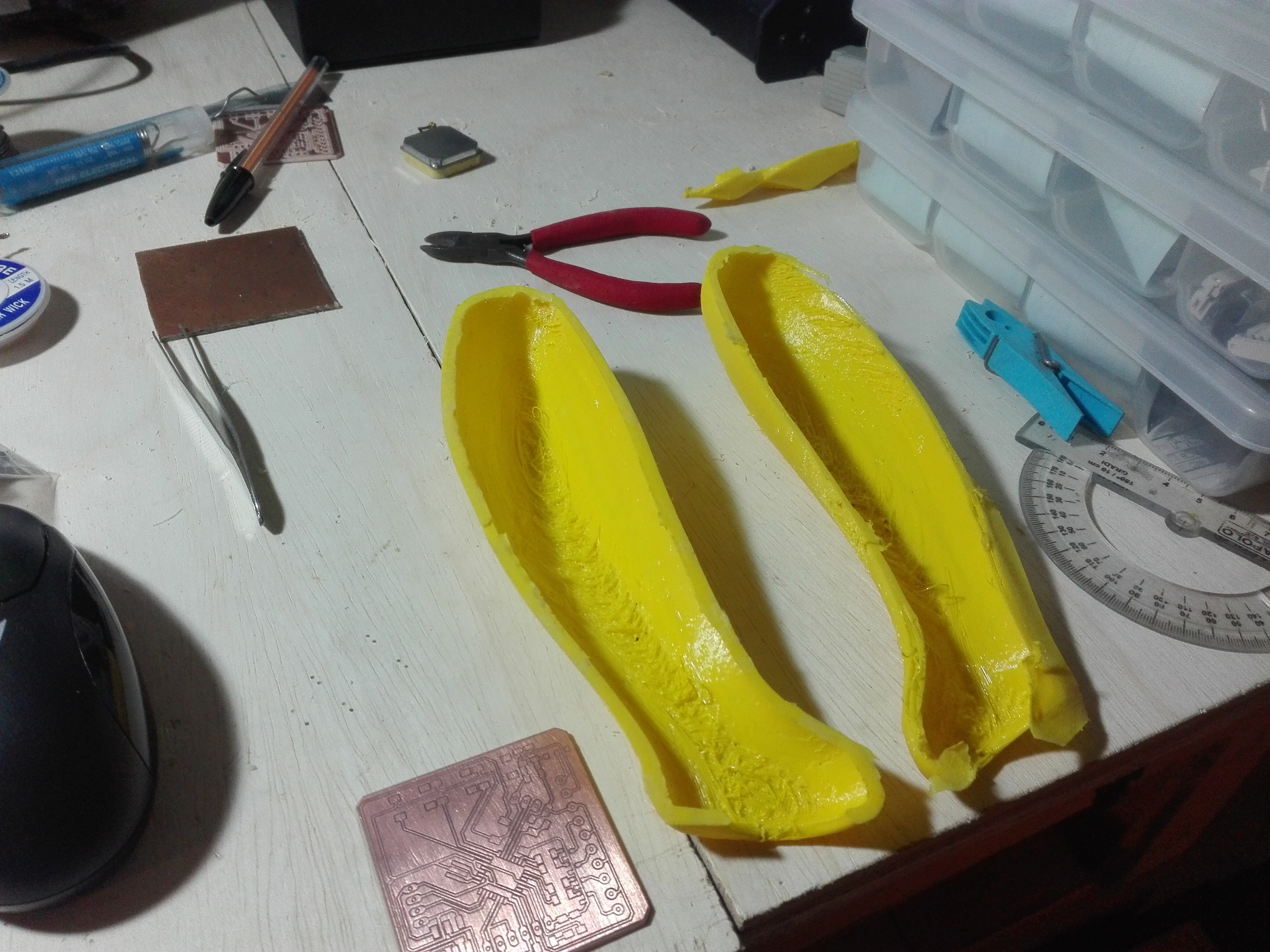
After an hour I went to get the piece and this is where I had my problems, I did not put enough mold release, the pieces were very stuck.
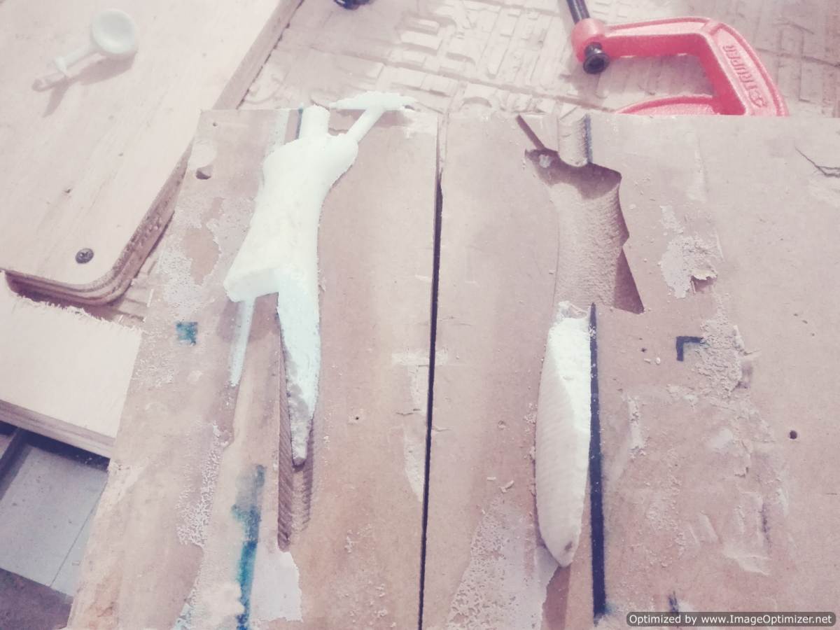
It was a big problem that I even broke the mold here, the evidence, I think this happened to me by omitting the step of making the rubber mold. As you can see the two parts are very close together, even the mold is damaged now tengp to do everything again.
I am determined to remove the piece in the previous way and I know that I am going to achieve it again, I will mold the molds and now I will seal the mold in a different way.
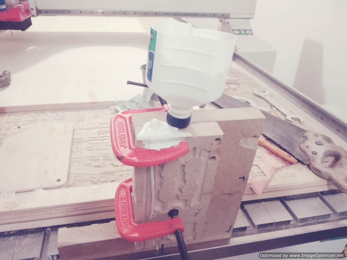
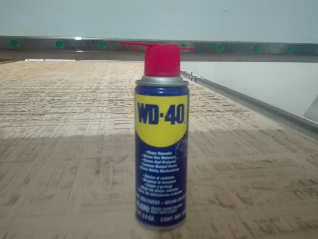
I'm going to seal the mold with the sealant used for the wood. At the same time use a sealant that my instructor recommended me and to finalize vaseline, if it is true they are many sealants. I hope that with this the final piece comes out very well.
.jpeg)
After making the seal the molds were very bright, I can see it.
.jpeg)
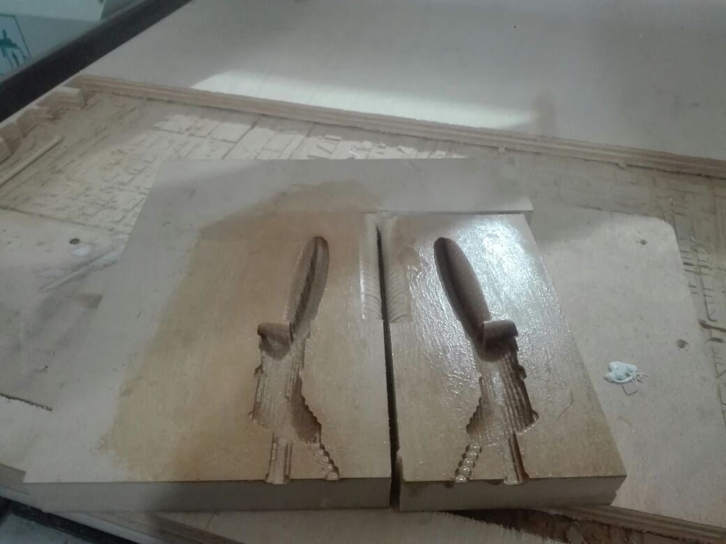
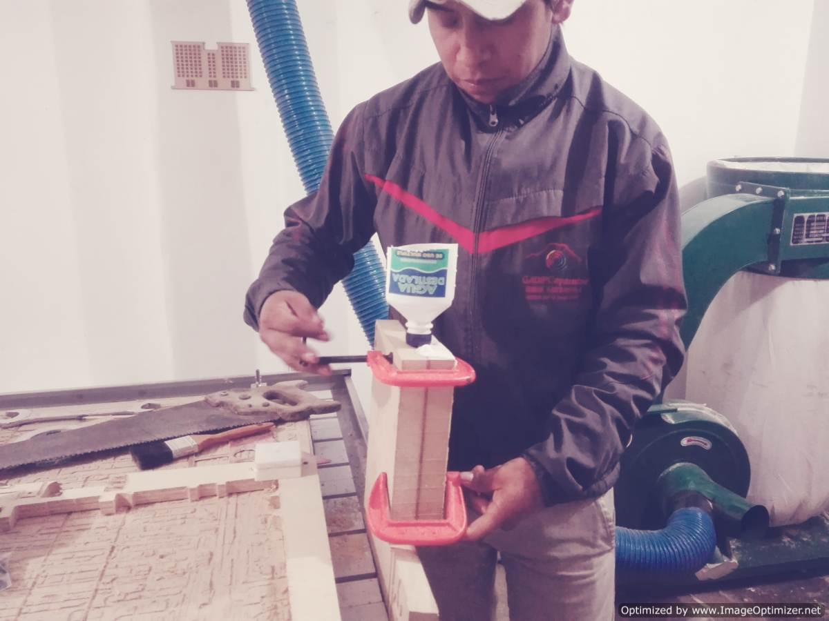
Again I made the mixture of the 2 compounds and after 1 hour I finally managed to get the mold that I was asking so much with a bit of difficulty but I did it. Now I can make molds, good simple molds.
.jpeg)
3D PRINTING
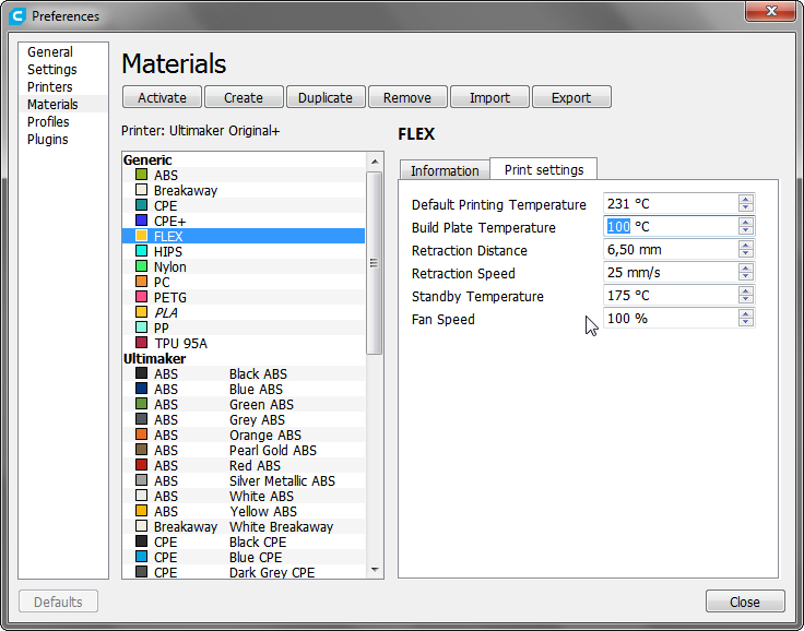
With the mold ready now step to design the cover. In the laboratory we have a very interesting material called FLEX filament and it will be very useful for my cover, this filament is flexible.
With the design of the mold, it was much easier to create the cover, in this case I only had to do in insset to the whole object. The offset that I place is 5mm which is enough for a cover besides that I assure that the majority of walls do not have very closed inclinations. By avoiding the inclinations I eliminate the supports and to make the imoresion comes out cleaner
The printer that we use is the ultimaker pro hacked and it does not have FLEX material in its list so I have to add it with the parameters recommended by the manufacturer.
Now I open the Cura software and I make the settings for printing.
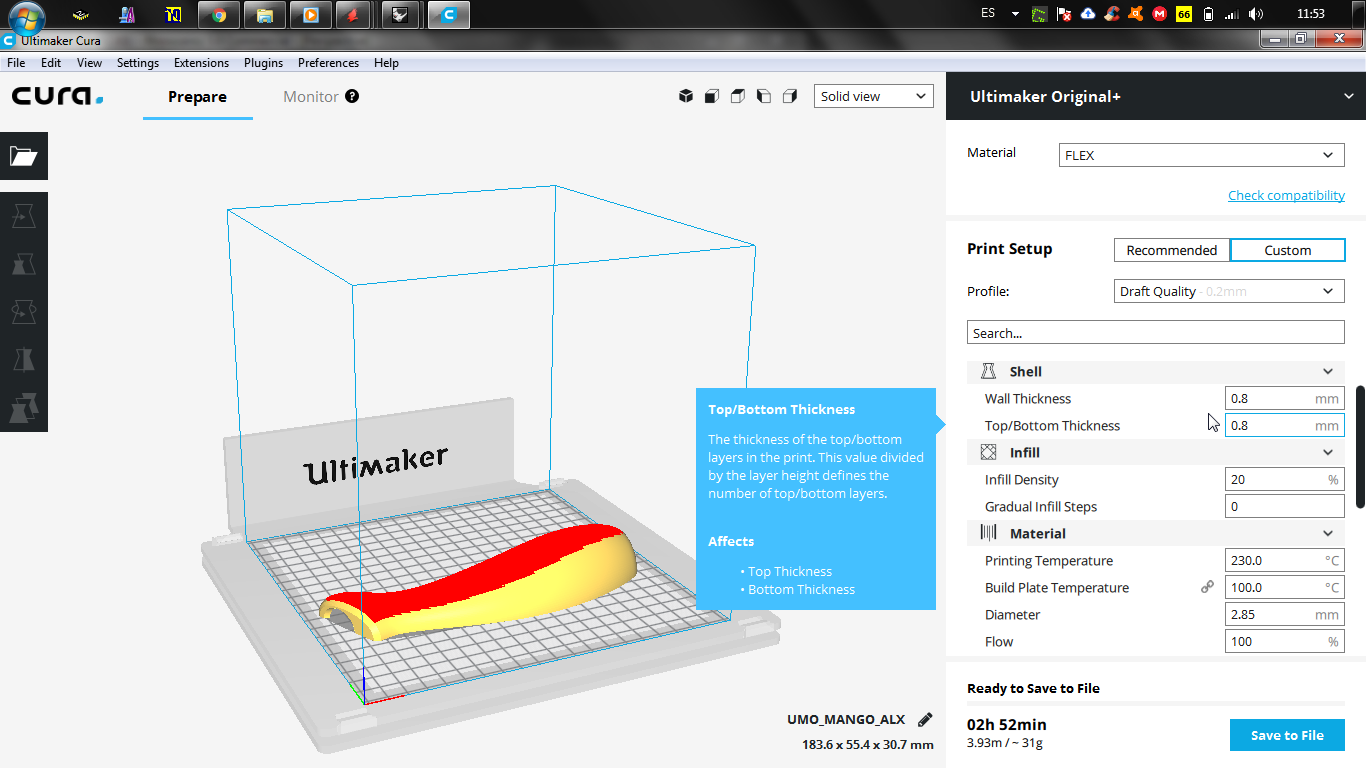
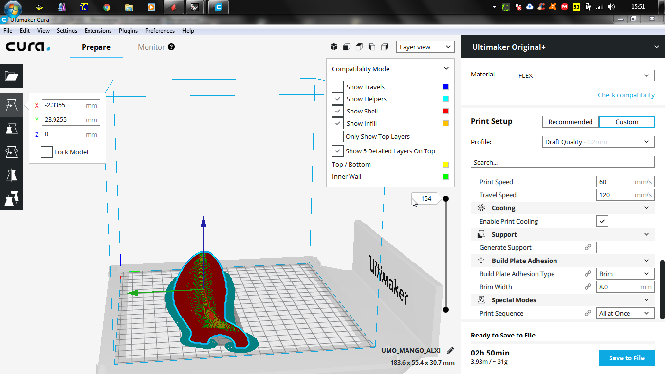
I can see that supports are generated but I'm going to run the risk of not placing them, I think the supports will be difficult to remove after the printing ends
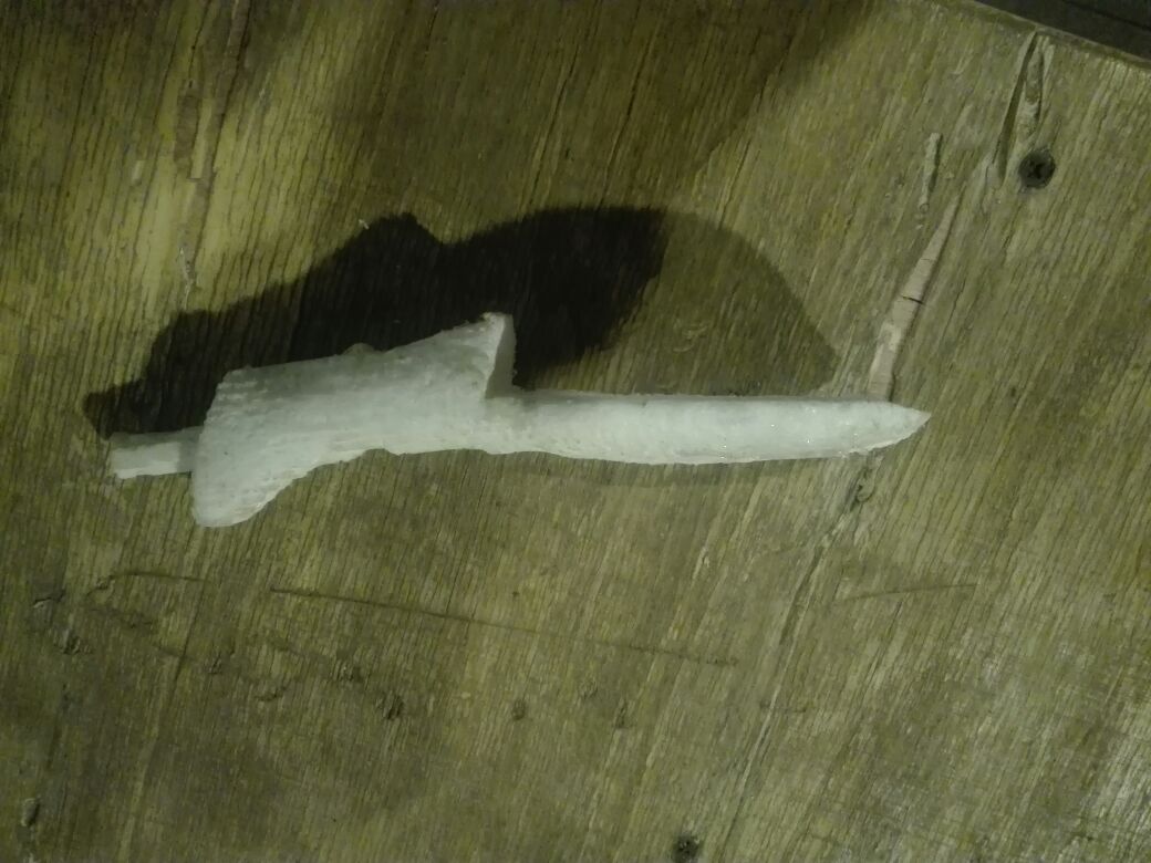
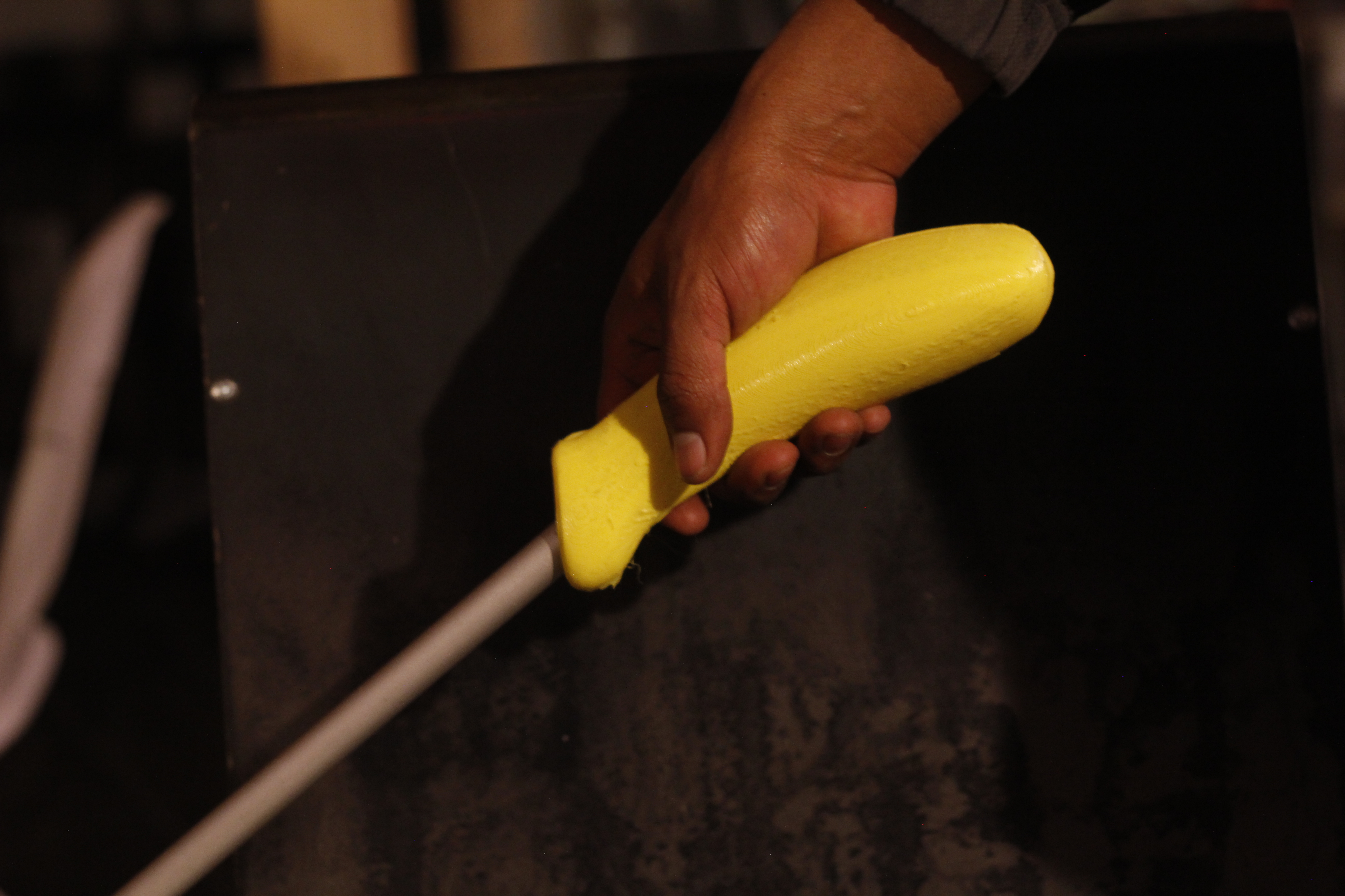
After 1 hour of printing I was able to make the pieces come out very well. Here are the results of my work.
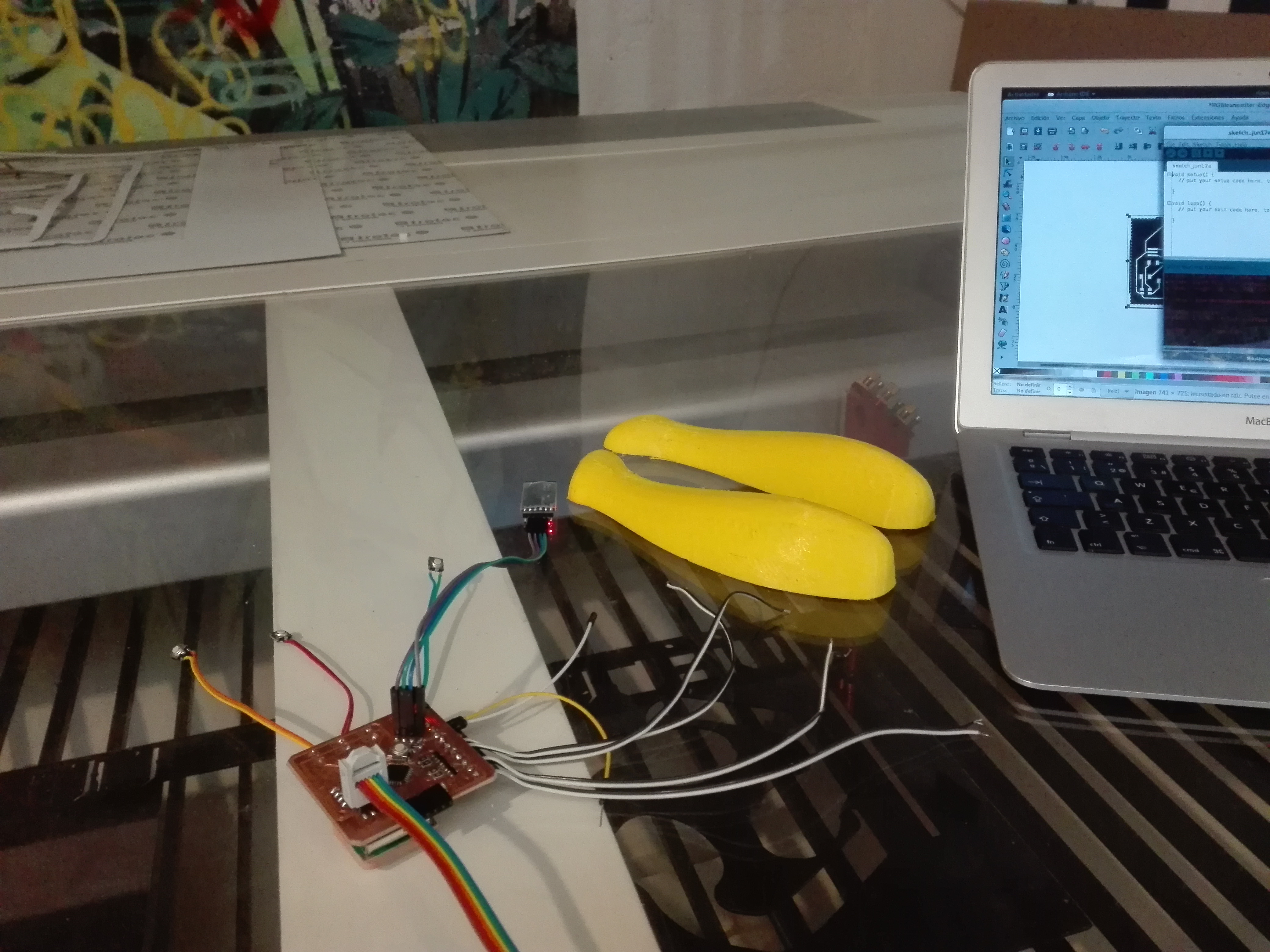
Now it's time to integrate the whole system
.jpeg)
Conclusions
* Trying to design a route tracking device is very complex, but I will not give up. I will continue with the process. The most important thing was that I managed to identify the logic to follow a line and give a warning if it goes out of this.
* A route has 2 points, the starting point A and the point B to finish, each point is a corner of a street, in space are the 2 points with coordinates, with this I create an equation, the equation is linear, to identify if it is outside the range of the line, the new point must satisfy the equation obtained, if it does not, a value is obtained if it is greater than 0 it deviates to the right if it is less than zero it deviates to the left.
* For the moment I managed to follow a street, but thanks to the words of a friend, "Big projects start with small things", I can say that my project has more to give.
* I have problems with the GPS because the error range is very high, in these weeks I receive the visit of MakerTour in my laboratory and we decided to visit the city of Cayambe, this city is well known for being half of the world under scientific sustenance, this visit It was very exciting, I managed to solve the most serious problem, I was able to talk to the person who works in this place and he mentioned GNSS technology.
The GNSS in the half of the world
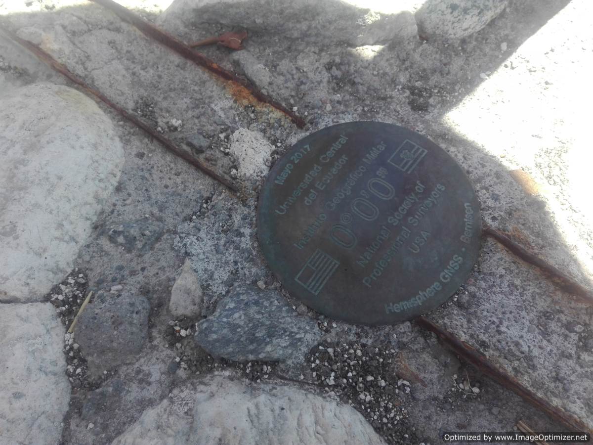
* The conversation spread and I was able to say that there are 2 ways to solve the problem in 2 ways, the only option is to use 3 GPS and triangulate this reduces the error to 1 cm, you can also use GNSS technology with which the error is decreases even more reaching 1mm this is very useful for my project and I can say that it works.
* To save the routes I find a great complication, I have a lot of information, I'm supporting with people who have developed mobile applications and I saw that they only take points to reduce memory space, following this example I verify if the previous values are equal to the new ones I only keep if there is a change in value
* My projects currently use modules, such as GPS and SD card reader. I want to pack these 2 components and make it smaller, it would be very useful to get a package and place it inside the remote, but with a smaller size
Opinion
I did the test with one of my cousins, only the device without the stick, my cousin's opinion was.
"When it changed direction it started to vibrate".
"I hope that when you finish your project you show me"
DOWNLOADS
Posted by Alex Tocagon. 2018

This work is under license of Creative Commons Attribution-NonCommercial 4.0 International.