INPUT DEVICES
In the same way I have to add an input device or a sensor to the microcontroller board that I have designed or in my case I will design a new one.
The learning outcomes:
Demonstrate the workflows used in the design and manufacture of circuit boards
Implement and interpret programming protocols
Individual assignment
1.- Measure something: add a sensor to a microcontroller board that you have designed and read it
Select the microcontroller and input devices
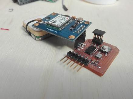
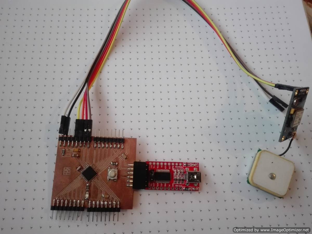
In my case, I selected a gps module to read the location, this is my input and I need the serial port, because the communication mode with the gps module is by rs232 communication.
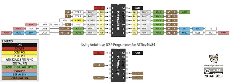
The location data is sent to the serial port, so I need a microcontroller that allows me to read serial data and send it to a terminal so I can visualize it. Attiny 45, despite being a very small microntroller, is very good, but it does not meet the needs for this type of reading.
The attiny 44 is a larger microntroller and has more ports of entry, so for me it is more appropriate to use this microcontroller. I include a button to start the process and to add a new input. All inputs can change except for the power pins, the oscillator and the program pins.
Electronic design with eagle
Eagle is a great design tool, I am more familiar and I can make the board faster, now I need to give more personality to my board. A technique to search in eagle more quickly is to place the name of the component to look inside asterisks example *led*
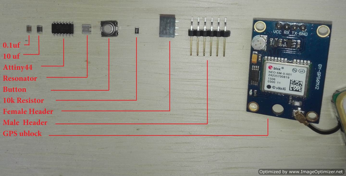
List of the components to use
- Microcontroller Attiny44
- Resonator 20Mhz
- Ftdi pin header
- Connector 1x04
- Resistors 10k Ohm
- Button
- Capacitor 10uf
- Capacitor 0.1uf
- Header to GPS
Ublox NEO-6M GPS
For this week's assignment, I decided to explore a GPS and the signal of a particular button. I will build a simple sensor and then I will explore a couple of topics, such as sensors with I2C interface and sensors with analog output.
Description 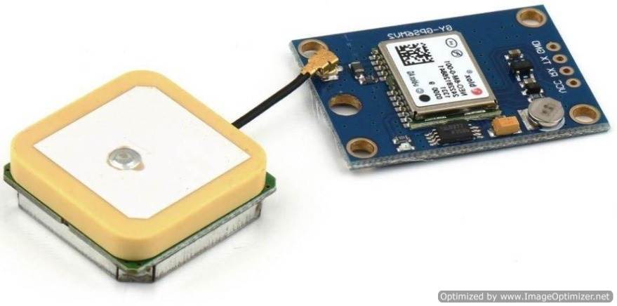
* Ublox NEO-6M GPS Module Aircraft Flight Controller
  Arduino MWC IMU APM2 projects robots NEW
* Ublox / u-blox NEO-6M GPS module with antenna and build-in EEPROM
* This module is compatible with APM2 and APM2.5,
  and EEPROM can save all your configuration data.
* Interface: RS232 TTL
* Power: 3-5v
* Baudrate default:9600bps
* Power supply :3V-5V
* Models: GY – GPS6MV2
* The LED signal lights
* The default baud rate: 9600
* Module size 25 mm x35 mm/0.98"x1.37"(inch) (approx)
* The antenna size: 25x 25 mm/0.98"x0.98"
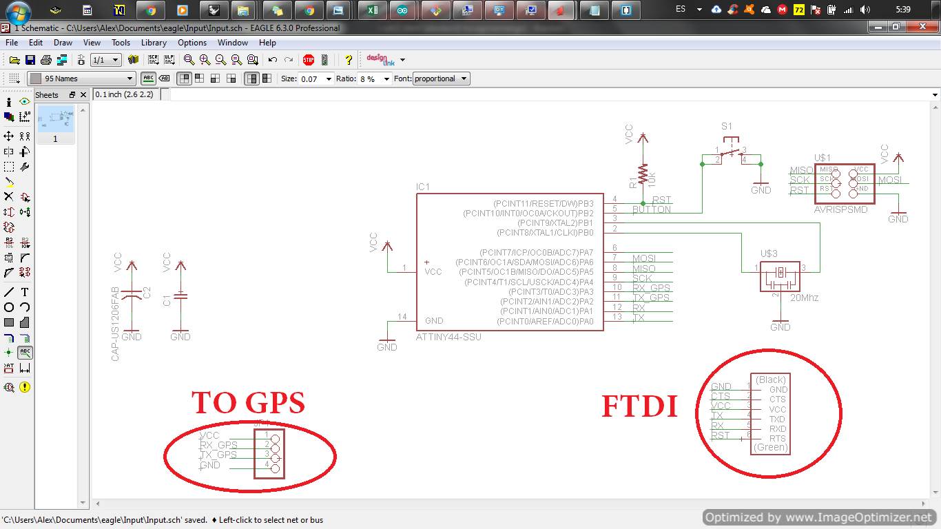
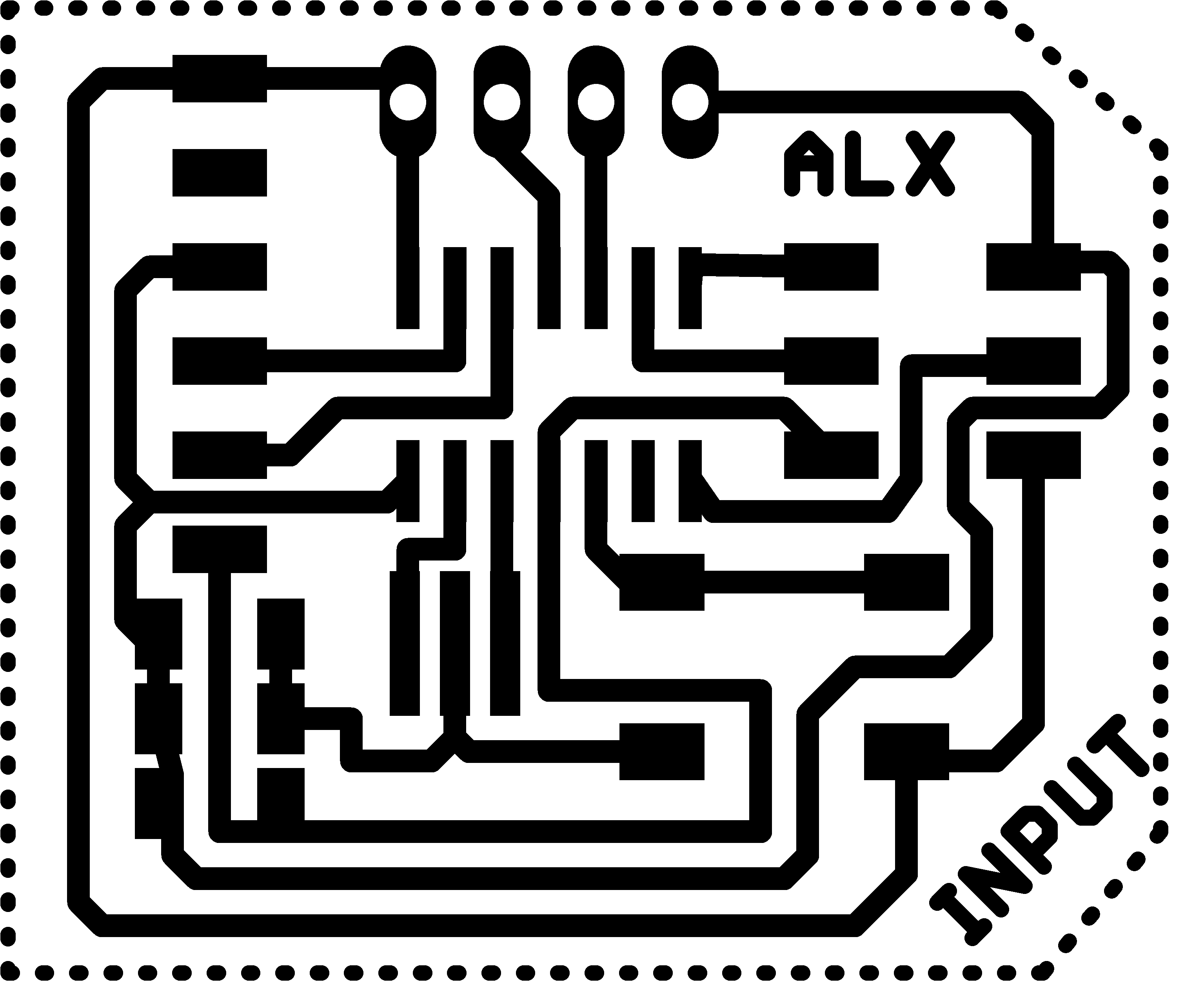
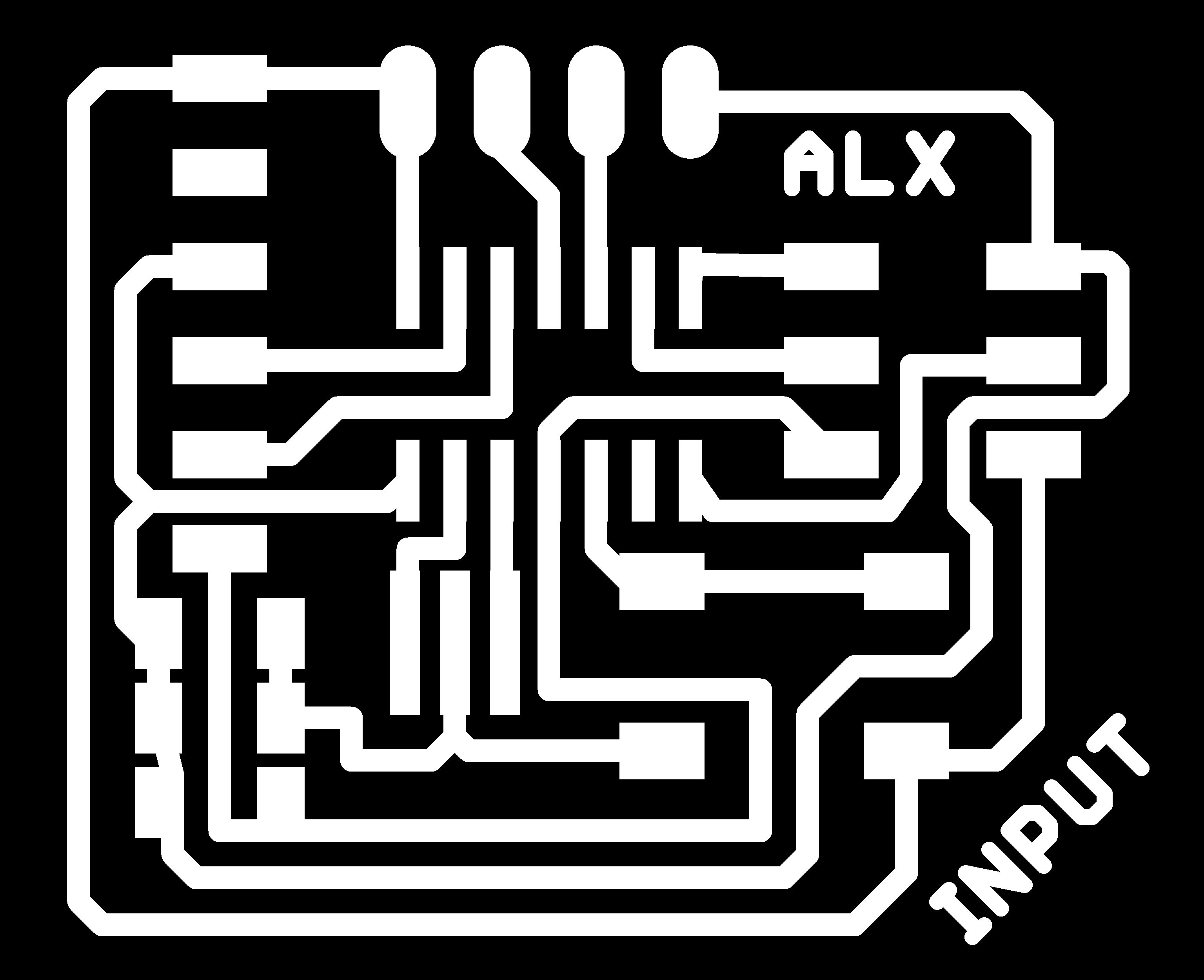
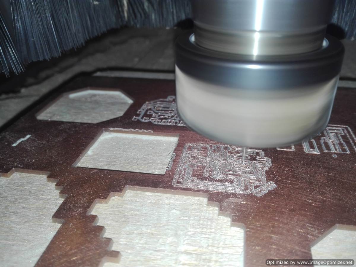
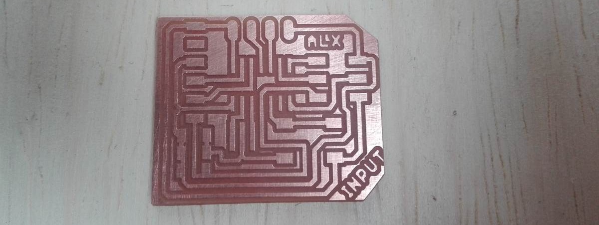
With the schematic ready now it's time to make the board
.png)
.png)
.png)
Edit Image and generate G-code
I go back to the editing of the images generated from eagle, now I put names to the PCBs for a better identification.
.png)
.png)
.png)

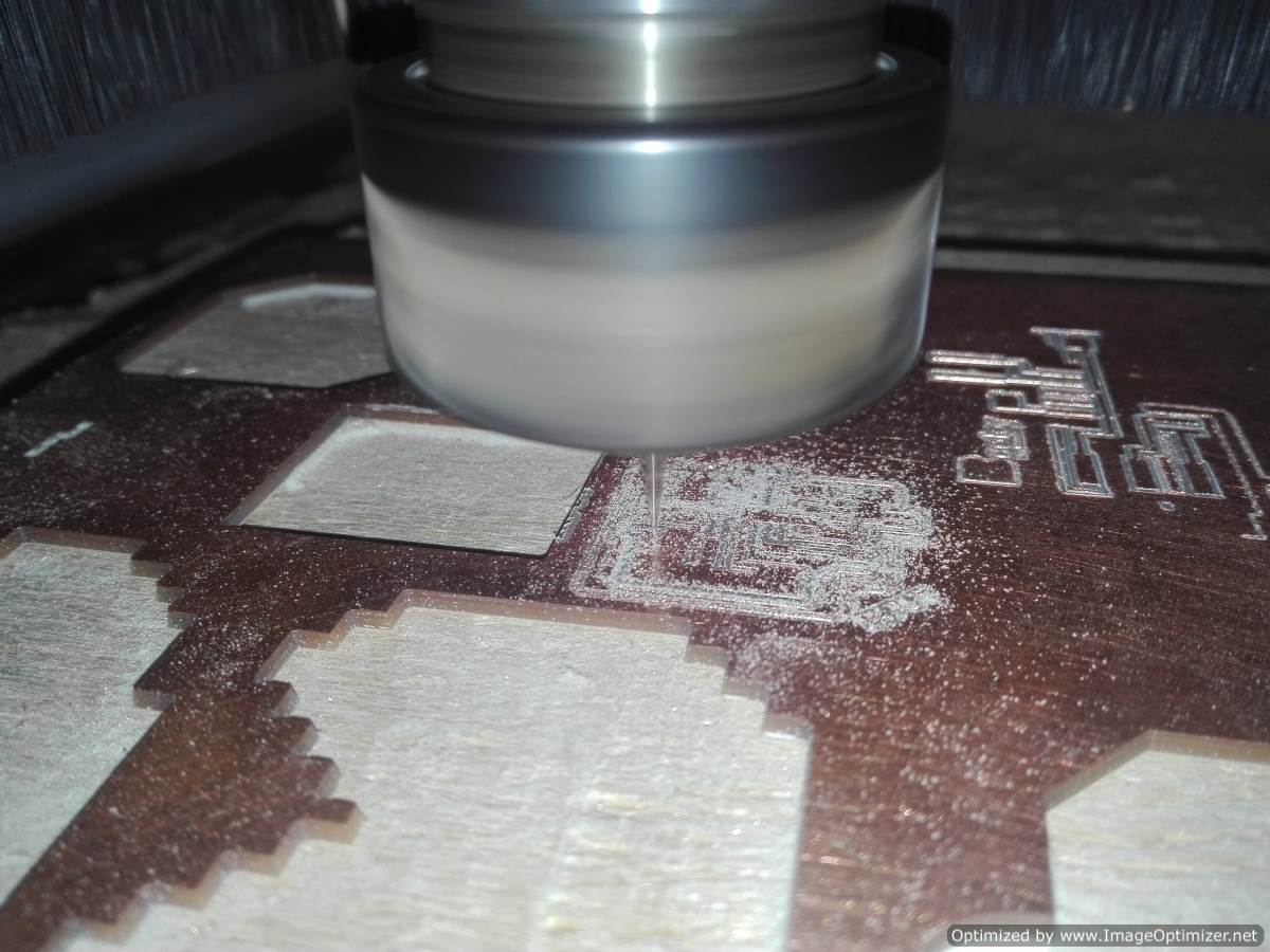
Milling and Electronic Production
With the files ready it is time to start with the milling, in my case I use the autoleveller software for a correct performance. This program has been very useful for the creation of PCB board. Together with the machine that LINUX CNC uses, they are a true marvel.
In this step have select the BOM (Bill of Materials)
Although we have named them before, it is very convenient to identify them according to their package.
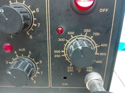
To weld the components use the captive at a temperature between 300 and 350 degrees centigrade
Programming
According to the data sheet of the microcontroller this has no communication port, but with the help of the Arduino ide I can create several virtual ports.
The data sheet helps me identify the resources that I can use, such as: communication ports, analog pins and digital input or output pins
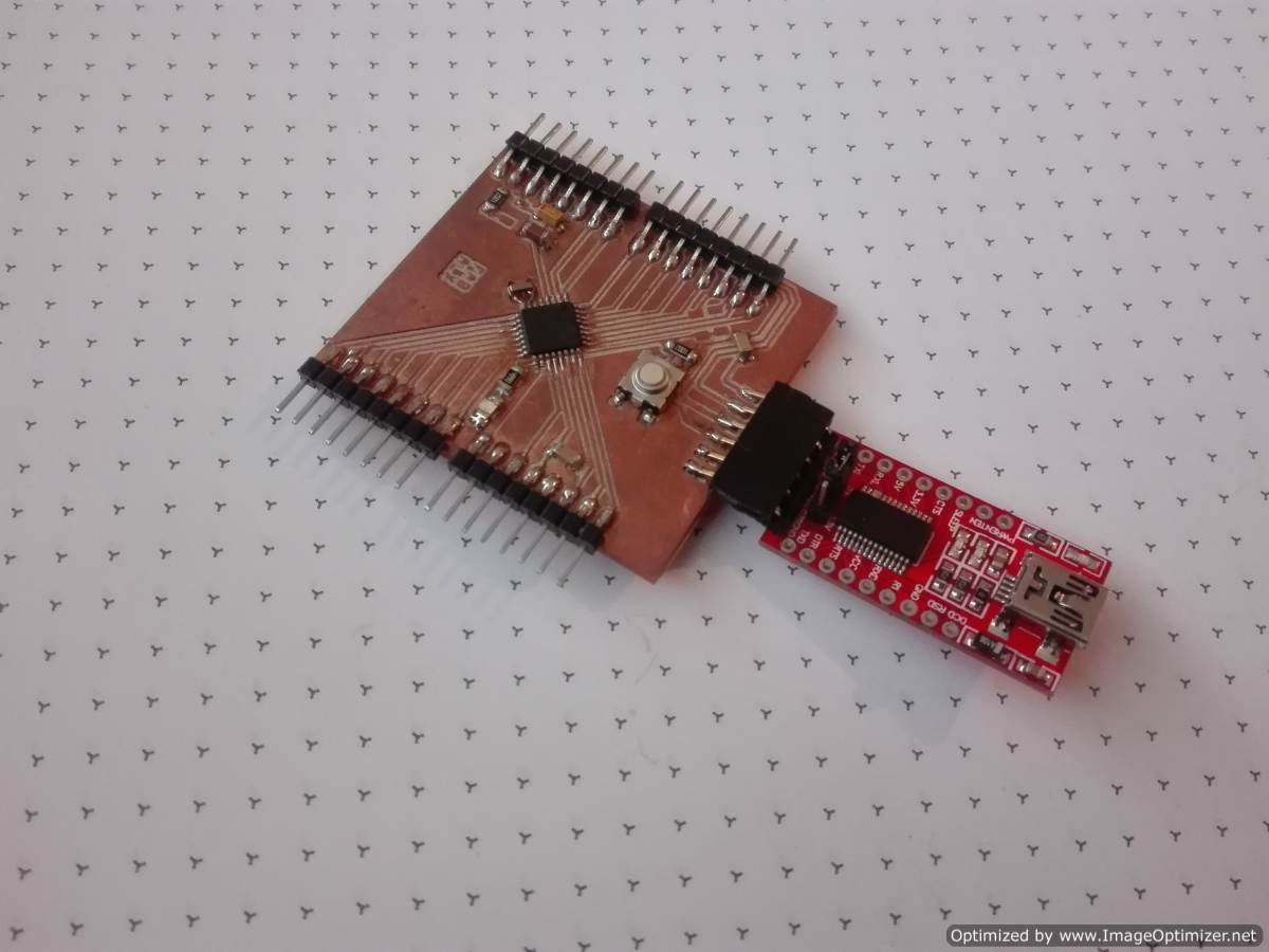
To start the programming, I select the software to programming my input PCB board. The first I select the Arduino Ide because I need create two Software Serial, one for comunicate the FTDI and other for comunicate the GPS ublock. I dont understand how to create two port serial in C code, but I think that in few day, i will achieve it
Well, now we are going to test our module by connecting it to our board through a serial port, it will be emulated by Software since we will use the Rx and TX to communicate with our computer, so we check the data that we receive by the GPS module and send it by the FTDI.
Next, I load the following code to our board, you can see that the SoftwareSerial library is used to emulate a serial port. (It is not necessary to install it, since it comes by default in our Arduino IDE).
This is a way of understanding the code by means of a flow chart each block represents a programming process.
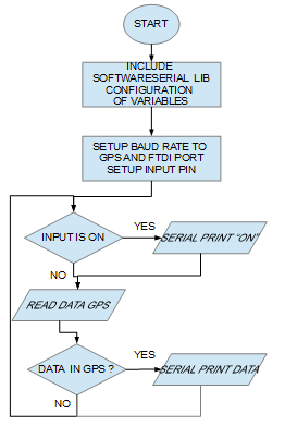
In a person program it is important to have certain habits to unify understanding. Write the code in a simple way so that the penguin can more quickly understand it. A good habit is to place specific comments of the instruction.
If you are already an experienced user create routine that save a repetitive code is very useful. Do not forget to put; after finishing the instruction, well this will depend on the language of programation that is being worked on.
Clear names to the variables and it is better to work better with lowercase, not to put extravagant or very long names that make it difficult for the reader. It is good to start the value of variables and counters at zero, in almost all languages it is necessary to do this step.
The decision instructions can help you to optimize the time, often the very continuous instructions take a lot of time. You can use the "switch" instruction together with the "case" instruction that allows you to search as your name indicates a case.
One option to use cycles is to use the instruction "for", this is an ideal for repetitive cycles is the same as "while" the difference is "for" the increase of the counter is automatic, with the instruction "while" need create the code to increase the value of this variable
In my case, use the arduino ide and to read the input data with the microcontroller you need to understand the instructions:
use analogRead (analogInPin) to read an analog pin
use the pinMode (pinnumber, INPUT) instruction to set the pin to read
use the digitalRead (pin number) instruction to read the pin, the data is digital.
#include "SoftwareSerial.h"

SoftwareSerial serial(0, 1); //PIN 12 AND PIN 13 ATTINY44  (RX,TX)
SoftwareSerial ublock(2, 3); //PIN 10 AND PIN 11 ATTINY44  (RX,TX) gps


bool newData = false;
unsigned long chars;
unsigned short sentences, failed;

void setup()
{
  serial.begin(9600);
  ublock.begin(9600);
  pinMode(8,INPUT_PULLUP);
}

void loop()
{

  if(digitalRead(8) == LOW)
  {
    while(digitalRead(8) == LOW);
    delay(10);
    serial.println("ON");
  }

  ublock.listen();

  while (ublock.available()>0)
  {
    int inByte = ublock.read();
    serial.write(inByte);
  }

  serial.println(" ");
  delay(1000);
}
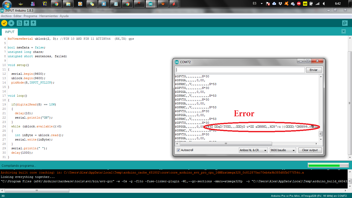
What our program does is constantly read the GPS module at a speed of 9600 baud which is the speed to ka which is configured by default our GPS module. The data received by the GPS is sent to the PC through another serial port in order to view them in our Serial Monitor. When we open our Serial Monitor, we make sure to configure it at a speed of 9600 baud. We can see the data we receive.
The data we receive in our GPS module follows the NMEA protocol, which are standard sentences for receiving GPS data. One of them and the most used are the $ GPRMC sentences, which have the following structure:
$GPRMC,044235.000,A,4322.0289,N,00824.5210,W,0.39,65.46,020615,,,A*44
I analyze the plot of this example and based on the NMEA protocol, I can determine the following variables:
- 232135.000 represents the GMT time (23:21:35)
- "A" is the indication that the position data is fixed and correct. "V" would be invalid
- 7807.2004 represents the length (78º 07.2004')
- N represents the North
- 0020.2135 represents the latitude (0º 20.2135')
- W represents the West
- 0.39 represents the speed in knots
- 65.46 represents the orientation in degrees
- 020615 represents the date (April 30, 2018)
As we have seen, from the data frame that our GPS module sends us, we can obtain several variables, the latitude and longitude being important for positioning projects.
.png)
.png)
.png)
.png)
.png)
.png)
Test
After loading the program on the card I had the following answer, when the serial input data is not recognized. I try to solve this problem
Group assignment
2.- Measure the analog levels and digital signals in an input device
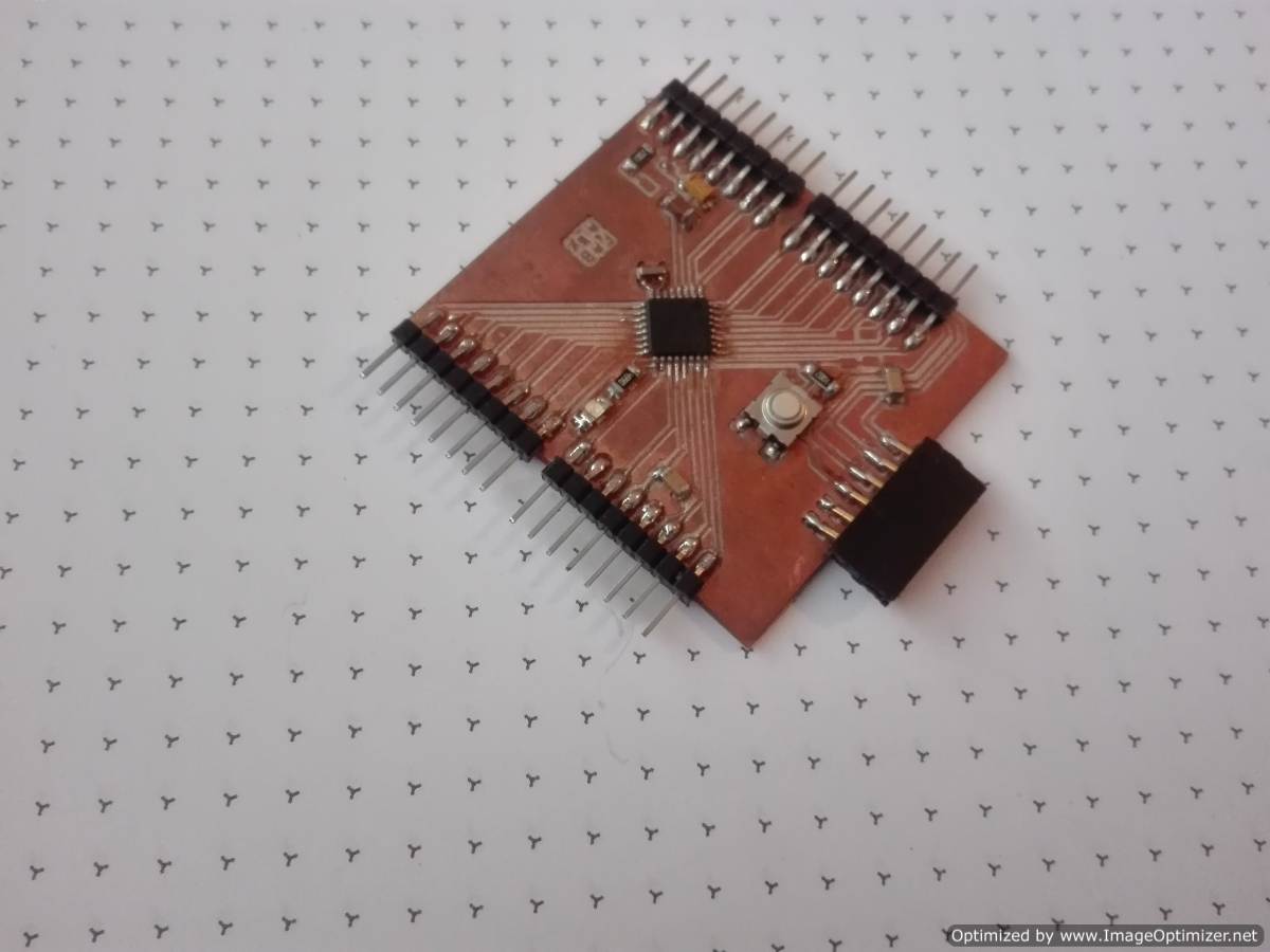
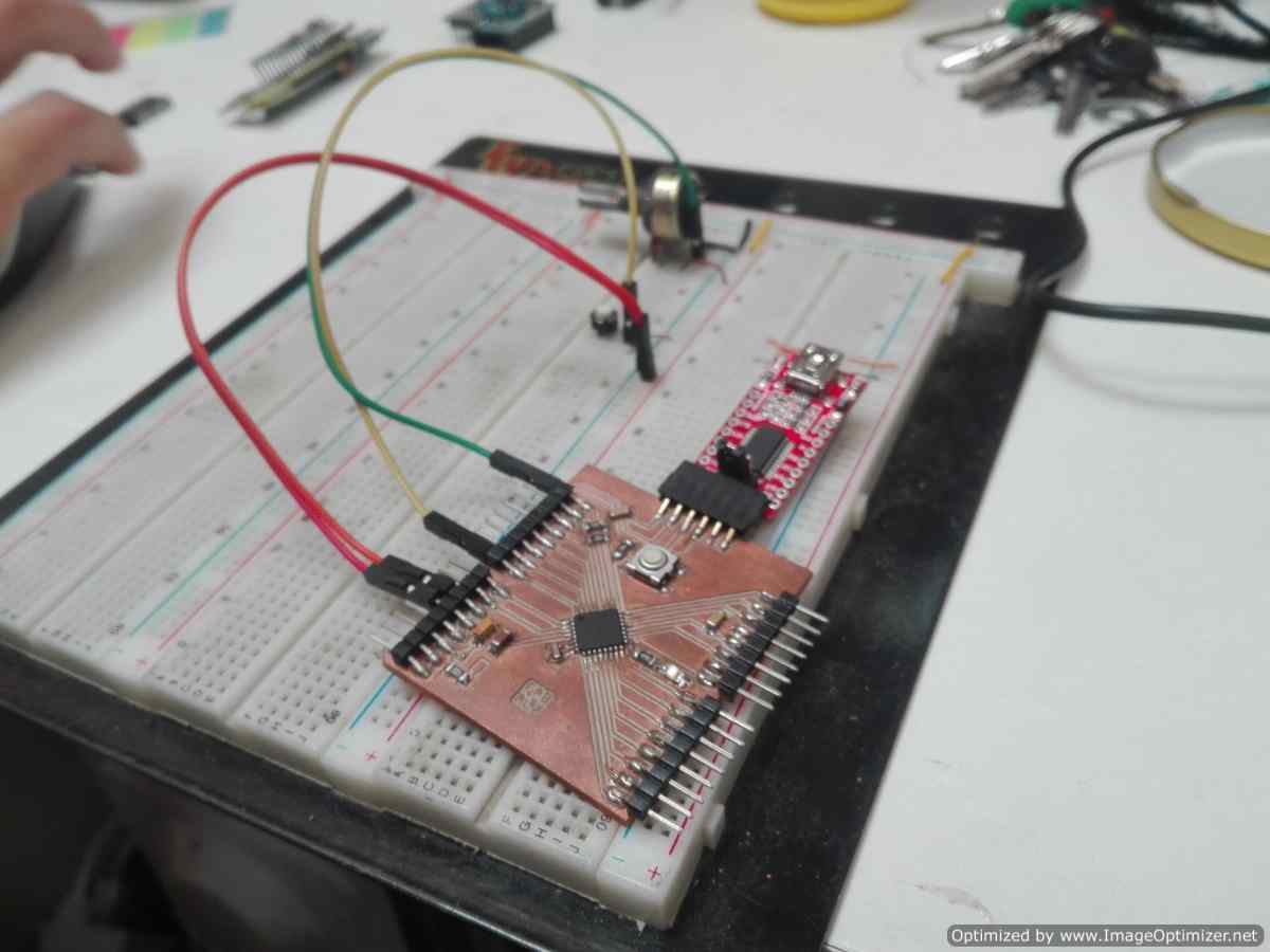
For this task I decided to use a different card, this card allows me to program with a USBFTDI, also in the arduino ide recognizes it as: arduino nano and arduino minipro.
First with this card I will try to solve the problem I had before, I want to identify if it has something to do with the microcontroller, sometimes it is very important to place an external oscillator, it could also be a reason for my problem, since my input card works with an internal oscillator.
Well I will use the TinyGPS library and the simple test example that the library brings, of course making the changes to work with my card.
.png)
.png)
.png)
.png)
.png)
.png)
.png)
.png)
I discovered something strange, the code I did before works well on this board, besides the gps I use delivers the communication data, but it does not deliver the position values, in the test I did it took about 15 minutes, I read that it happened that the gps with establishes a connection. With this plate and a breadboard I'm going to do some tests with several sensors
For the assignment of the group that decided to test with 2 sensors, the most common example is the use of Botton and potentiometer, to detect if a door is open or closed.With the button is simple the information it receives is ON / OFF in other words, the door is open or closed. it only delivers 2 types of signal.
But in the potentiometer it is totally different, an example is: if the potentiometer incorporated in the hinge, the information is variable, the door is open or closed, but also the door is half open or half closed, translated to percentages is from 0 to 100 %
For this I use My FABALX and the test plate because it is faster to do the test.
In the arduino ide, I look for the example of analoginoutserial and the button after combining the 2 codes I upload them to my FABALX
const int buttonPin = 2;     // the number of the pushbutton pin
int buttonState = 0;         // variable for reading the pushbutton status
const int analogInPin = A2;  // Analog input pin that the potentiometer is attached to
const int ledPin =  13;
int sensorValue = 0;        // value read from the pot

void setup() {
  // initialize serial communications at 9600 bps:
  Serial.begin(9600);
  pinMode(buttonPin, INPUT_PULLUP);
}

void loop() {
  // read the analog in value:
  buttonState = digitalRead(buttonPin);
  sensorValue = analogRead(analogInPin);
  Serial.println(sensorValue);
  if (buttonState == HIGH) {
    // turn LED on:
    digitalWrite(ledPin, HIGH);
  } else {
    // turn LED off:
    digitalWrite(ledPin, LOW);
  }
  delay(2);
}
You can see how the LED turns on and is paid depending on the pulse of the button, while in the serial plot of the arduino ide you can see the value of the potentiometer.
CONCLUSION
- Most sensors and input devices deliver a signal that can be read by the microcontroller.
- There are several inputs devices that are not strictly analog and that use a communication protocol, among them I found accelerometers, GPS, these 2 communicate through I2c and serial port
- Like the microcontroller, each input device has its respective datasheet where we can consult the sensor information.
- My GPS has the error of 1 meter, this is the several problem for my project.