4. Computer controlled cutting
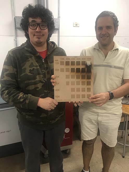
This week I started working with the assignament in group. It was done with my partner Luis Perez Tolentino.
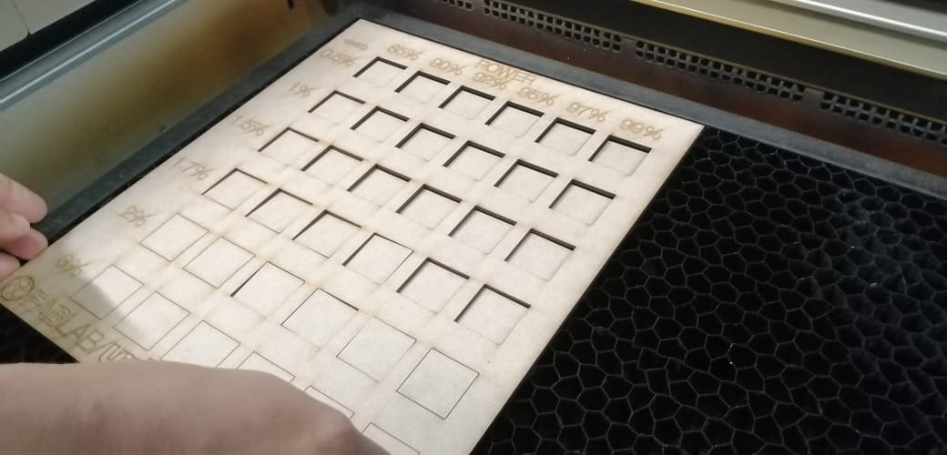
TASK 1: Building a chart of Power vs Speed
First we decided to build a chart in order to compare the power of the laser beam with the speed in MDF of 3.18mm.
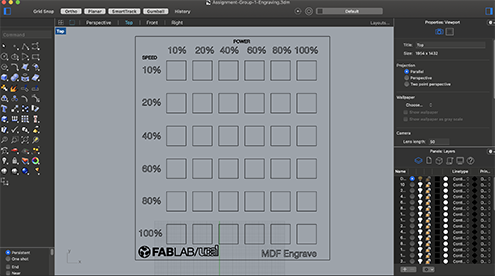
We draw the chart in Rhinoceros.
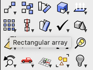
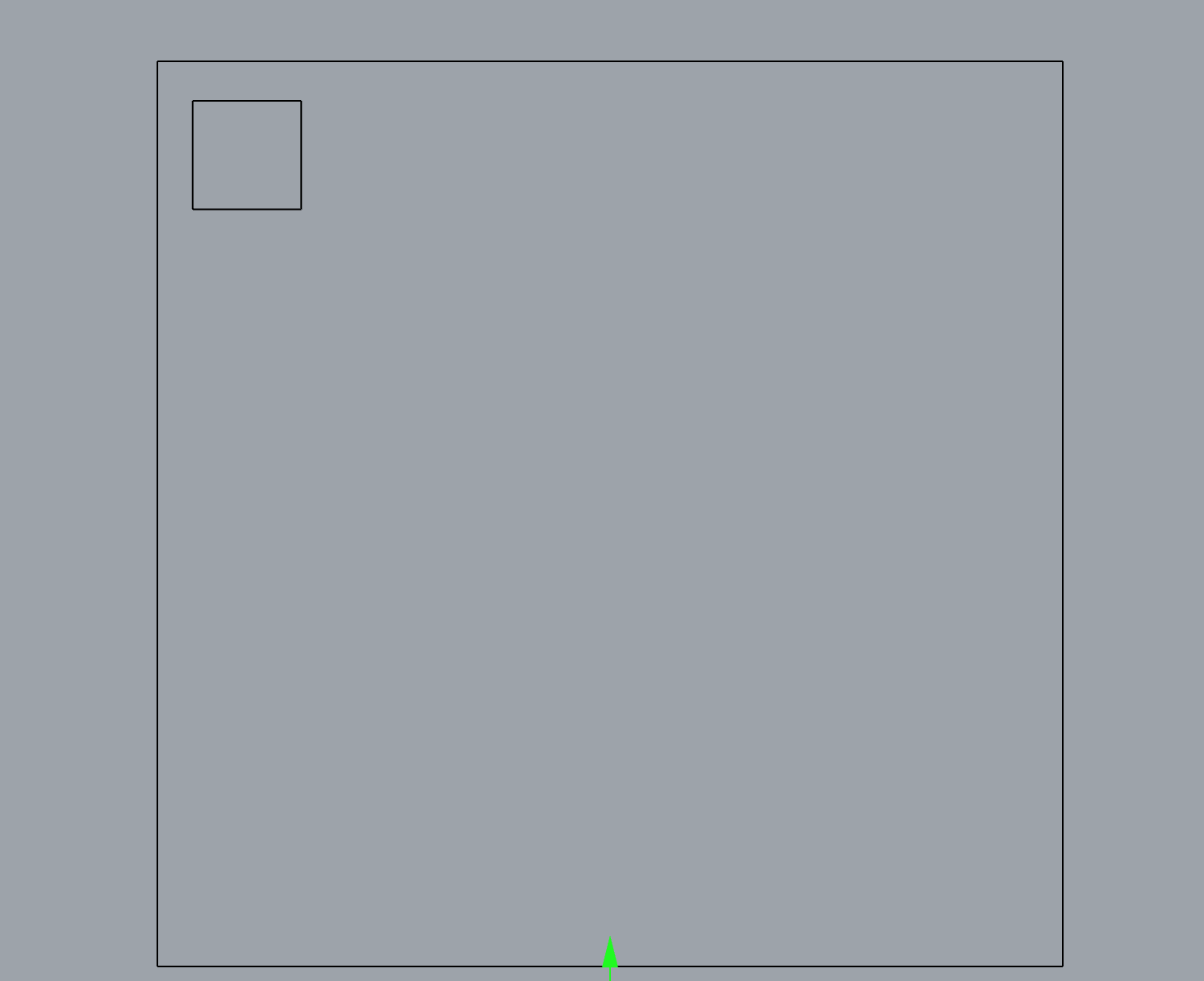
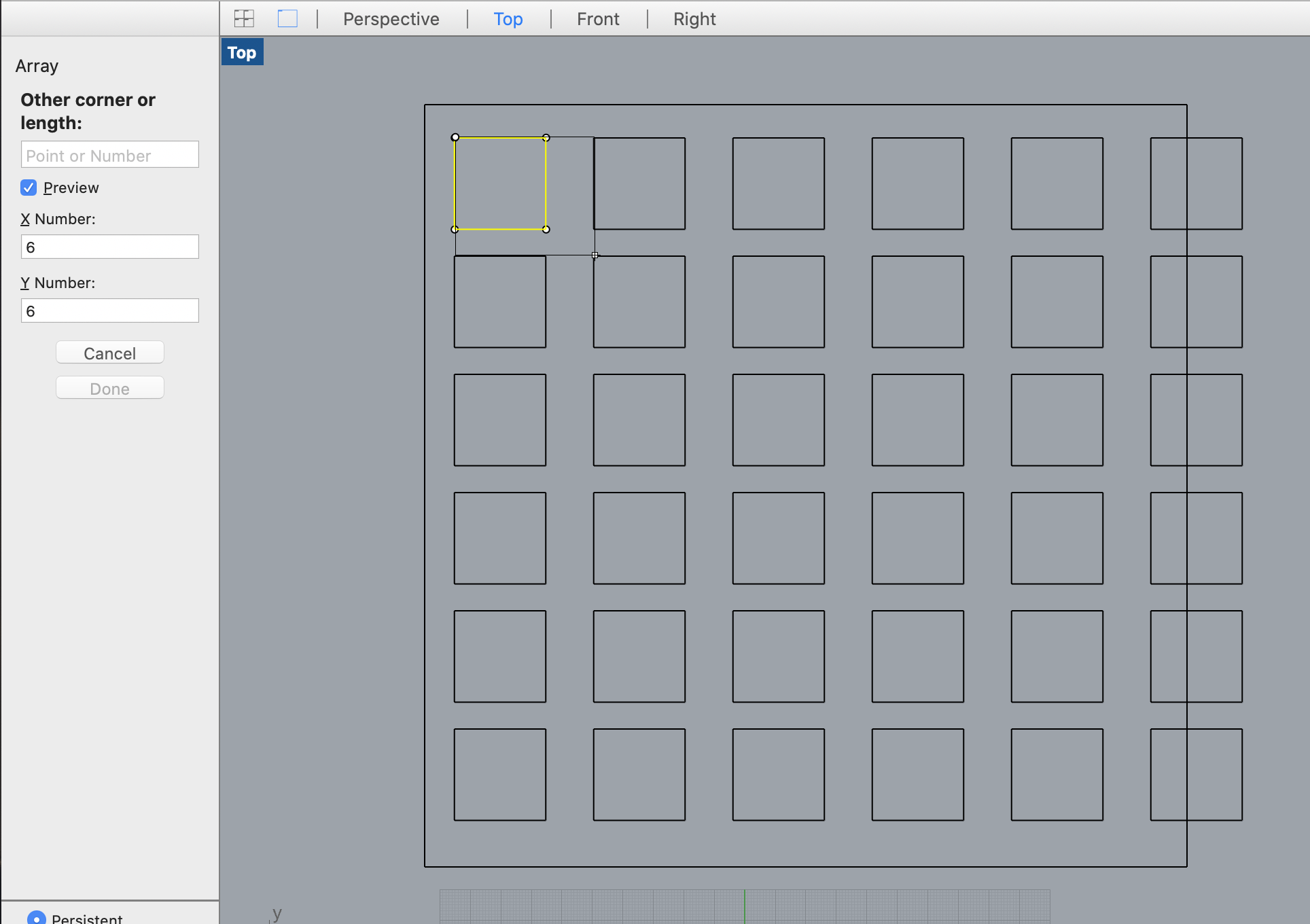
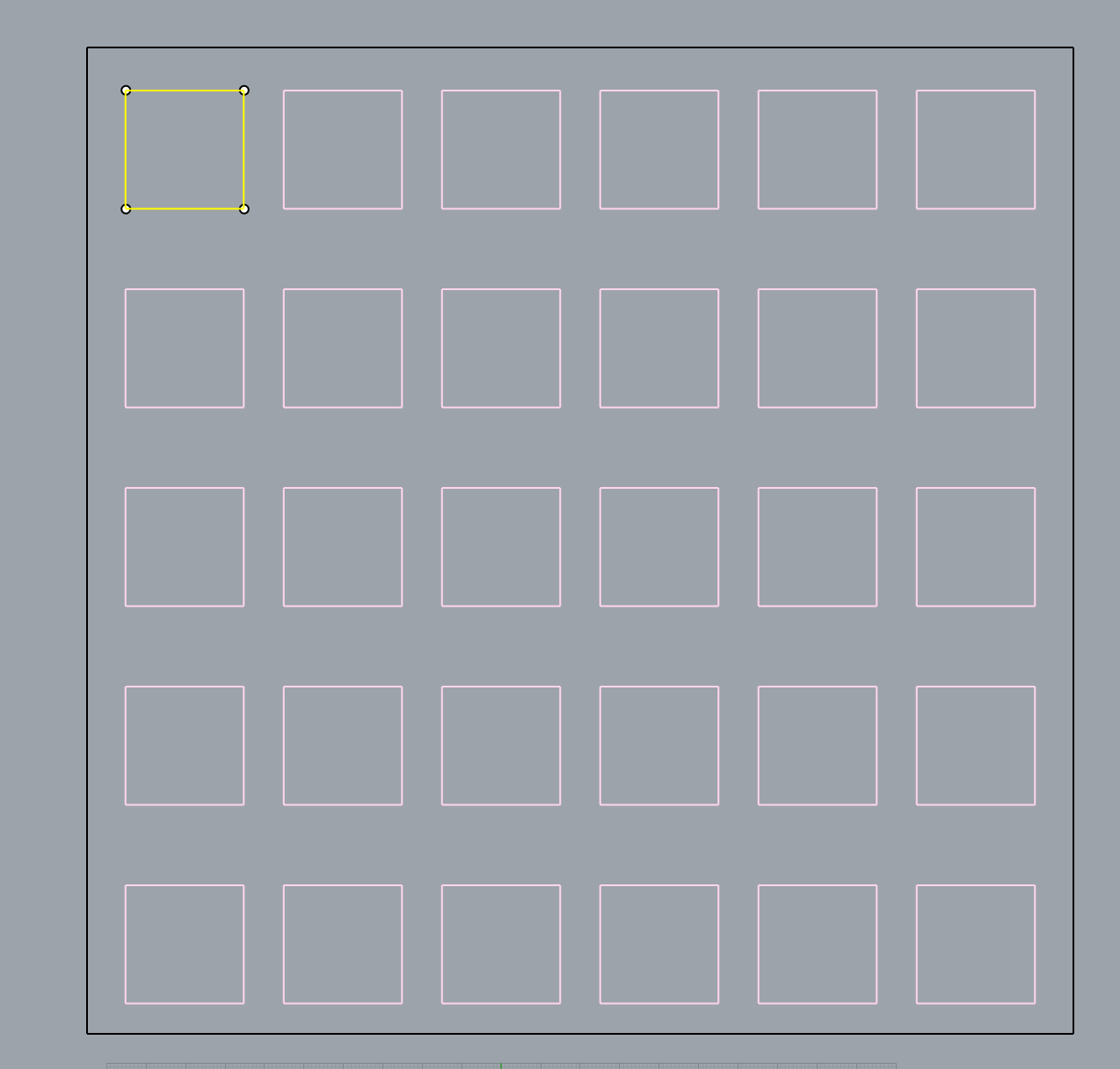
First we use the command rectangular array due to the squares as shapes chosen.
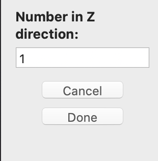
Then we write the dimensions of the square in X axis, Y axis and because it is a 2D drawing, Z has to be 1.
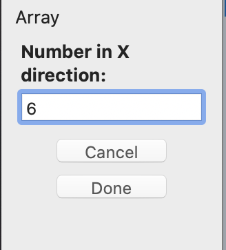
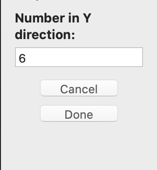
Here the first square. Then we multiply it by 36 because we use 06 columns and 06 rows. We establish the columns for the power ranging from 10% to 100% and the rows from 10% to 100%, both parameters for engraving.
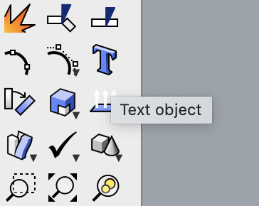
After we select to add the Text.
Here a link with the Rhino version.
The next step was to prepare the drawing to be cut with the Trotec Laser. We have to hatch the squares that are going to be engraved, by creating layers. Each square is going to be cutted at a specific power and speed, so we have to create 36 layers one for each square. After that we have to add the layer for cutting the border and a layer for the text.
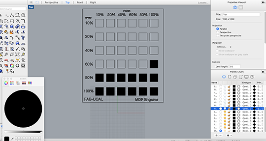
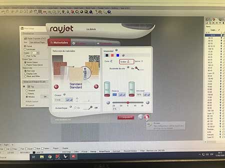
Then we have to setup the information in the Trotec laser cutter. Here we learn to use different color either for cutting, marking or engraving. We write the first power which is 10% and speed to 10%.
Calibrating the Trotec Laser: First I turn the laser cutter and the filter on and then we start to focus manually.
Trotec Laser calibration from Manuel Corrales Arana on Vimeo.
After, we gave the order to the laser machine to start doing the marking process and it did it well. Then we start the engraving process but something went wrong. We realize that we use the template model of cutting for engraving.
Here we suggest to focus in the work. It was night and probably the tiredness was playing tricks on us. So, we start again using another 3.18mm MDF.

We correct the parameters of the speed in Rhino by changing the numbers and then we did the same with the parameters in the trotec software before we sent the info to cut.
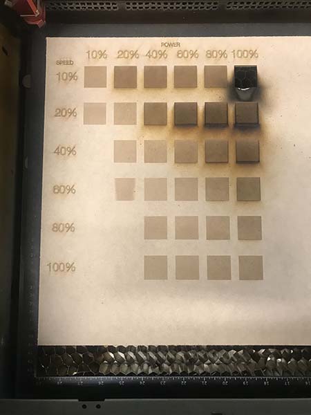
When the laser cutter start to engrave, we notice something really strange, fire. Using a power of 100% and a speed of 10%, during all the engraving process, fire appears and at the end we noticed that the square has being gone.
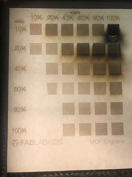
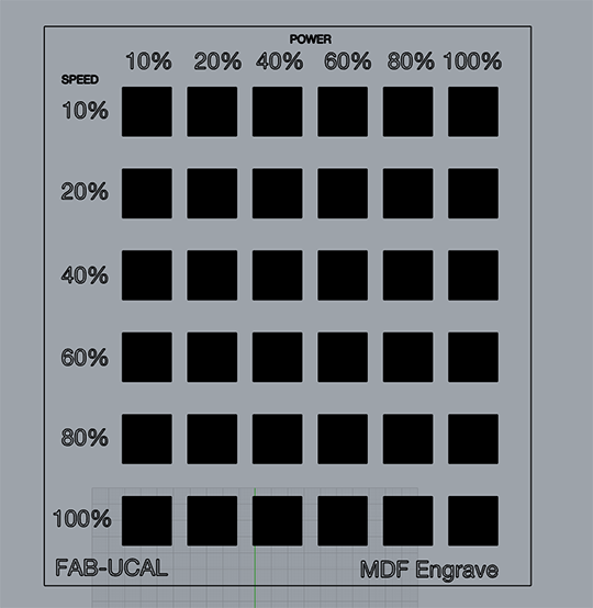
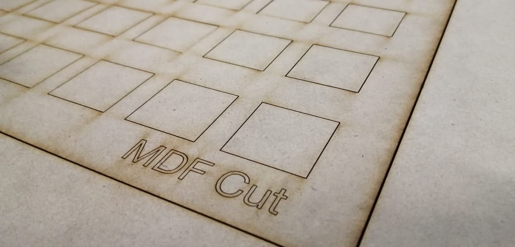
After completing the cutting work, we finally have the MDF table with the different depths of engraving.
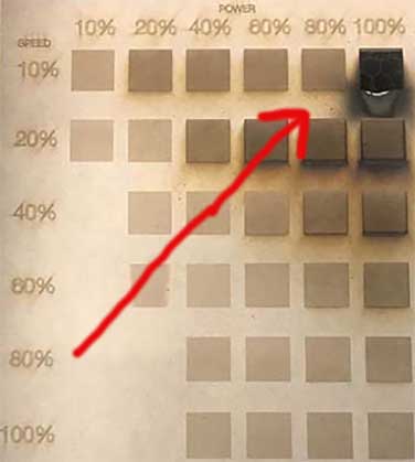
Personally this work was very interesting and i hypothesize that the relationship between depth and power will increase directly proportional but in the first line where the speed is 10%, the correlation is not as expected when the cut runs from left to right, from less poer to high power. At this speed the change in depth between 80%, 90% and 100% is drastic. Where as a slight depth is noticed in the square of 90%, it passes to a depth of the MDF width by vaporizing the square.
Cut
Group work
After engraving we continue to work with the cut process by changing the MDF table and the parameters in the software. We use:
| POWER | 85% | 90% | 92% | 95% | 97% | 99% |
|---|---|---|---|---|---|---|
| SPEED | 0.5% | 1.0% | 1.5% | 1.75 | 2.0% | 3.0% |
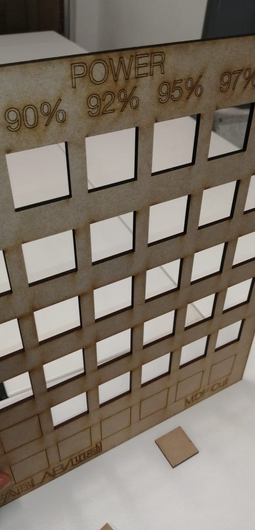
Then we test some of the squares to notice the difference in the mark left in the interior of the cut of each square. In the ones that uses more power there is a black spot.
Testing with Laser Cutter from Manuel Corrales Arana on Vimeo.
Laser cut from Manuel Corrales Arana on Vimeo.
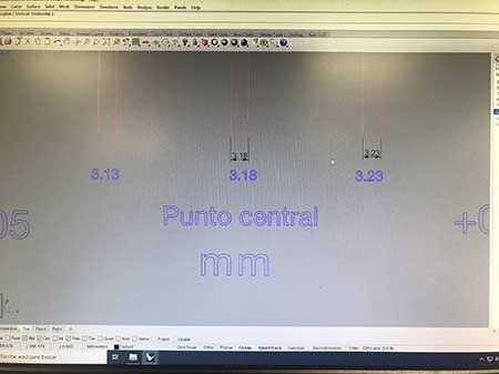
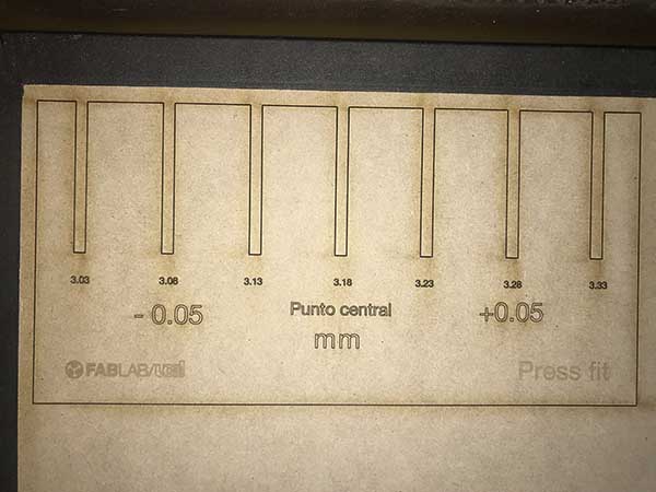
The final task was to work on a Pressfit We draw a rectangle with the width of the MDF table in the middle, which was 3.18mm. Then we write three numbers to the left and the same amount to the right. Each one with a tolerance of 0.05, substracting to the left and adding to the right.
WIDTHS WITH TOLERANCE (+0.05 / - 0.05)
| 3.03 | 3.08 | 3.13 | 3.18 | 3.23 | 3.28 | 3.33 |
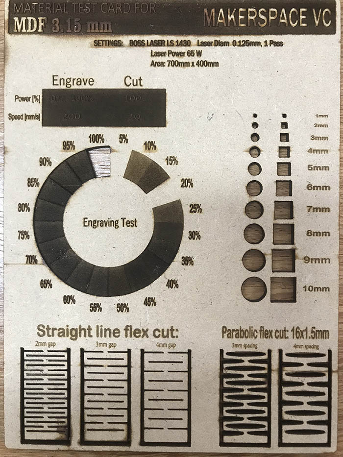
Engraving:
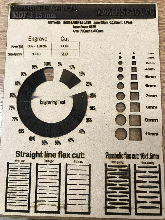
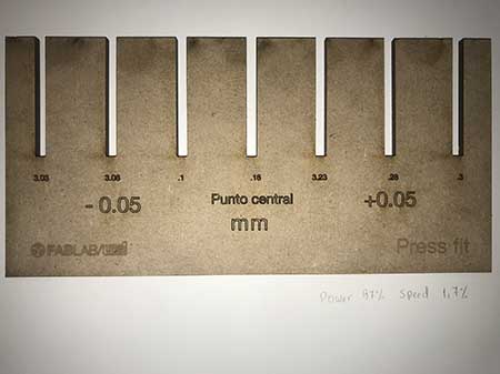
I design a Test Card to test how Boss Laser 1630 do its job with different percentages of engraving or scanning.
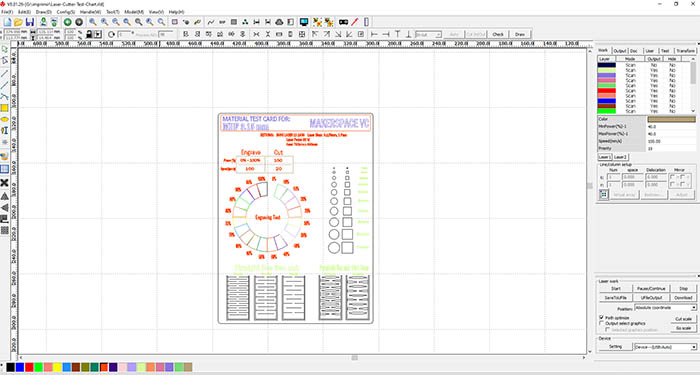
I start using the Boss Laser Cutter LS 1630 to engrave my work at different percentages and cut it finally.
Next the final product, the Test Chart.
Cutting in vinyl
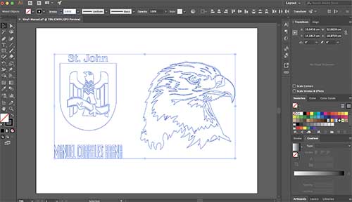
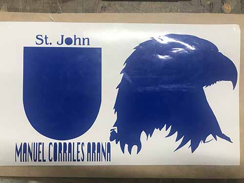
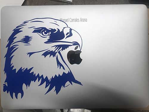
I use three images to print them in the vinyl cutter machine. I worked the images in Illustrator.
Here the file
LINK to Vinyl-File-Illustrator
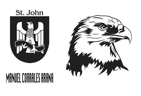
I vectorize all the drawing using illustrator.
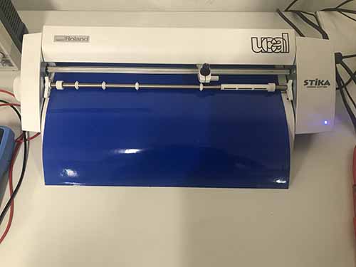
Then i configure the vinyl cutter and use the blue vinyl color to start this work.
But i realised that is nos as simple as it appears. This work failed for me. I start again.
We use the Vinyl cutter Roland SV15
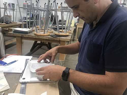
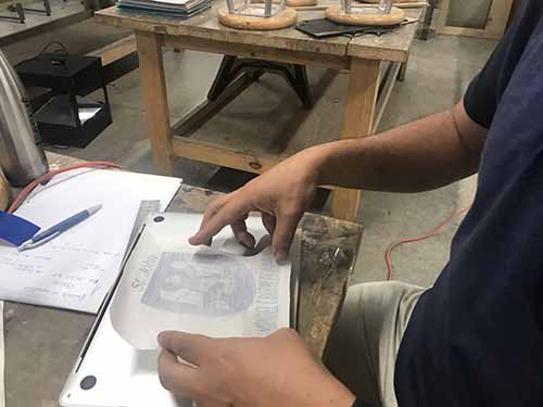
After the vinyl cutter cuted the vinyl i need to peel it carefully. A process that has to be done with a lot of patience.
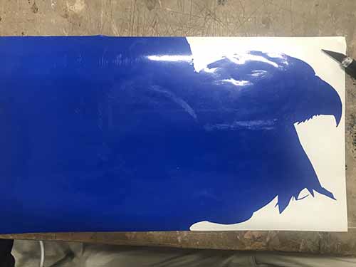
I have to take out the small layers that appears on the face of the eagle carefully. The idea is to take all the blue sheets that are not part of the image.
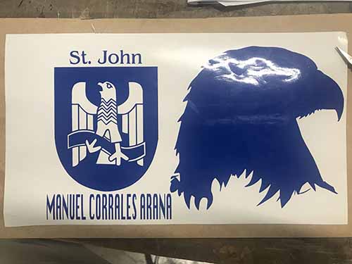
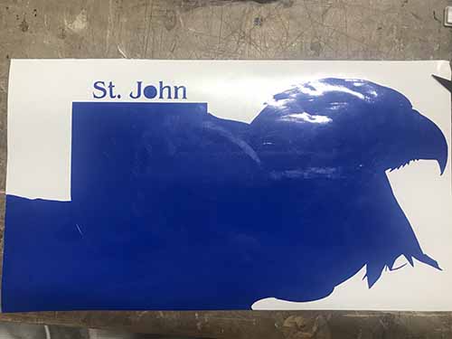
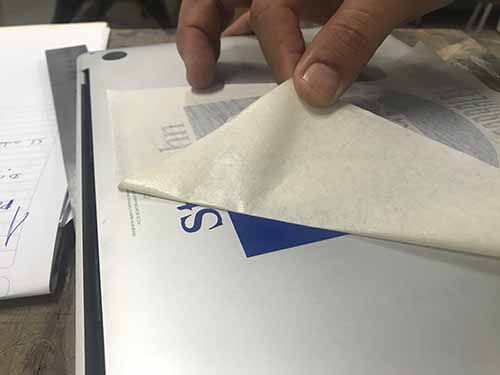
Finally i took out the blue sections that cover part of the head.

After i finished peeling off the sheets that aren´t part of the image, i have to stick a sticker sheet to pull away all the blue section that contain the image i want to stick over my Macbook Pro.
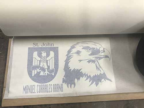
After i paste it carefully, i need to pull up carefully.
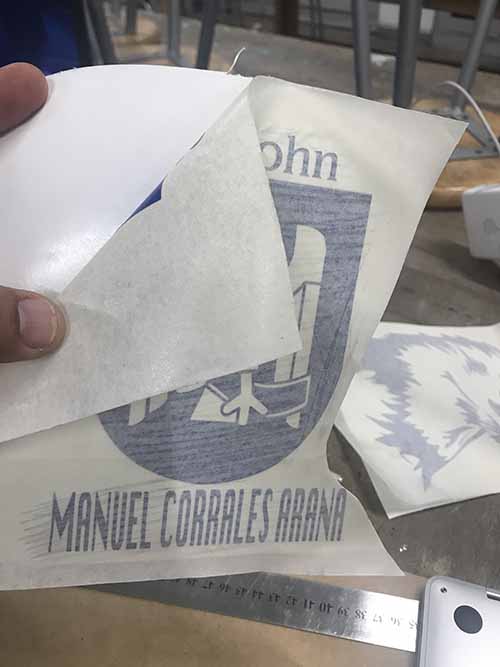
Then i locate the exactly position i want to stick my sticker and paste it.
Once i notice the the blue image is completely paste on my Macbook Pro, i pull the sticker sheet caefully.
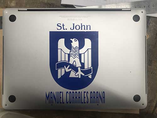
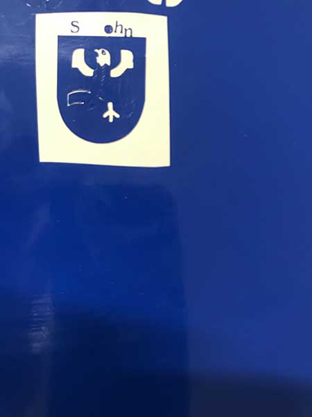
Finally, here the result. Awesome sticker.
Then i test the Laser cut.

After testing it works with another MDF of the same width.
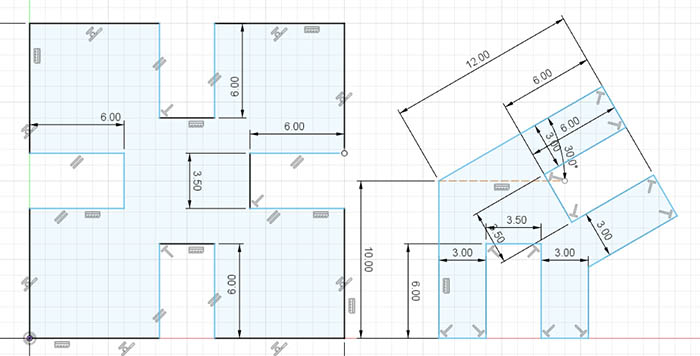
TASK 2: Personal assingment
Drawing fixable pieces
I draw some pieces using Fusion 360 and convert it to dxf for being used in Rhino before i use the Trotec laser.
Then i fit two figures and see the tolerance.
I test if the pieces cutted fit together tightly but it doesn’t because the tolerance is too high.
I used 3.23mm as a first measure of tolerance width of the MDF width is 3.18mm

So i change it to 3.18 and it fits somewhat tight and i adjust the tolerance substracting to 0.05 less, it means using a new measure of 3.13mm.
I did another Chart Test
In the video, some test done by moving it with my finger to notice how flexible are some of them.
Laser-Cutter-Test from Manuel Corrales Arana on Vimeo.
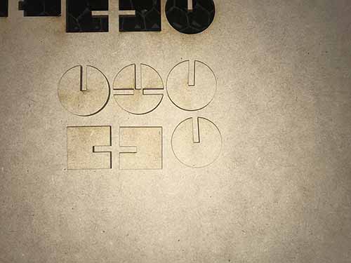
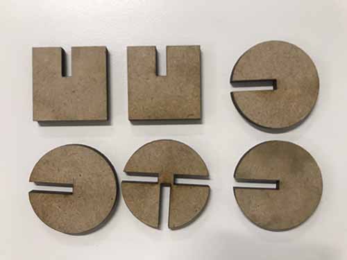
2nd Task: cut something on the vinylcutter> design, lasercut, and document a parametric construction kit,
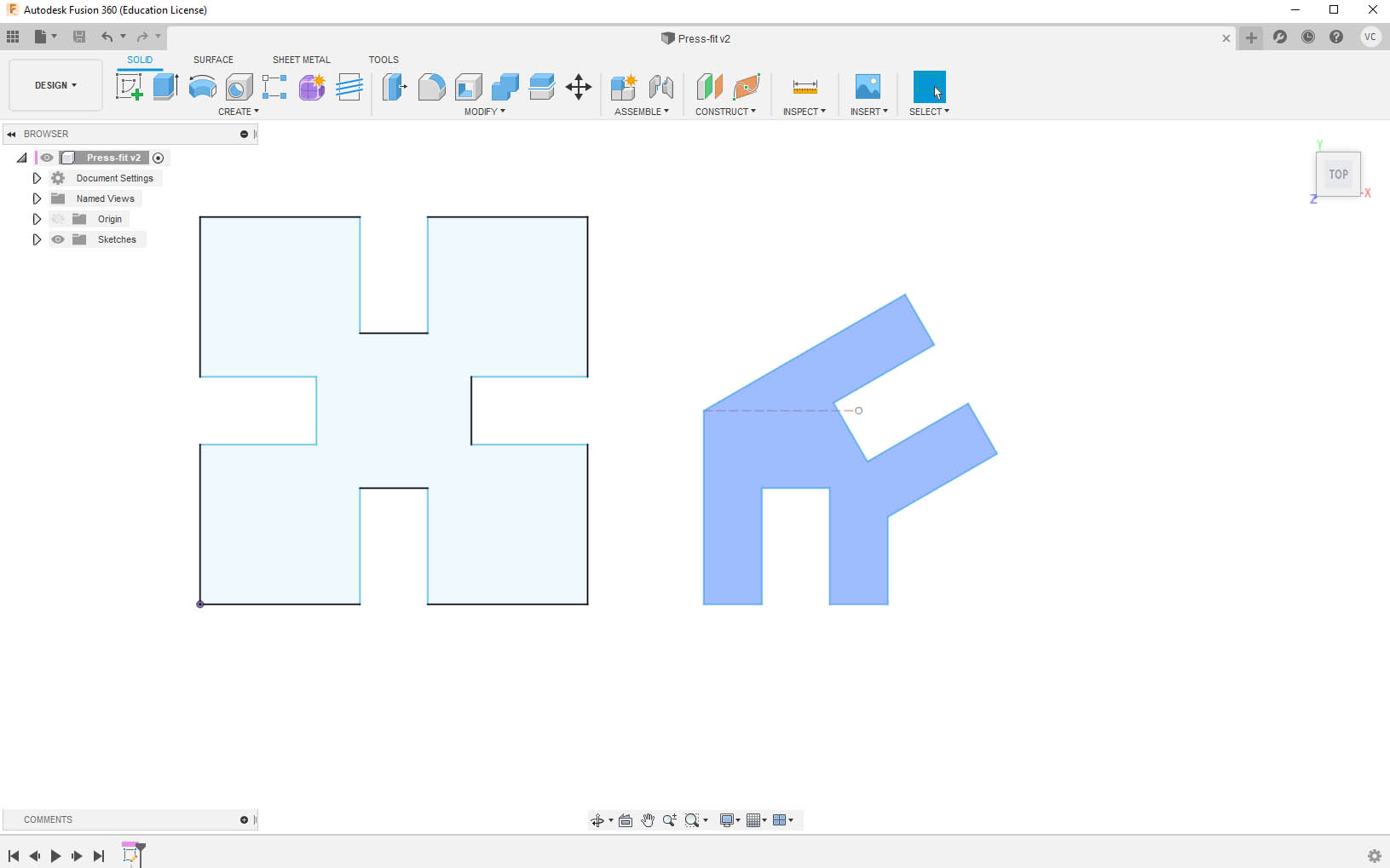
I use Fusion 360 to design a simple press-fit structure based on a square with four openings and four equal holders. I have ton consider the width of the material to be used, in this case MDF of 4mm and the respective tolerance.
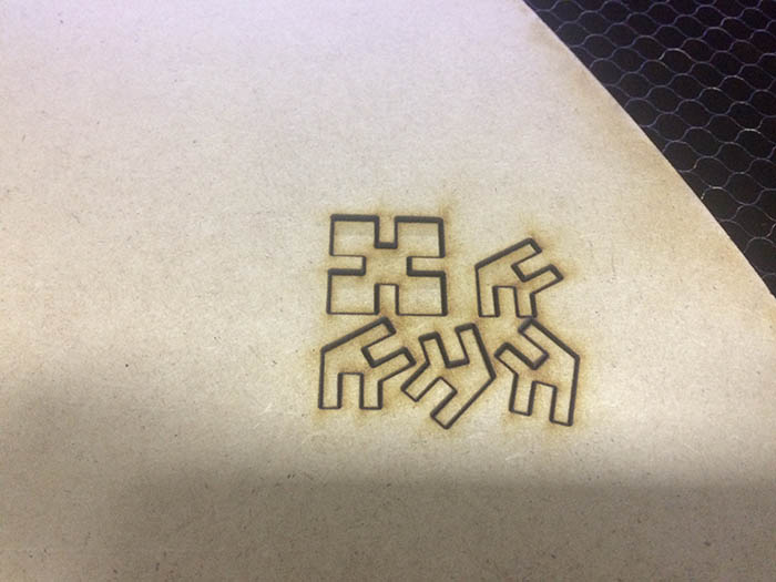
I use the Laser cut software to prepare the laser cutting process.
After laser cutting.

And finally plaing with this model which can be assembled in different ways.
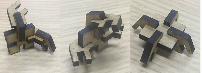
Laser-Cutter-PressFit model from Manuel Corrales Arana on Vimeo.
Here in this lesson, i learnt the whole process to make a vinyl sheet and it seems so simple but there are several steps to be considered. After the importance to calibrate some CNC machines like the laser cutter and the two important parameters to work with depending on the material to be used, meaning speed and power. Laser cut 85% power, 1% Speed for Trotec
Laser cut 85% power and 1% speed for Trotec Laser from Manuel Corrales Arana on Vimeo