11. Input devices
Individual Assignment
- Measure something: add a sensor to a microcontroller board
Step 1: –Using Tinkercad–
This week I worked on creating a circuit using tinkercad. I decide to use the temperature sensor and three leds. The LEDs will turn on in a specific range of temperature. Here the image of the circuit

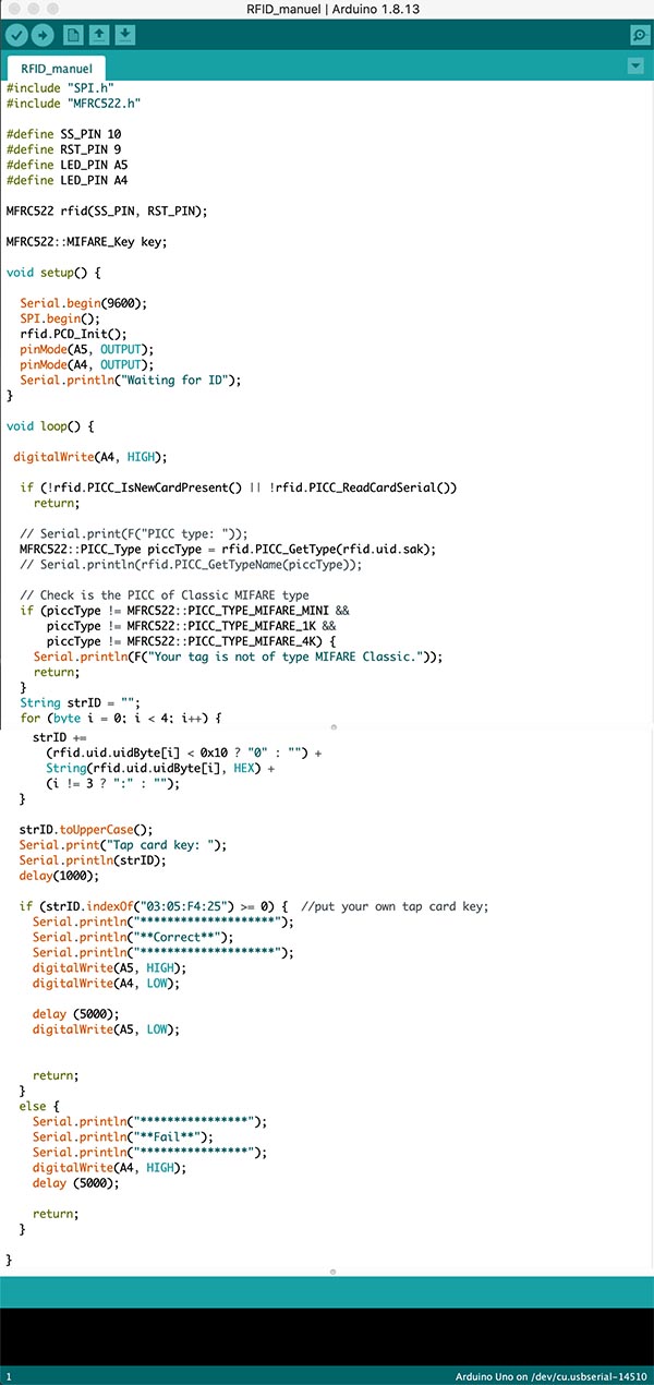
The code.

The results A. When the temperature is < 30 oC, the green led turns on.

B. When the temperatue is > 45 oC, the white led turns on.

C. When the temperature is greater than and equal to 30 oC and less and equal to 45 o C, the yellow led turns on.

Arduino wit LED and Temperature sensor from Manuel Corrales Arana on Vimeo.
Step 2: –Using Easyeda–
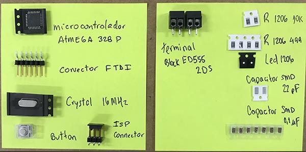
Using EasyEDA i pickup the following electronics:
__ELECTRONICS USED IN THE CIRCUIT__
| ITEM | ITEM | ITEM |
|---|---|---|
| ATTiny441-SSU | XTAL | LED SMD 1206 RED |
| RESISTORS 1206 1K | FTDI UART | VCC |
| 1 Beefy 3 FTD | GND | TEMPERATURE SENSOR |
| LEDS SMD 1206 BLUE | LED SMD 1206R YELLOW |


Files
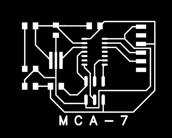
Circuit board - PCB Cirbuit board - Border
Finally i worked all about this assignment in my project due to the pandemic, because the government closed all educations institutions. I worked in the Makerspace in my school.
DESIGN OF THE PCB FOR MY PROJECT
Finally i worked all about this assignment in my project due to the pandemic, because the government closed all educations institutions. I worked in the Makerspace in my school. Here what i worked as part of my Project.
DESIGNING THE ELECTRONICS
I print the schematics to check it that everything is ok, then i go with the PCB.
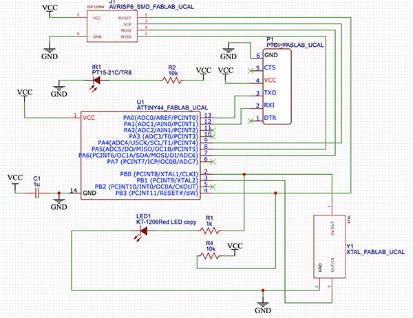
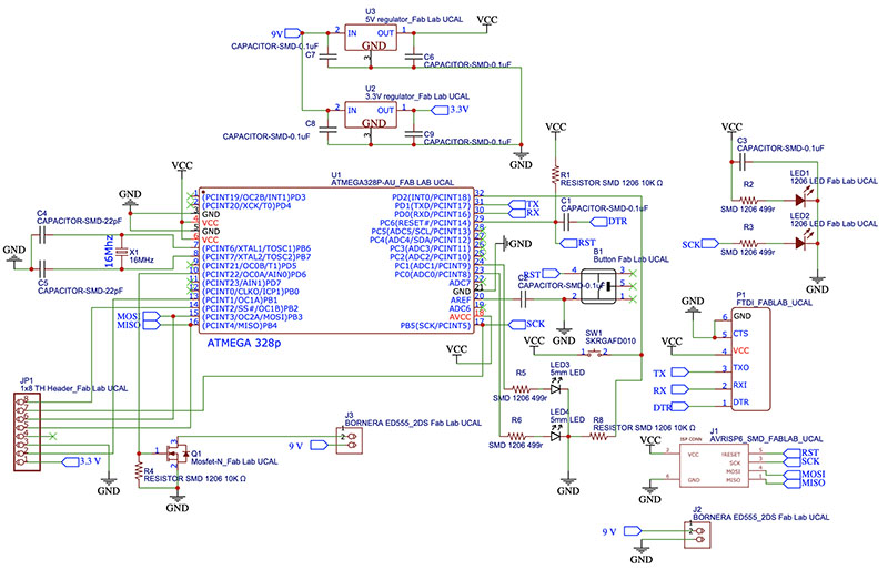
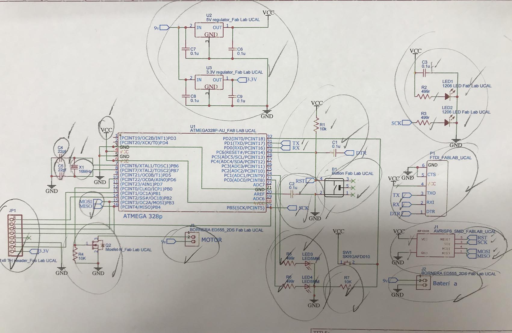 Schematics done in Easyeda online free software
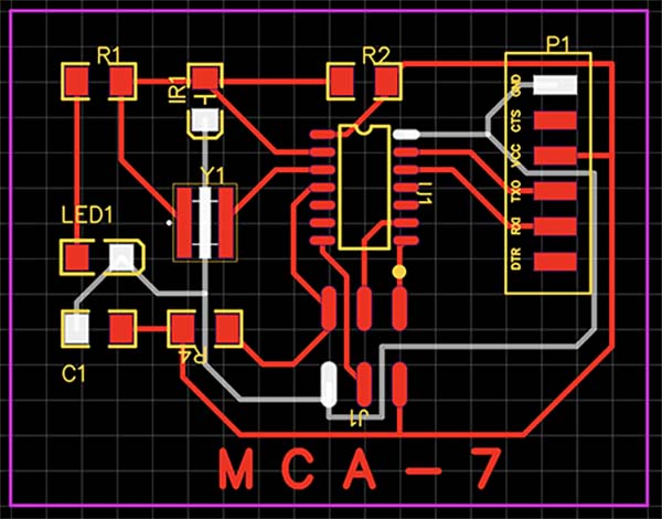
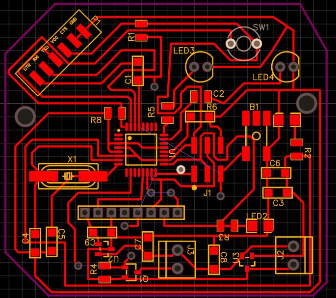
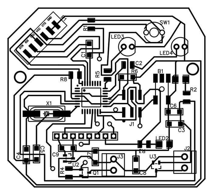
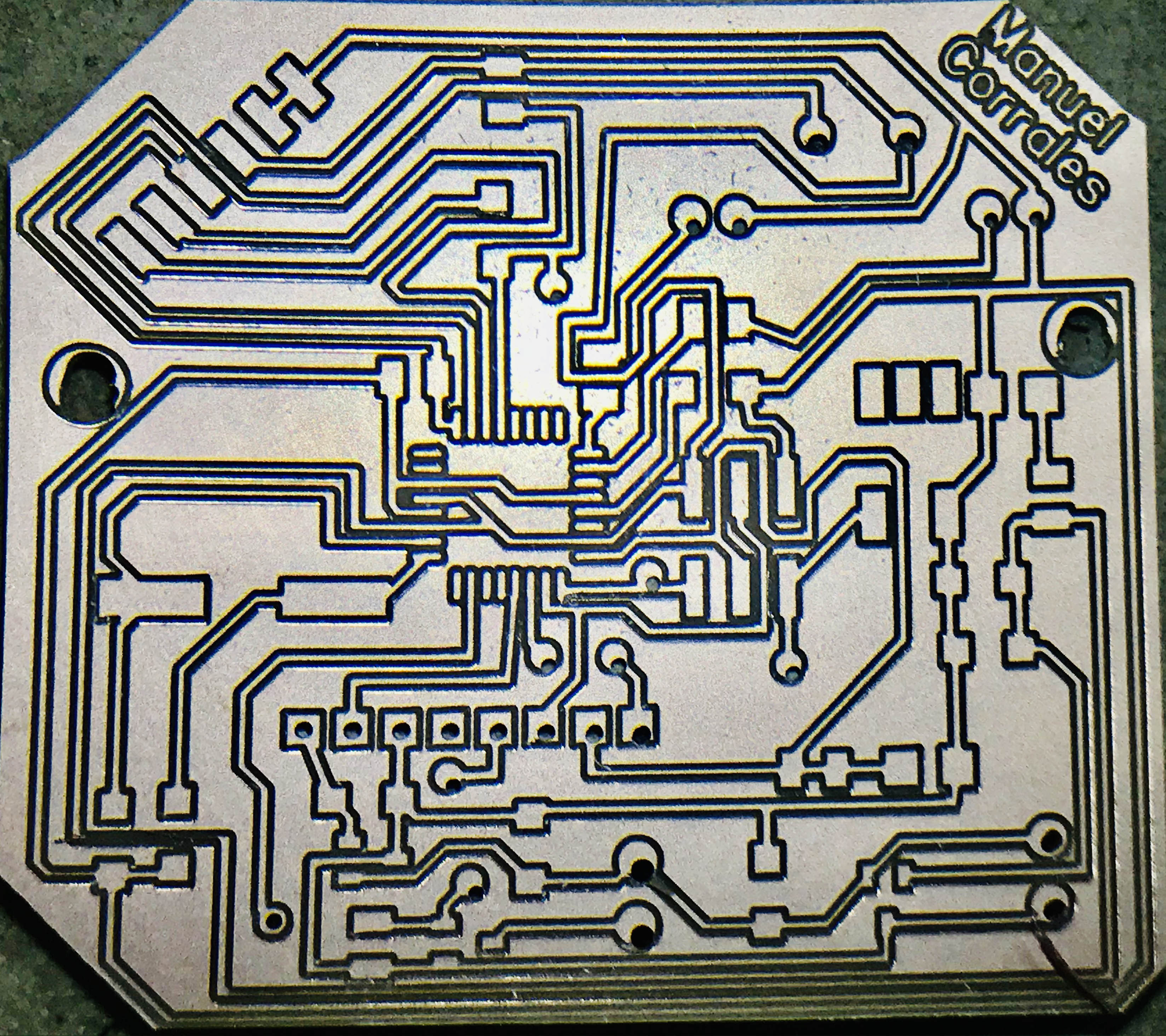
PCB done in Easyeda
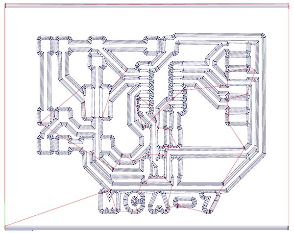
The Gerber view
The Gerber format is an open 2D binary vector image file format. It is the standard file used by printed circuit board or PCB industry software to describe the printed circuit board layers: copper layers, solder mask, legend

I make some corrections to the PCB because some traces were to close and i have to condiser that the RFID has to be a little far away from the LEDs connections. I draw the lines that measures the position of the LEDs and that of the holes.
Now the processing of my PCB done in EasyEda by Flatcam First Open Flatcam and in the options section, i select the units in mm. Then i open the Gerber file that contains the information about the Traces. Open Gerber We have to add the configuration of the Milling machine as follows for the traces. Endmill of 1/64
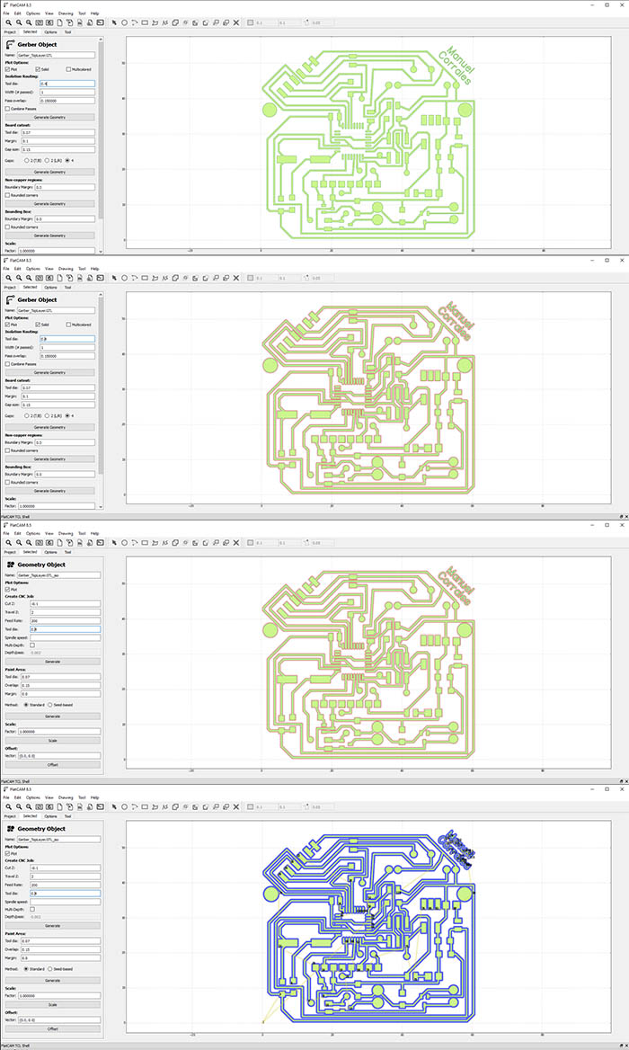
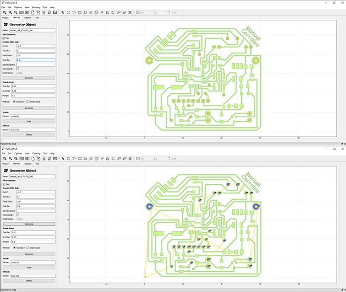
on of the traces, i continue with that of the holes. Endmil of 1/32
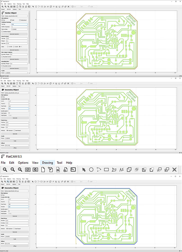
Finally the configuraion of the border. Same endmill as holes.
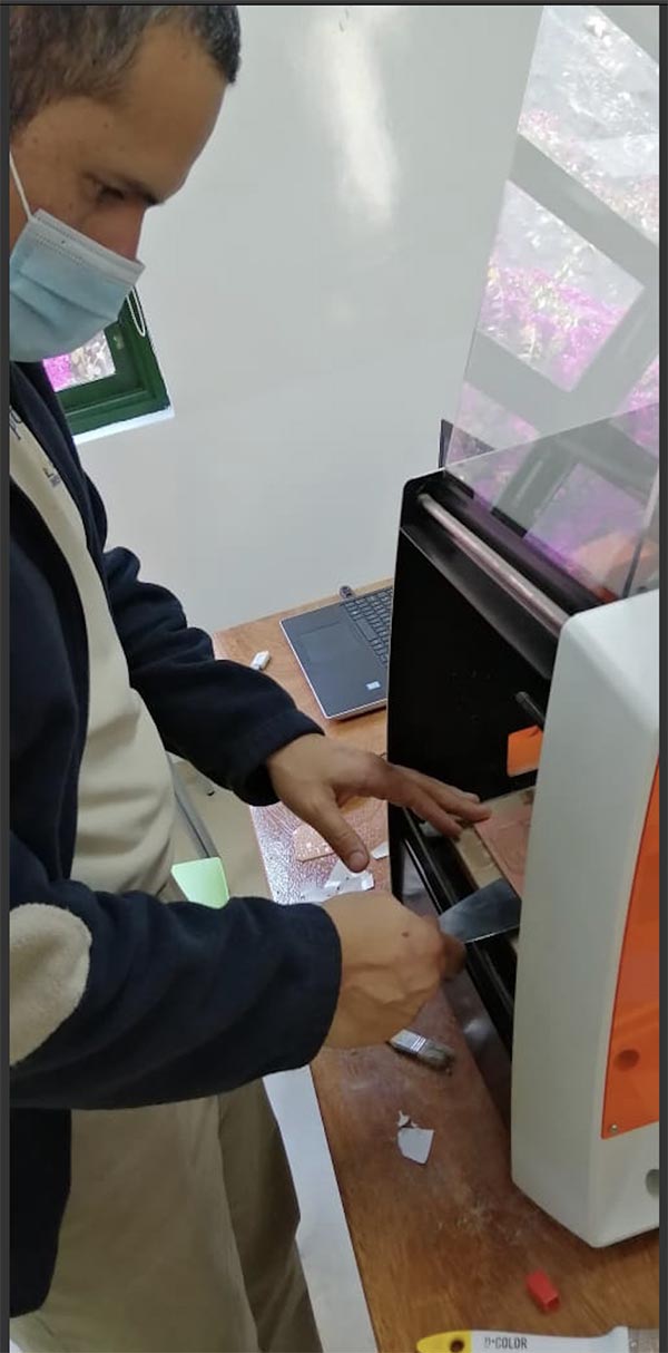
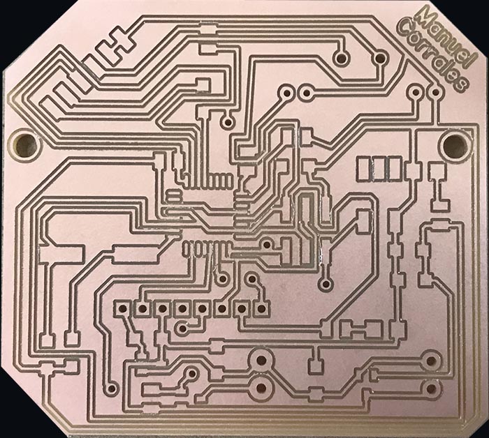
After having all the archives for drilling the PCB i use the Milling machine to make my PCB
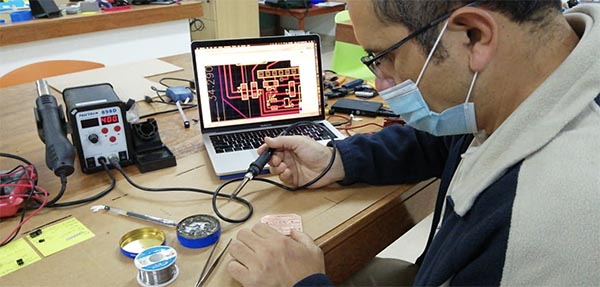
I started the next step: Soldering all the micro components. First place all the electronics in my table, the soldering station, and safety equipment.
This is the new PCB done where i improve some conections didn´t done.
Then i start soldering all the components.

I am going to test the button as an input.
Testing the motor with the button.
Testing the motor from Manuel Corrales Arana on Vimeo.
It works.
Now i tested the RFID Card i am going to use for my Project.
TESTING THE RFID CARD WITH ITS READER IN ARDUINO The red light turns off and the green one on when the Card passes through it.
Testing the Arduino with RFID Reader and Card from Manuel Corrales Arana on Vimeo.
Testing the RFID Card from Manuel Corrales Arana on Vimeo.
Group Assignment
- Group assignment: Probe an input device’s analog levels and digital signals.
I use a led as output to find the reading voltage per time in an oscilloscope. Notice the simple code in Arduino.

I use a delay of 30 ms for turning on with a delay of 50 ms to turn off the led. After for comparison i change the delay in both cases for the same amount, 50 ms. It is quiete impossible to notice by our eyes but the oscilloscope detect it. Notice that the line below is larger than that at the top.
Reading the voltage value over time with an oscilloscope from Manuel Corrales Arana on Vimeo.
With this lesson i learnt how to use electronic components, solder them, build a PCB and programming it. Amazing task and completely new for me. The use of the oscilloscope is completely new for me and quiet interesting to notice how voltabe can be seen as lines.