5. Electronics production
This week I worked on making my circuit board using a milling machine. Preparing the Circuit Template
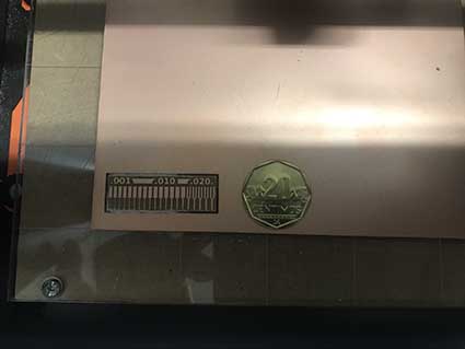
TASK 1: Characterizing the design rules for PCB Production
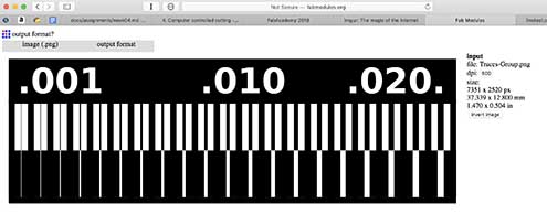
- Step 1: Save the image from CAM traces store in the web.

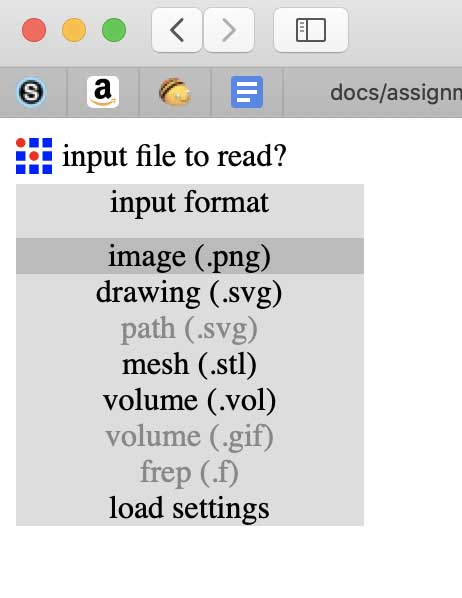
- Step 2: Open Fabmodules
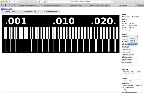
- Step 3: Use the input file to read and open the image in the image (.png) section.
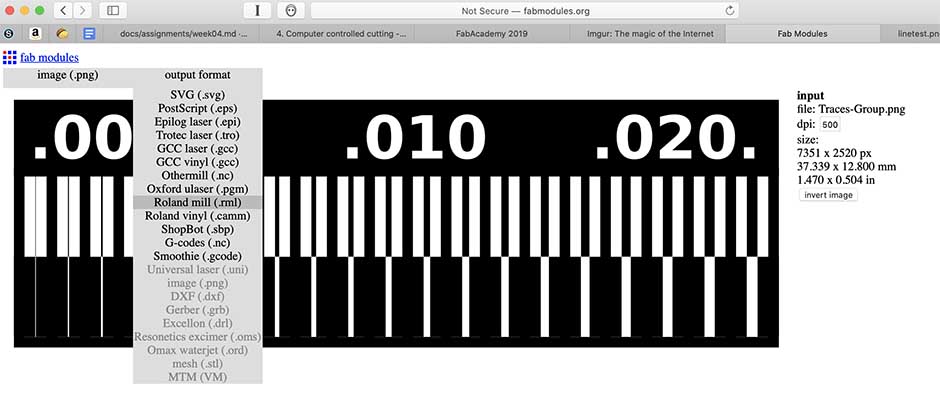
- Step 4: Once the image is opened then we use the Roland Mill in the output format.
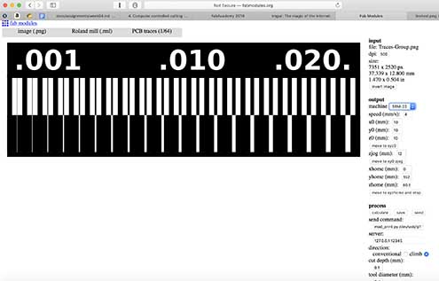
- Step 5: Choose PCB traces (1/64), which is the measure of the endmill
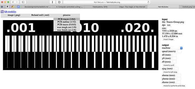
- Step 6: Choose the model of the milling machine which is SRM 20
- Step 7: Use the following parameters, especially the too diameter to 0.4mm and the number of offsets to 4
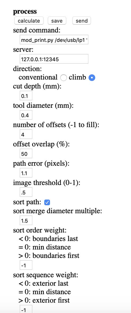
- Step 8: Then we have to “calculate” the traces with all the information added.
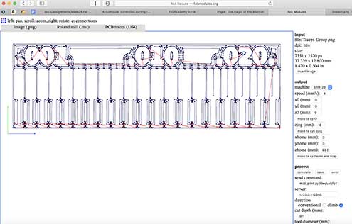
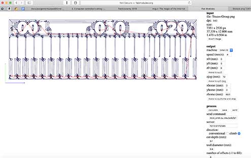
- After all the information added, we save our image and then we are going to open the software of the milling machine to start running the printing of our circuit board and cut it.
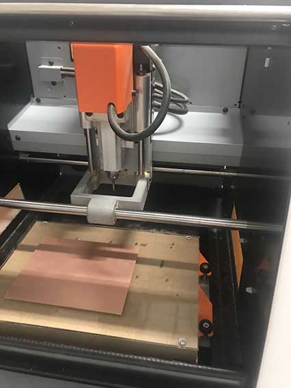
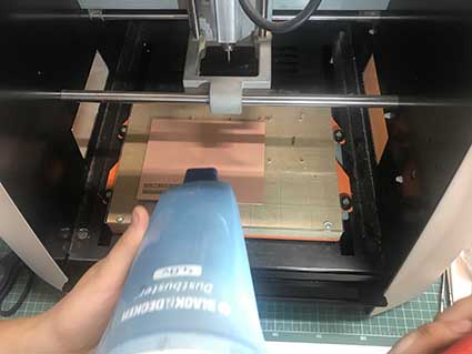
Preparing the Milling
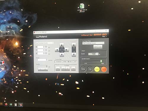
- The Milling machine is a Roland SRM 20
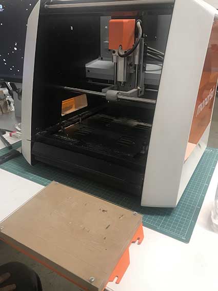
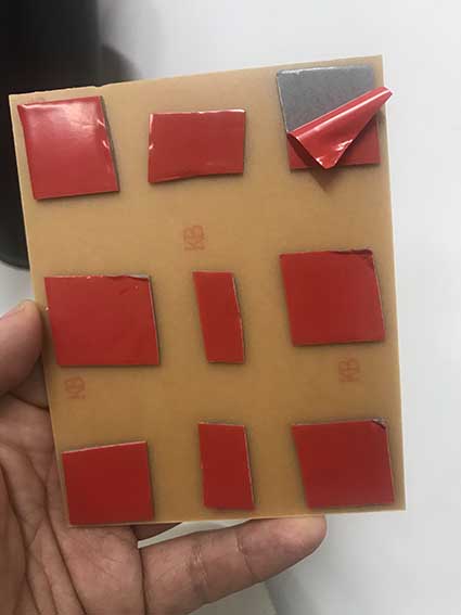
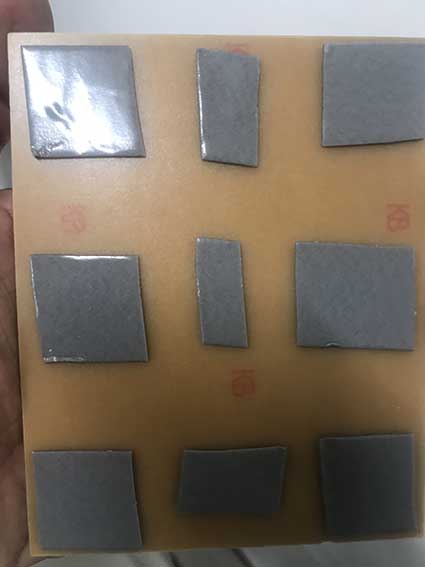
- Then we attached double contact tape to the FR1 Board to attach it to the base. This FR1 PCB Board is a hard material that conists of a thin layer of Cu over a non conductive resin, usually cellulose.
-
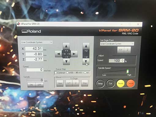
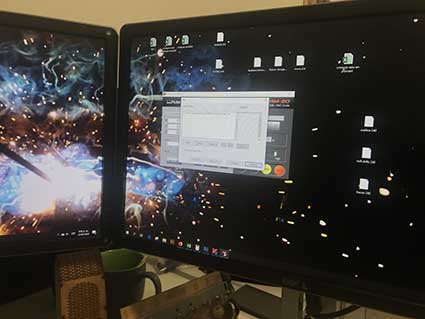
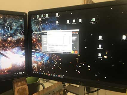
We open the software for the Roland Milling machine.
-
Then we put the corresponding end mill 1/64 for trafes, and tighten it.
- Here a picture of two end mills with a microscope view.
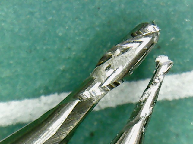
[Adding endmills for a Roland Milling Machine]
- And start the calibration process in the three axis, X, Y and Z.
- Once the milling machine is calibrated, we set to cut.
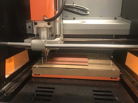
[Cutting in the Roland Milling Machine]
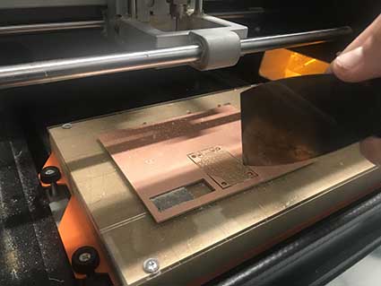
- After, we have to clean the board removing the dust or chips.
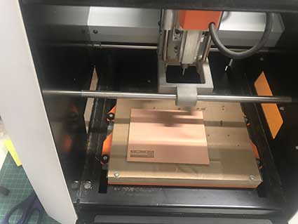
- The second part of the procdss is to make the holes and cut the board.
[Cutting in the Roland Milling Machine]
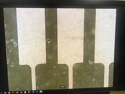
- Was incredible the precission of the milling machine and we do have a microscope to look it deeper and how it is.
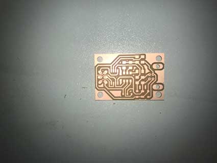
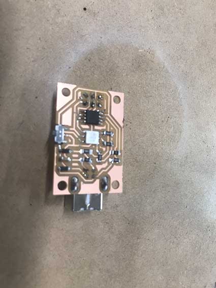
Here my first microcontroler PCB work. It has a LED that tells whether the information is being loaded (red blinking), programming communication (purple blinking)
TASK 2: Making a circuit programmer by milling, stuffing the PCB and soldering. Test it.
What is the FabISP?
The FabISP is an system programmer for AVR microcontrollers, designed for production within a FabLab. It allows to program the microcontrollers on other boards you make.
Here the model of the circuit that is being milled using the same procedure done before.
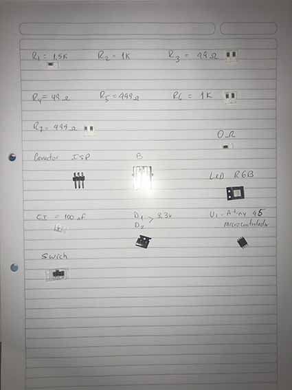
Here the electronic components i need.
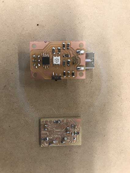
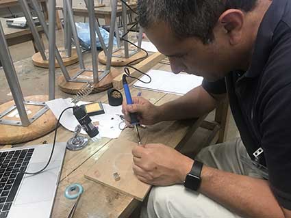
But before i practice soldering and stuffing in a small milled pcb.
One problem i had was that my presbyopia didn’t let me work well, so i use a microscope to be use that the stuffing is well done.
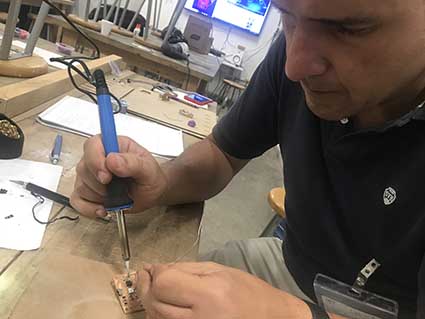
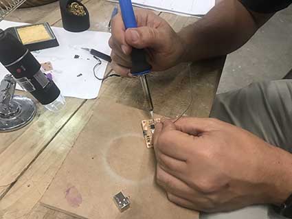
Finally, y end the process after 2.5 hours of work but i enjoy it. Requires lot of patience and concentration.
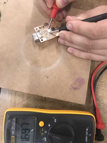
Finally, i test if it conducts electricity and it does.
For programming on my Mac i follow the instructions on the Tutorial ]FabISP - Programming](http://archive.fabacademy.org/archives/2017/doc/programming_FabISP.html#mac)
Then i have to download the CrossPack for AVR Development CrossPack
Download the latest firmware FabISP Firmware for MacOS
In Terminal, write
“cd ~/Desktop/” Then unzip the firmware.zip directory unzip fabISP_mac.0.8.2_firmware.zip
After, move to the newly created firmware directory in your desktop cd ~/Desktop/firmware
Edit the Makefile by Openning the Makefile with TextEdit.
Go to the line that says:
AVRDUDE = avrdude -c usbtiny -p $(DEVICE) # edit this line for your programmer
AVRDUDE = avrdude -c avrisp2 -P usb -p $(DEVICE) # edit this line for your programmer
- If using the USBtiny programmer or another FabISP
- Remove the “#” in front of the line with “usbtiny” in it
- Add a “#” to beginning the line with the “avrisp2” in it to comment it out.
- save the Makefile
For Programming: cd Desktop/fabISP_mac.0.8.2_firmware Type: Make clean (This to compile the firmware)
The system will response by the following:
| akaziuna@Titan:~/Desktop/firmware$ make clean rm -f main.hex main.lst main.obj main.cof main.list main.map main.eep.hex main.elf .o usbdrv/.o main.s usbdrv/oddebug.s usbdrv/usbdrv.s |
Then, type: make hex
The system will response with the following:
|akaziuna@Titan:~/Desktop/firmware$ make hex avr-gcc -Wall -Os -DF_CPU=20000000 -Iusbdrv -I. -DDEBUG_LEVEL=0 -mmcu=attiny44 -c usbdrv/usbdrv.c -o usbdrv/usbdrv.o avr-gcc -Wall -Os -DF_CPU=20000000 -Iusbdrv -I. -DDEBUG_LEVEL=0 -mmcu=attiny44 -x assembler-with-cpp -c usbdrv/usbdrvasm.S -o usbdrv/usbdrvasm.o avr-gcc -Wall -Os -DF_CPU=20000000 -Iusbdrv -I. -DDEBUG_LEVEL=0 -mmcu=attiny44 -c usbdrv/oddebug.c -o usbdrv/oddebug.o avr-gcc -Wall -Os -DF_CPU=20000000 -Iusbdrv -I. -DDEBUG_LEVEL=0 -mmcu=attiny44 -c main.c -o main.o avr-gcc -Wall -Os -DF_CPU=20000000 -Iusbdrv -I. -DDEBUG_LEVEL=0 -mmcu=attiny44 -o main.elf usbdrv/usbdrv.o usbdrv/usbdrvasm.o usbdrv/oddebug.o main.o rm -f main.hex main.eep.hex avr-objcopy -j .text -j .data -O ihex main.elf main.hex avr-size main.hex text data bss dec hex filename 0 2020 0 2020 7e4 main.hex |
Type: Make fuse (this is to set the fuses)
Is everything is ok, finally you will succedd.
|**akaziuna@Titan:~/Desktop/firmware$ sudo make fuse avrdude -c usbtiny -p attiny44 -U hfuse:w:0xDF:m -U lfuse:w:0xFF:m
avrdude: AVR device initialized and ready to accept instructions
Reading | ################################################## | 100% 0.01s
avrdude: Device signature = 0x1e9207 avrdude: reading input file “0xDF” avrdude: writing hfuse (1 bytes):
Writing | ################################################## | 100% 0.00s
avrdude: 1 bytes of hfuse written avrdude: verifying hfuse memory against 0xDF: avrdude: load data hfuse data from input file 0xDF: avrdude: input file 0xDF contains 1 bytes avrdude: reading on-chip hfuse data:
Reading | ################################################## | 100% 0.00s
avrdude: verifying … avrdude: 1 bytes of hfuse verified avrdude: reading input file “0xFF” avrdude: writing lfuse (1 bytes):
Writing | ################################################## | 100% 0.01s
avrdude: 1 bytes of lfuse written avrdude: verifying lfuse memory against 0xFF: avrdude: load data lfuse data from input file 0xFF: avrdude: input file 0xFF contains 1 bytes avrdude: reading on-chip lfuse data:
Reading | ################################################## | 100% 0.00s
avrdude: verifying … avrdude: 1 bytes of lfuse verified
avrdude: safemode: Fuses OK
avrdude done. Thank you.**|
This task was difficult to me because is the first time for doing electronics and programming. New issues i acquire and seems great when everything works.