Final Project
My final projects is related with education.
Introduction
One of the important issues i observed is to implement a new way to teach science by using some tools where technology is involved. We usually buy different equipment or material in the vast market for those items. Now i am relating a robot previously used for some classes and involve it with a subject like science.
Previous background
I based my project in a Beebot robot which is commonly used to introduce programming by moving in diferent directions. I use this model in combination with a science related topic.
Objective
Using the “Animal-Bot” the student will learn in a fast way that each animal lives in a specific habitat.
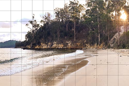
This is an image of a random habitat.
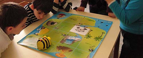
The way to do this is like a contest where one student will say several characteristics of a specific habitat and the other student will guess the answer by letting the robot move to the habitat being described.
What does it do?
- The robot will move several blocks and the green light will turn on where the RFID card is located meaning that the drawing is the correct answer. First i have to put it below according to the answer of the question planned.
Who’s done what beforehand? - Nobody as what i think.
What did you design? - I design the model of the robot, the electronics, the program, the laser cut MDF block.
What materials and components were used? - MDF, PLA for the 3D printing case, electronic components including the RFID Card, Acrylic.
Where did they come from? - Materials come from the UCAL´s FabLab and a few from the Makerspace VC.
How much did they cost? - Aproxiamate $300 due to the several trials and errors.
What parts and systems were made? - The robot case, the PCB with all the soldered electronic components, the blocks made of MDF.
What processes were used? - Laser cutting, Milling, programming, electronic design, soldering, debugging.
What questions were answered? - How can i integrate the RFID card sensor with the motor gear in the programming ? - Does the electronics fit in the case? Which i have to work before, the case or the PDB?
What worked? What didn’t? - Everything worked due to the different trials. At the beginning i have spend a lot to time with the button by debouncing it.
How was it evaluated? - By pressing the button the times where i want to move depending on where the RFID Card is, so it the green light turns on, it works.
What are the implications? - This work will be used in science class as a short game and is intended for other people to use it in education.
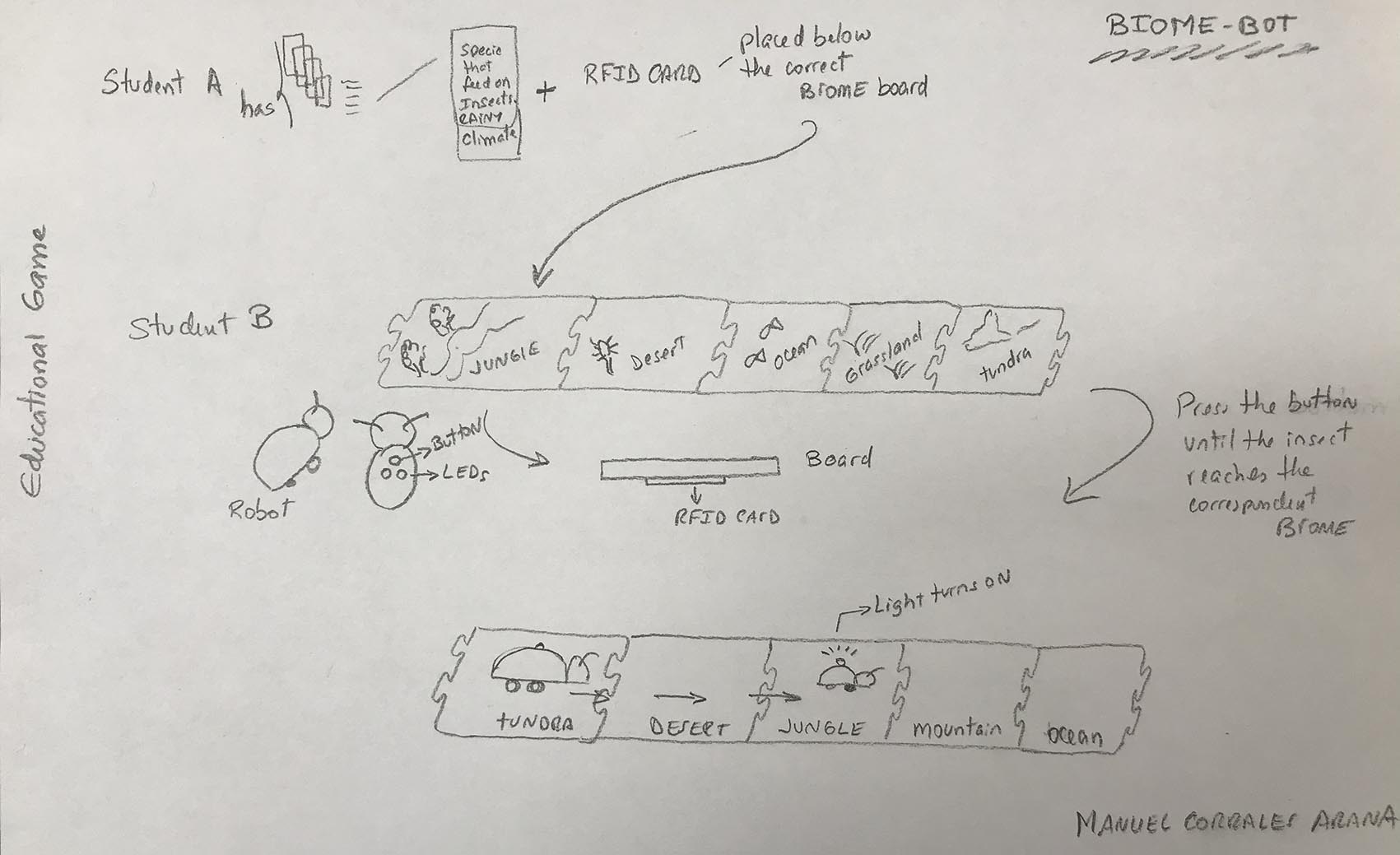
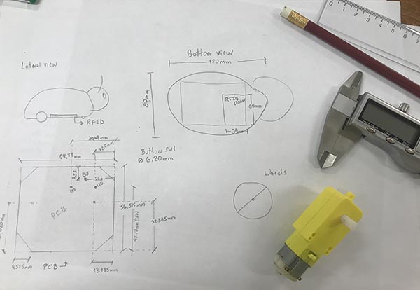
SKETCH :
a. Board.
After delivering different issues of my project i redo it and is as follows.
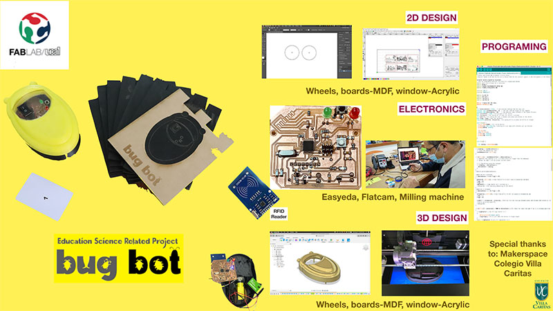
EDUCATIONAL ECOSYSTEM GAME
PARTS TO BE DESIGN FOR MY PROJECT
| STRUCTURE | SOFTWARE (CAM) | CAD |
|---|---|---|
| BASE Design | Using Illustrator | Laser cutter |
| 3D ROBOT STRUCTURE | FUSION 360 | 3D PRINTER |
| ELECTRONICS | Easyeda/FlatCam | Roland Milling machine |
| CODE | ARDUINO + RFID Reader and Card | – |
DESIGNING THE BASE
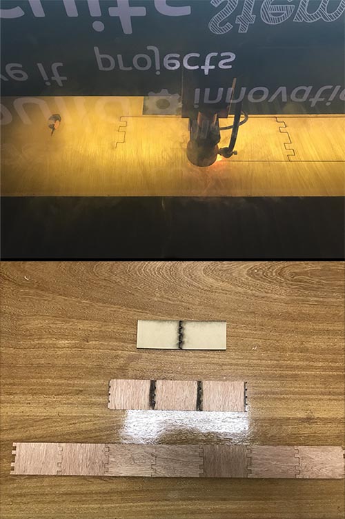
I use illustrator to build the base where the animal robot will move. I try first using 5mm MDF but it was a little messy in the boarders and i need to pass twice throught the Laser Cutter machice to cut it. Seems a little burned.
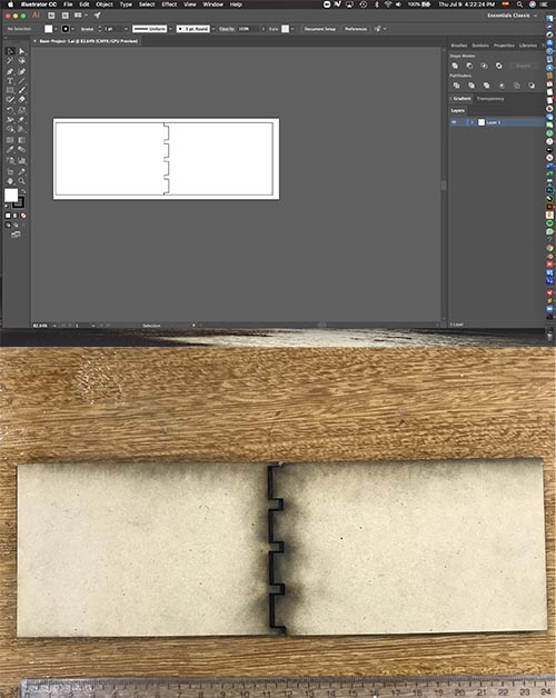
We try different materials and finally due to the strengh and the most easiest to cut i use 4mm plywood build like a puzzle.
3D Printing Insect Model from Manuel Corrales Arana on Vimeo.
The final puzzle with all the pieces of the different Biomes.
| DIMENSION | Measures | # of Boards |
|---|---|---|
| Length | 210 mm | 06 |
| Width | 148 mm |
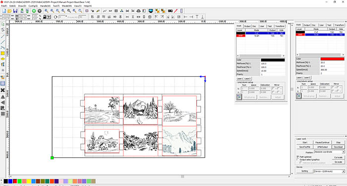
Then i CUT in the Boss Laser LS1630
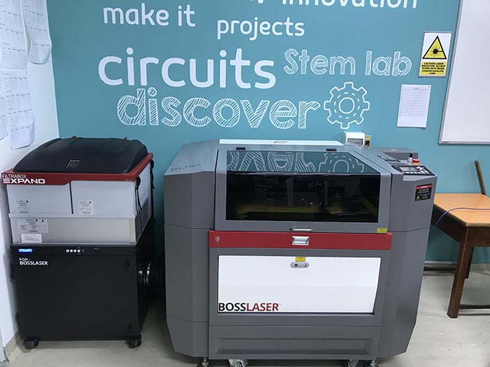
usint the following parameters from the RDWorksv8 Software
| OBJECT | SCAN POWER% | SCAN SPEED |
|---|---|---|
| MDF 3mm | 30 % | 100mm/s |
| :-------------: | :-----------------: | :---------------: |
| OBJECT | CUT POWER% | CUT SPEED |
| MDF 3mm | 100 % | 20mm/s |
The length of the 06 pieces of biomes, ready to play. Here the 06 MDF Cards for the base. Each one contains an image of a specific biome or natural area that has to be identify according to the questions given. The girl has to move the animal bot to the correspondent natural area.
Natural Areas - Biomes MDF Card from Manuel Corrales Arana on Vimeo.
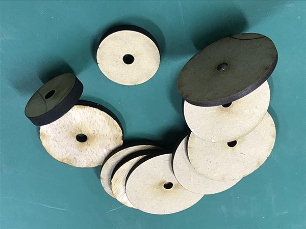
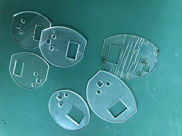
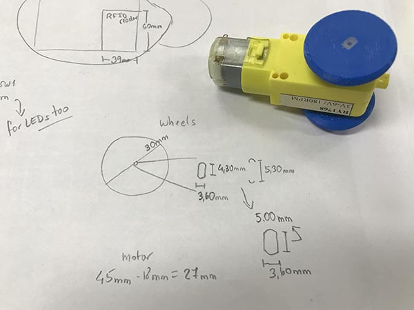
A second part that has to do with 2D design are the wheels and the window of the bug in acrylic.
First two wheels with a diameter of 35mm and the circle inside of 5mm to be attached in the motor made in 5mm MDF.
Then the window made up in a 3mm acrylic piece of sheet. The sketch was taken from the sketch done in Fusion 360.
DESIGNING THE ELECTRONICS
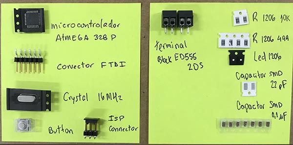
c. Electric/Electronic components and measurements. Some important electronic components that do take volume to be consider in the design of the robot.
| ITEM | Measures | Quantities | Total Cost($) |
|---|---|---|---|
| PCB | 01 | 27 | |
| BATTERY 9V | 60mm x 27mm x 16mm | 02 | 6 |
| Gear motor wheel | 63.5mm x 22mm x 18mm thick | 01 | 3.5 |
| Atmega328 P-AU | 01 | 2 | |
| X1 16MHZ | 01 | 0.70 | |
| Capacitor SMD 0.1uF | 07 | 0.7 | |
| Capacitor SMD 22pF | 02 | 0.2 | |
| RFID Interface | 01 | 4 | |
| AVR ISP 6 pinS | 01 | 0.50 | |
| FTDI | 01 | 0.6 | |
| Terminal block ED555 2DS | 02 | 3.12 | |
| Switch tactile button SKRGAFD010 | 01 | 0.40 | |
| lED 5mm | 02 | 0.50 | |
| Resistor 1206 10K | 03 | 0.3 | |
| Resistor 1206 499r | 04 | 0.4 | |
| PIN Header 1206 499r | 04 | 0.8 | |
| MOSFET-N-CH 30V 1.7A | 01 | 0.30 | |
| BUTTON | 01 | 0.6 | |
| 3.3V REGULATOR | 01 | 0.5 | |
| 5V REGULATOR | 01 | 0.5 | |
| LED 1206 | 02 | 0.2 |
I printed the schematics to check it that everything is ok, then i go with the PCB.
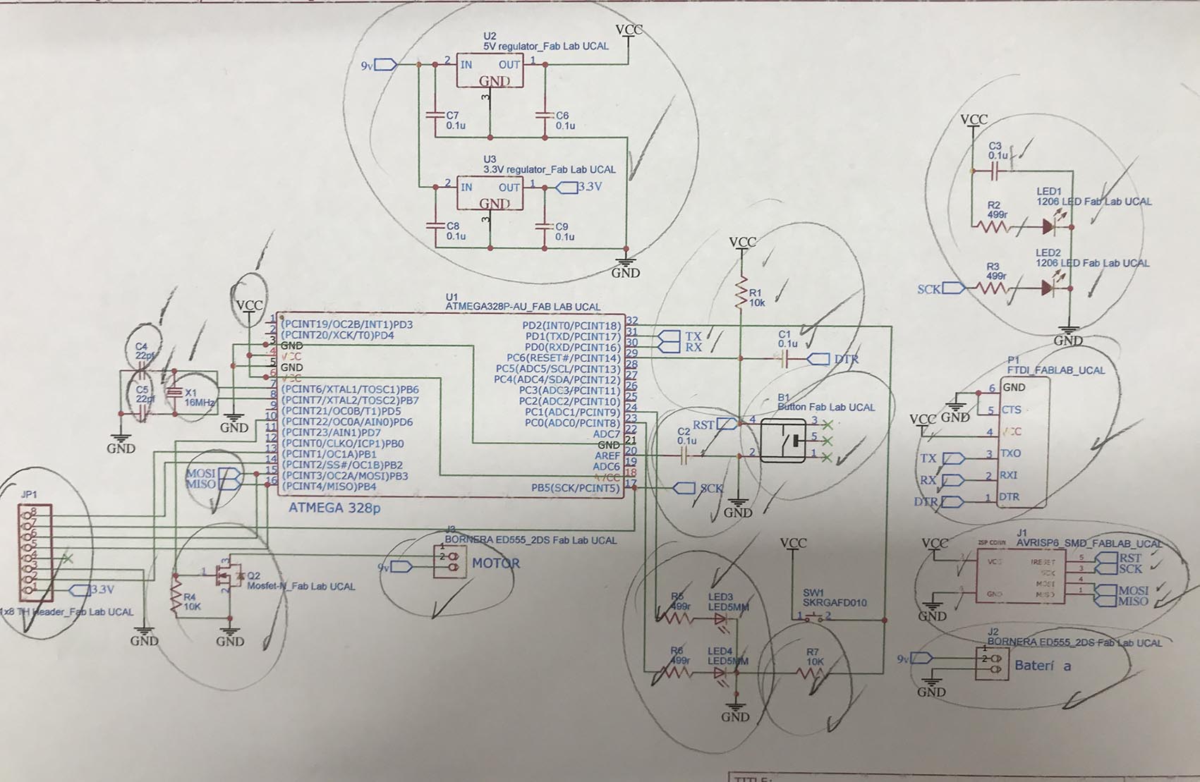 Schematics done in Easyeda online free software
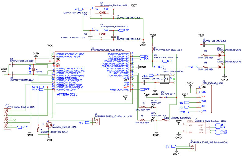
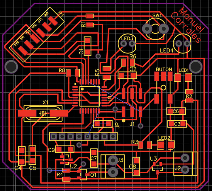
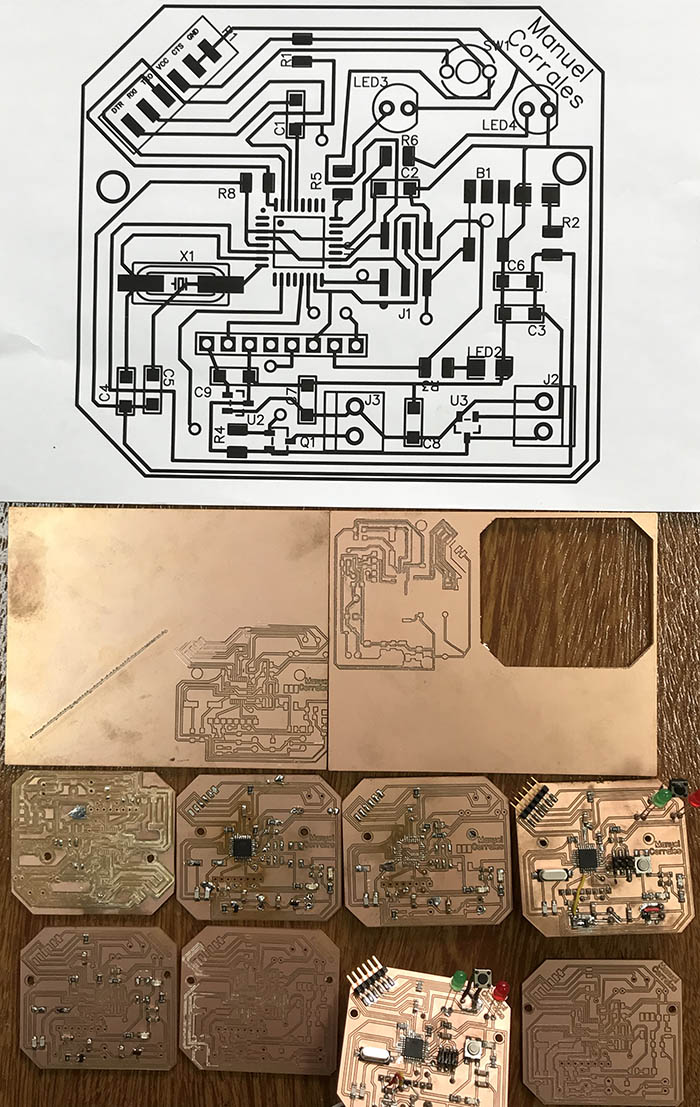
PCB done in Easyeda
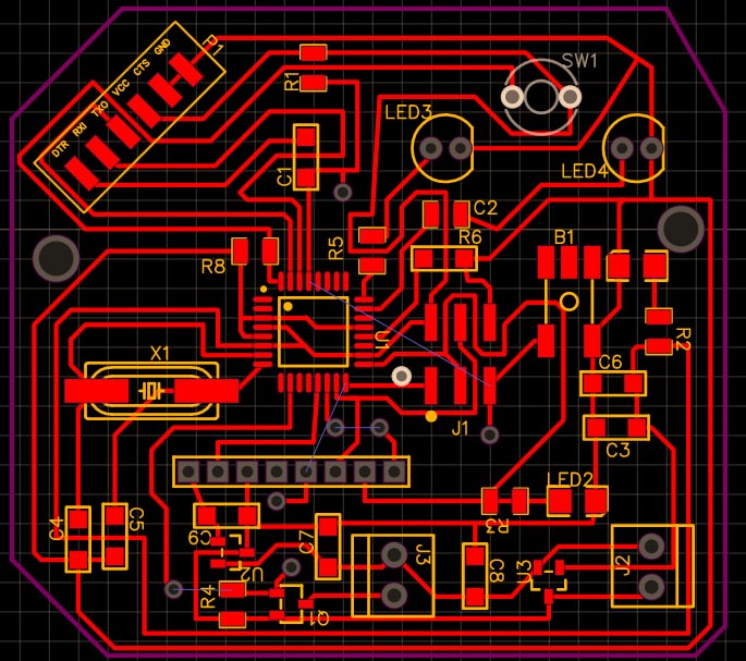
PCB done with all the corrections due to some mistakes: - Two wide holes for the terminal blocks, so they are nof tightly fixed. - Better arrangement due to the exact location of the RFID Reader making it do not interfere with other visible components.
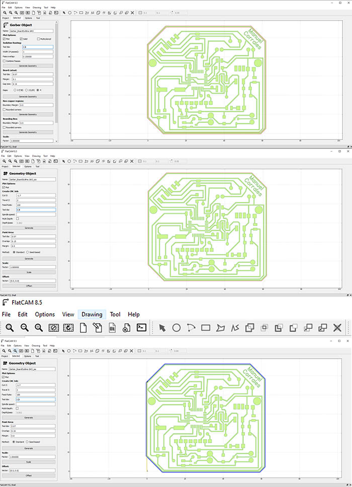
The Gerber view
The Gerber format is an open 2D binary vector image file format. It is the standard file used by printed circuit board or PCB industry software to describe the printed circuit board layers: copper layers, solder mask, legend
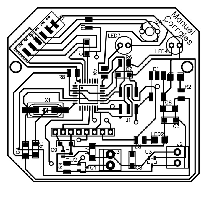
I make some corrections to the PCB because some traces were to close and i have to condiser that the RFID has to be a little far away from the LEDs connections. I draw the lines that measures the position of the LEDs and that of the holes.
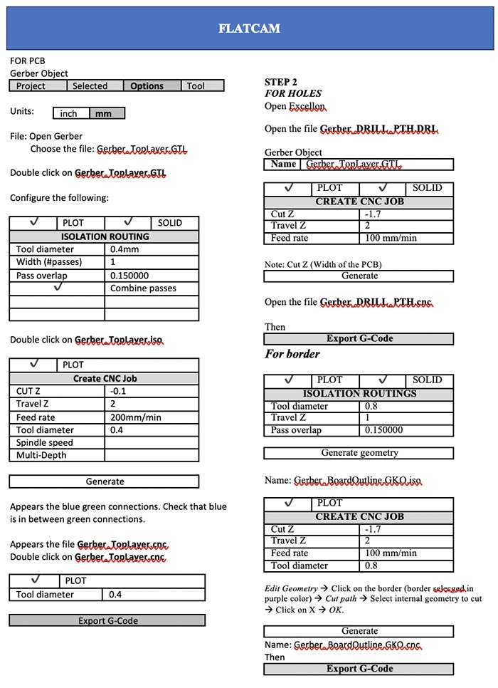
Now the processing of my PCB done in EasyEda by Flatcam First Open Flatcam and in the options section, i select the units in mm. Then i open the Gerber file that contains the information about the Traces. Open Gerber We have to add the configuration of the Milling machine as follows for the traces. Endmill of 1/64
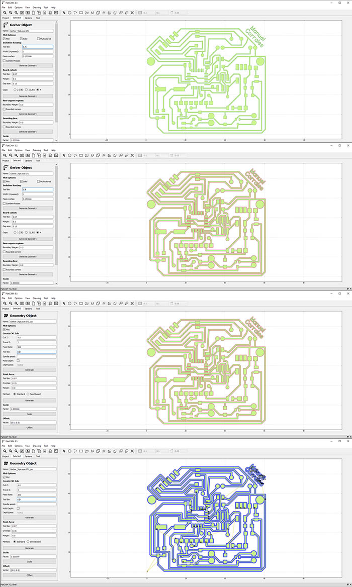
After configurating the traces, i continue with that of the holes. Endmil of 1/32 or 0.8mm
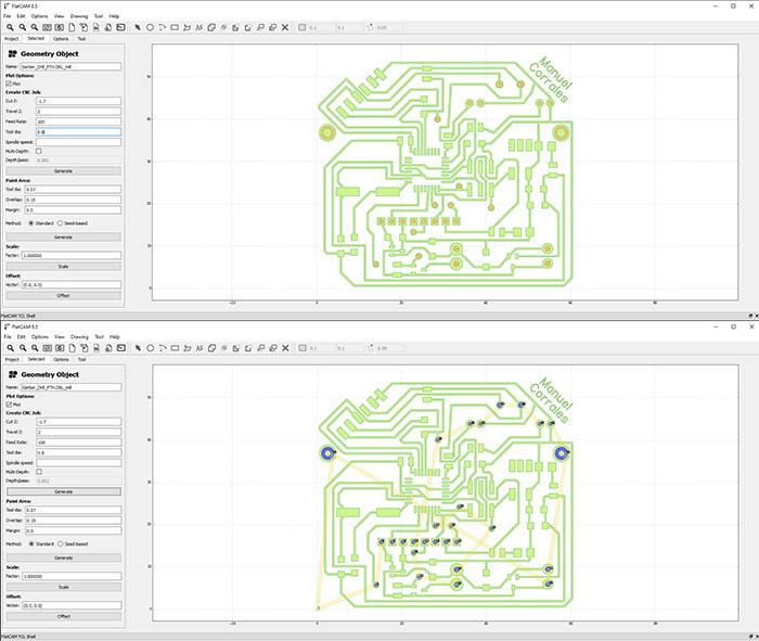
Finally the configuraion of the border. Same endmill as holes. Here some inportan consideration. Due to the geometry of my PCB, that is not a square, i have to do an extra configuration to delete the interior border editing it.
Here i place a Tutorial for Flatcam
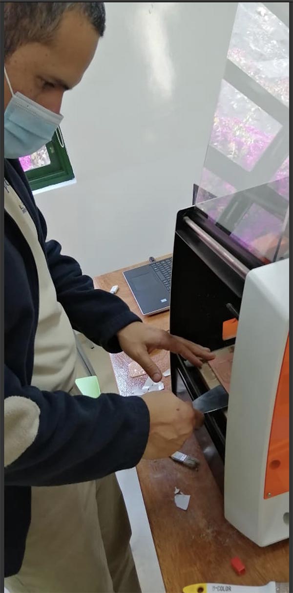
After having all the files for drilling the PCB i use the Milling machine to make my PCB
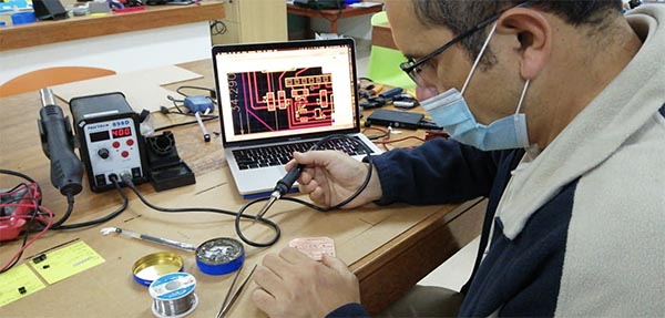
I started the next step: Soldering all the micro components. First place all the electronics in my table, the soldering station, and safety equipment.
After several trials i notice different errors in my PCB, so i did different ones.
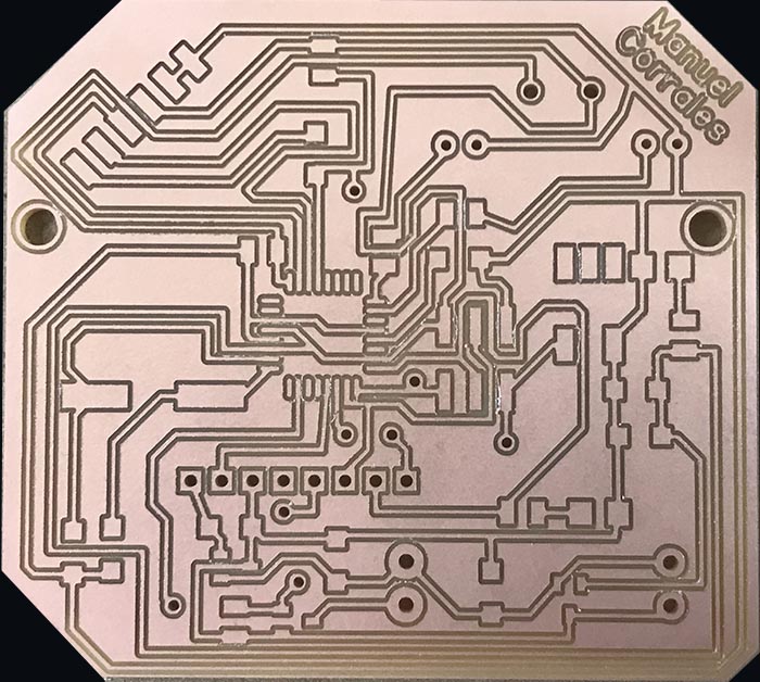
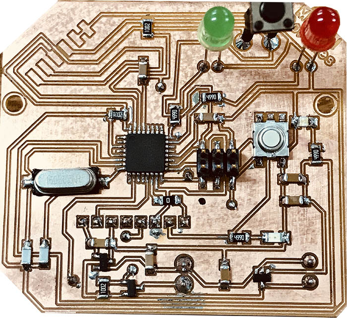
This is the new PCB done where i improve some conections didn´t done. I increase the size of the pads for both terminal blocks which i found important to increaes size making both components tightly fixed to the PCB. I rearrange the Leds and button pads according to the final location in the case.
Then i start soldering all the components. I use the PCB PDF to guide myself.
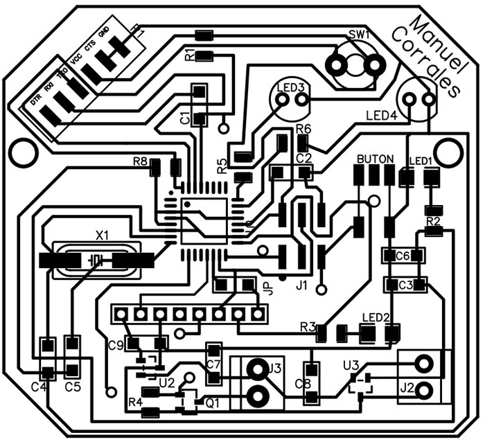
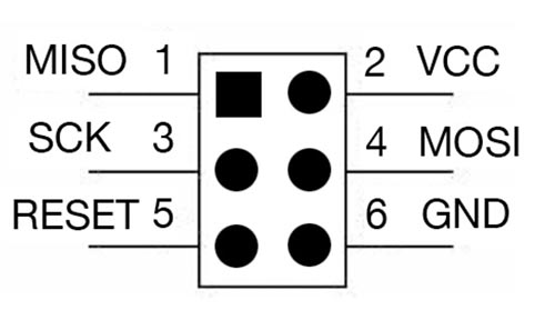
I have to consider some important issues about the ISP conector and the Atmega328
Pins one(1), three(3), four(4), and five(5) all connect to the chip. Pins two(2) and six(6) are tied to power (pin 2) and ground (pin 6).

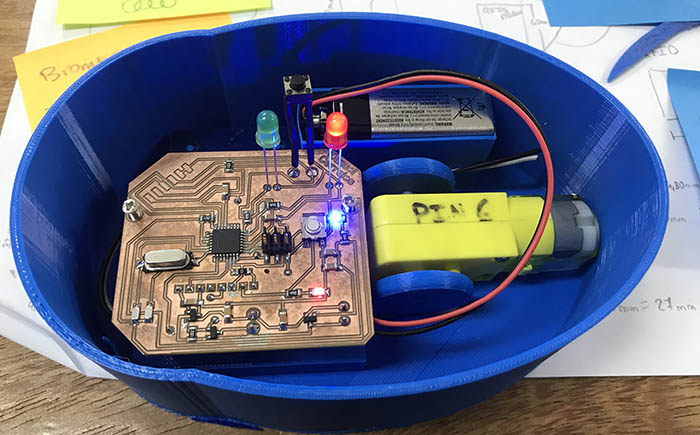
The Final Circuit Board
And the total components that are going to be part of the animal robot.
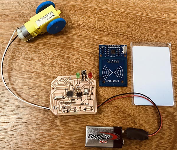
TESTING THE RFID CARD WITH ITS READER IN ARDUINO The RFID reader is attahed to the Arduino UNO and when the White RFID Card is attached to the reader, the blue led turns on.
Testing the Arduino with RFID Reader and Card from Manuel Corrales Arana on Vimeo.
Testing the motor
Testing the motor with the button.
Testing the motor from Manuel Corrales Arana on Vimeo.
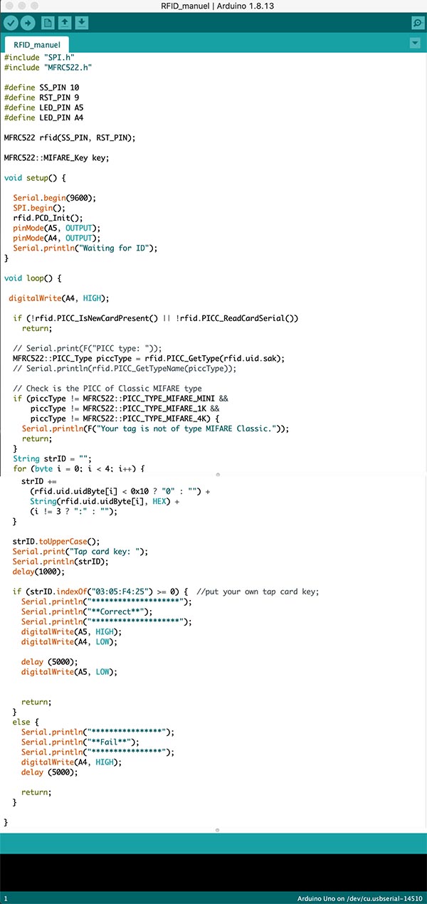
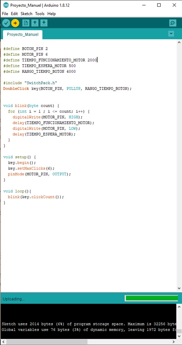
Here the Arduino Code
The complete arduino code with the Debounce included due to the button bounce plus the RFID Libraty and the gear motor. All in one.
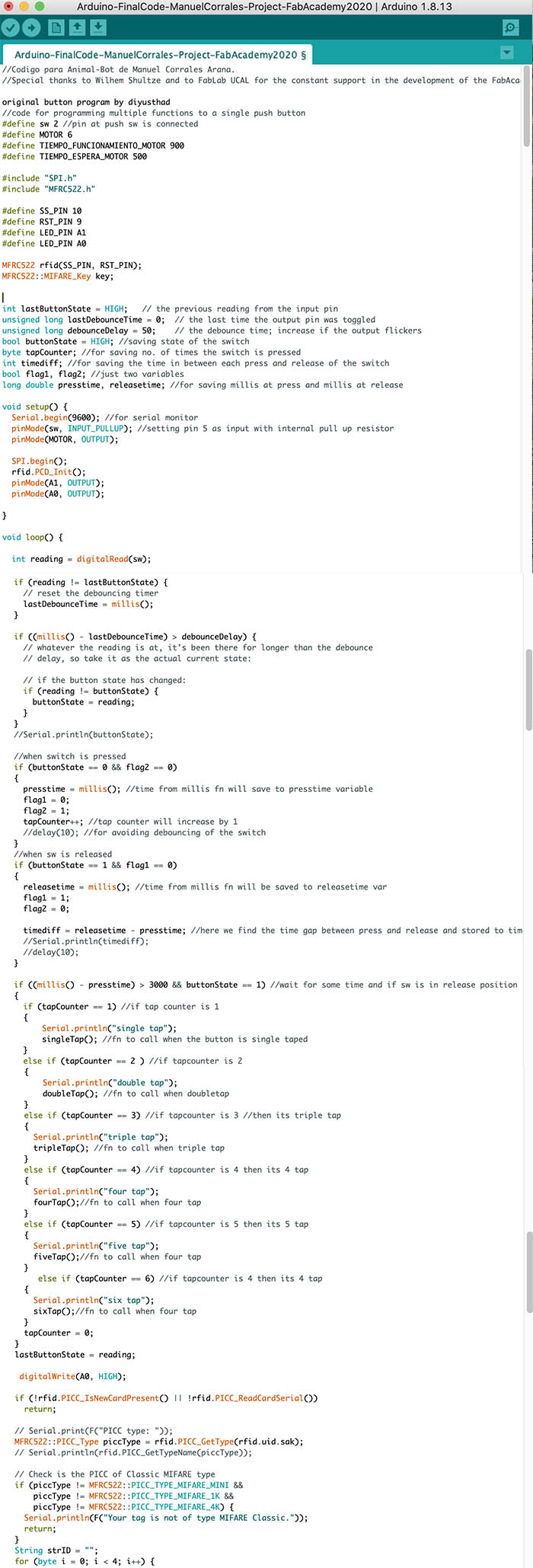
Bug-Bot-ArduinoCode-Debounce + Gear motor + Button
DESIGNING THE INSECT-BOT IN 3D
Sketching of the model
I start to 3D print the two wheels that will be attached to the motor.
I use Fusion 360 to model the animal bot.

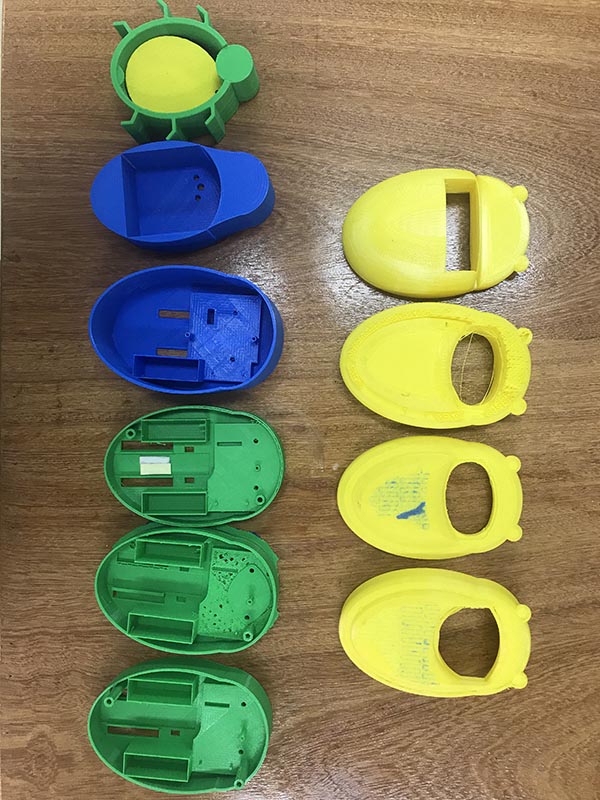
I print the first model to find if the different measurements are well done by assembling the different components.
I noticed that I have to resketch some measurements like the witdh of the hole to fix the wheels.
Then i started printing the lid of the animal bot in yellow color.
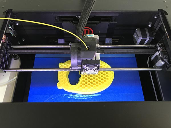
But due to several tests i printed a lot of models and correct different issues in all of them until i finally obtained the structure that will hold the electronics inside with the battery.
Testing the robot where the motor works, the RFID reader read the RFID Card under the base. Now time to improve design.
Testing the motor from Manuel Corrales Arana on Vimeo.
This little robot is my first robot done by myself with the guide of my instructor. Most of the materials where given by the FABLAB UCAL, some of them i bought and some by the Makerspace i lead at Colegio Villa Caritas. The aproximately cost is about $48 in electronic components with PCB. The aproximately cost is about $40 in 3D printing. The aproximately cost in 2D laser cutting is about $4
Find here the STL Files for the two parts of the BUG-BOT
FINISHED PROJECT
Final project - Slide
Final project - Video
Final Project from Manuel Corrales Arana on Vimeo.

Thanks for the great opportunity to work on this. Special thanks to my instructor Wilhem Shultze which supports me a lot and to Luis Perez my partner in this Fabacademy as well as to the facility of the Makerspace at Villa Carita´s High School where we complete this assingment in collaboration with the FABLAB UCAL.
This FabAcademy let me learn a lot of new skills and knwledge in the world of fabrication, as electronics, programming, understand how things are produced, how to assemble, how to do a digital project. All the different processess to build something are completely new for me.
This world is amazing, specially if what i did serve others.