9. Embedded programming
During this week we worked on the group assignment.
Read a datasheet
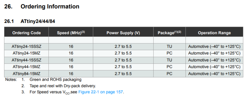
This week for the individual assignment, I read the ATtiny24/44/84 Datasheet
As with all machines used on fab labs, those documentations gives very useful info to work with.
It is practically impossible to read all the info in it but there are specific parts that could be very helpful to understand. It can be used for example in debugging electronics and code, working voltages, power consumption, memory specifications or frequencies are among the important data that those documents give for fabrication of electronic devices based on these microcontrollers.
You can also find drawings and schematics which give the data needed to create footprints if necessary.
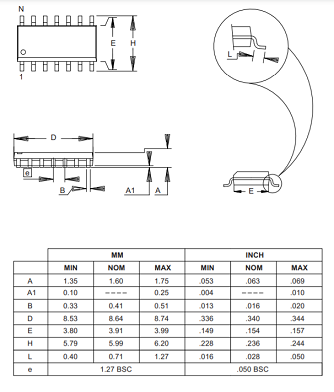
Just to get started, the pages dedicated to pin description and identification could be the most fundamental information that will be used to program the boards. As you can see, pin identification is different for each programming language:


Basic information from the datasheet:
- Operating voltage: 2.7 - 5.5V.
- Industrial temperature range: -40°C to +85°C.
- Endurance: 10,000 write/erase cycles.
- Speed grade: 0 - 8MHz at 2.7 - 5.5V, 0 - 16MHz at 4.5 - 5.5V.
- Four PWM pins.
For this week’s assignment, the other task was to program the board built on electronics design week to do something.
The first step was to upload an already existent example in Arduino IDE with a basic Blink program. I just needed to check the info for the pins and change it in the code to make it work.
Everything worked fine.
Next, I used the blink code Example which was written in C. With this example, I just checked that assigned pins were declared using the adequate format.
//
// hello.arduino.328P.blink.c
//
// test blinking LED
//
// Neil Gershenfeld
// 10/21/13
//

#include <avr/io.h>
#include <util/delay.h>

#define output(directions,pin) (directions |= pin) // set port direction for output
#define set(port,pin) (port |= pin) // set port pin
#define clear(port,pin) (port &= (~pin)) // clear port pin
#define pin_test(pins,pin) (pins & pin) // test for port pin
#define bit_test(byte,bit) (byte & (1 << bit)) // test for bit set
#define led_delay() _delay_ms(100) // LED delay

#define led_port PORTB
#define led_direction DDRB
#define led_pin (1 << PB5)

int main(void) {
   //
   // main
   //
   // set clock divider to /1
   //
   CLKPR = (1 << CLKPCE);
   CLKPR = (0 << CLKPS3) | (0 << CLKPS2) | (0 << CLKPS1) | (0 << CLKPS0);
   //
   // initialize LED pin
   //
   clear(led_port, led_pin);
   output(led_direction, led_pin);
   //
   // main loop
   //
   while (1) {
      set(led_port, led_pin);
      led_delay();
      clear(led_port, led_pin);
      led_delay();
      }
   }
I also modified the blink code example to make the LED fade in and out when the button is pressed. This is possible because the LED is connected to a PWM pin.
The function fade() was added at the end of the code, and it is invoked when the button is pressed, otherwise, the LED is turned off.
*
  Button

  Turns on and off a light emitting diode(LED) connected to digital pin 13,
  when pressing a pushbutton attached to pin 2.

  The circuit:
  - LED attached from pin 13 to ground
  - pushbutton attached to pin 2 from +5V
  - 10K resistor attached to pin 2 from ground

  - Note: on most Arduinos there is already an LED on the board
    attached to pin 13.

  created 2005
  by DojoDave <http://www.0j0.org>
  modified 30 Aug 2011
  by Tom Igoe

  This example code is in the public domain.

  http://www.arduino.cc/en/Tutorial/Button
*/

// constants won't change. They're used here to set pin numbers:
const int buttonPin = 5;     // the number of the pushbutton pin
const int ledPin =  8;      // the number of the LED pin
int brightness = 0;    // how bright the LED is
int fadeAmount = 5;    // how many points to fade the LED by

// variables will change:
int buttonState = 0;         // variable for reading the pushbutton status

void setup() {
  // initialize the LED pin as an output:
  pinMode(ledPin, OUTPUT);
  // initialize the pushbutton pin as an input:
  pinMode(buttonPin, INPUT);
}

void loop() {
  // read the state of the pushbutton value:
  buttonState = digitalRead(buttonPin);

  // check if the pushbutton is pressed. If it is, the buttonState is HIGH:
  if (buttonState == HIGH) {
    // turn LED on:
    fade();
  } else {
    // turn LED off:
    digitalWrite(ledPin, LOW);
  }
}
void fade(){
   // set the brightness of pin 9:
  analogWrite(ledPin, brightness);

  // change the brightness for next time through the loop:
  brightness = brightness + fadeAmount;

  // reverse the direction of the fading at the ends of the fade:
  if (brightness <= 0 || brightness >= 255) {
    fadeAmount = -fadeAmount;
  }
  // wait for 30 milliseconds to see the dimming effect
  delay(30);

}
Other Example
During the lockdown when I had no access to redo the board with the milling machine, I practiced embedded programming using Arduino Boards and sensor modules which I took from the lab as an emergency-kit for practicing during those days.
To understand the process of integrating and programming more than one peripheral connected to a microcontroller, I received an explanation for help. I was interested in working with the sensors that I want to include in my final project. Arduino IDE works by blocks, so the first step is to include all the libraries that we are going to need for the whole project and define variables.
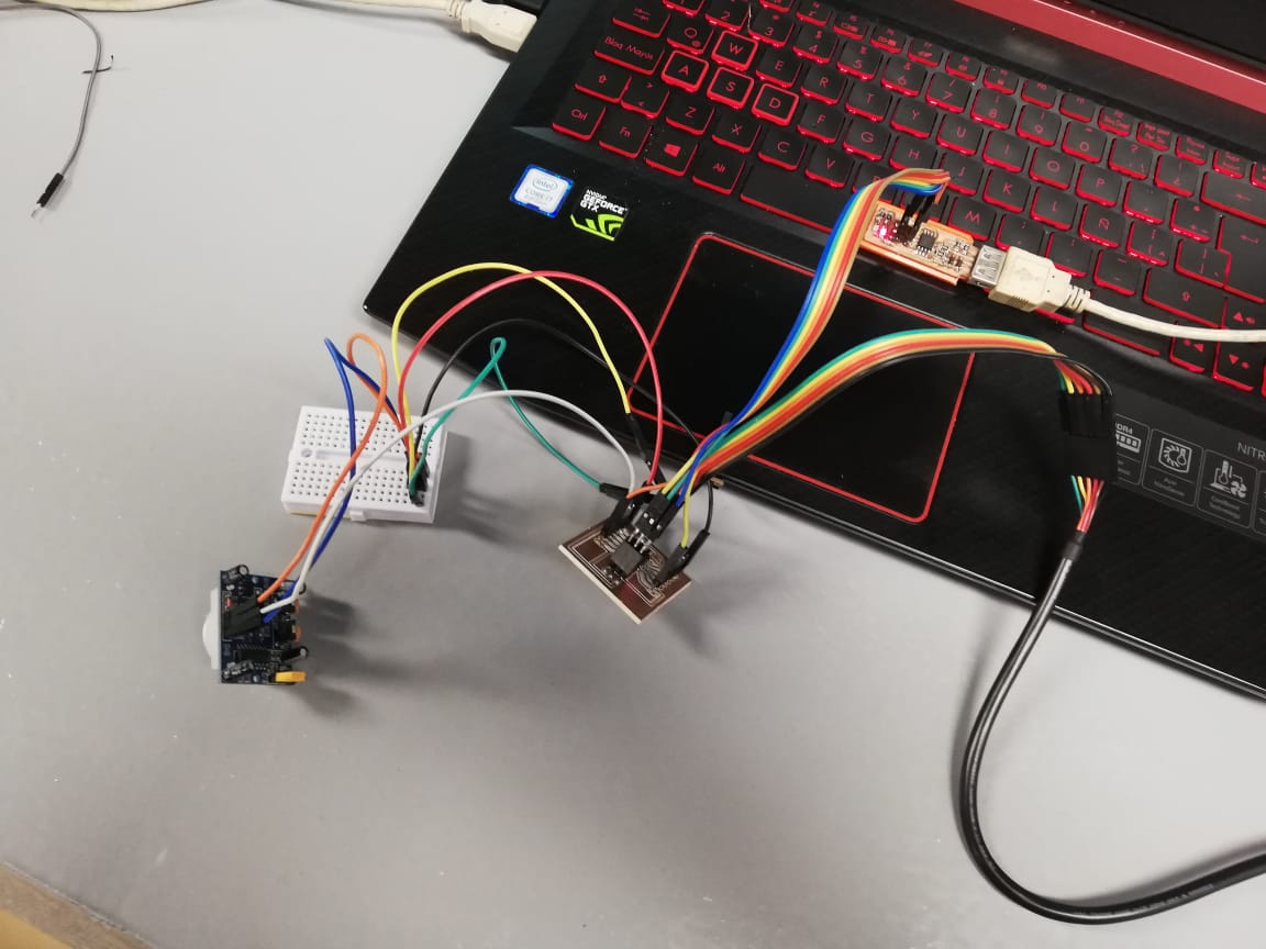
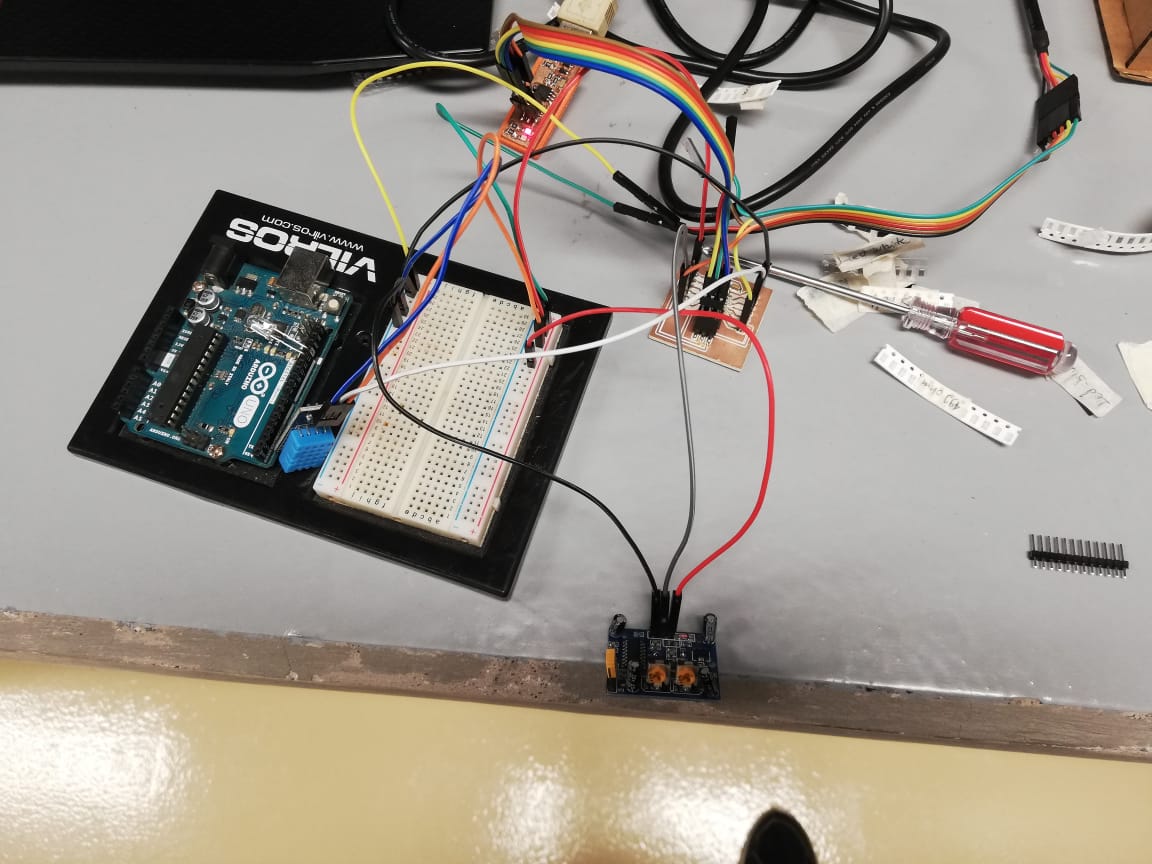 This is my board with the two sensors connected (note that the arduino is there only because of the protobard attached to it.).
#include <dht.h> // This is a library for temperature and humidity DHT sensors
#define dht_apin A0 // Analog Pin sensor is connected to
dht DHT;
int ledPin = 13;                // LED
int pirPin = 2;                 // PIR Out pin
int pirStat = 0;                   // PIR status
// This are the variables for an Infrared motion sensor
Then comes the setup, where serial communication is started and pin modes are set (input for sensors, output for actuators).
void setup(){
  Serial.begin(9600);//serial communication for board and sensors
  delay(500);//Delay to let system boot

  pinMode(ledPin, OUTPUT); //The mode of the LED pin connected to pin 13 of the Arduino Mega output
  pinMode(pirPin, INPUT); // The mode ot the PIR sensor input
  delay(1000);//Wait before accessing Sensor
}//end "setup()"
Finally, the loop block is, by definition, executed continuously, and following each function and step in the specific order set in the code.
void loop(){
  //Start of Program

  pirStat = digitalRead(pirPin); //value of the reading assigne to pirStat
  if (pirStat == HIGH) {            // if motion detected
    digitalWrite(ledPin, HIGH);  // turn LED ON
    Serial.println("Hey I got you!!!");
    lectura(); //execute lectura() function
  }
  else {        //otherwise
   digitalWrite(ledPin, LOW); // turn LED OFF if we have no motion
  }
}// end loop

void lectura()
{
    DHT.read11(dht_apin); //read input pin
    int temp = DHT.temperature; //read temp data
    Serial.print("Current humidity = ");
    Serial.print(DHT.humidity); //print himidity data
    Serial.print("%  ");
    Serial.print("temperature = ");
    Serial.print(temp); //print temperature data
    Serial.println("C  ");
    delay(5000);//Wait 5 seconds before accessing sensor again.
    //Fastest should be once every two seconds.
}
Note that the function lectura() at the end corresponds to the final line of the if structure inside the loop. This is useful to define some actions that a peripheral may execute in a program, and it helps to have cleaner and more readable code.
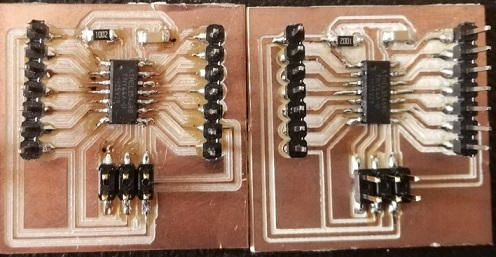
After having access to the milling machine, I practiced and made lots of mistakes in electronics fabrication, until I got a functional PCB. Because of the lack of time, I worked on a PCB which incorporates an Attiny 44 with pins to practice in some of the following assignments.
I learned that for programming a microcontroller like the Attiny 44 or even an UNO or MEGA 2560 boards using Arduino IDE, it is useful to start by reviewing the datasheets and use that info for setting the code. Information like the reference for each pin, their functions and features are important for the programming. I think that pin configuration could be the main reference to use it as a guide for circuit connections and embedded programming.
When testing the board I designed, I understood the importance of identifying VCC, GND, MISO, MOSI and other pins for connecting and programming the board. This PCB must be connected to the computer through the ISP programmer that was fabricated on the individual assignment of electronics production week. The board must also be connected to the computer through the FTDI cable for serial communication.
I learned that the difference between programming a commercial board as the UNO and my board is mainly in the fact that the UNO board includes circuits for serial communication, usb programming, voltage regulators for external electric power, and others.
So, as I was interested in transfering the code made for the UNO, I learned that it could not be done without some modifications because my attiny44 board didn’t have the same serial communications capability, and it was necessary to work with a library called “softwareSerial” instead of the common “Serial” used in the UNO example.
Files