3. Computer Aided design
During this week, I explored some of the software proposed on the site. I test at least one of each type but I am aware that there are a lot of options and it is important to continue testing all of them to decide what are more suitable for my interests.
2D Design
For raster images, I decided to start with GIMP, once the software was already installed in my computer I followed a pair of tutorials available on the page written by Pat David specifically I followed the GIMP Quickies and the Simple floating logo.
At this example, I applied the “Flip tool” both vertically and horizontally.
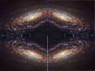
Then I explored how to make a floating logo varying diffusion values and adding different layers and backgrounds
 ,
, 
Inkscape
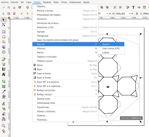
For 2D design, I also explored INKSCAPE software, I found some useful things that I can do with this tool. For example, I found some interesting models in a book to make cardboard kits to teach and learn about molecular geometry. So I can use this software to take advantage of an image scanned from the book with a mobile app.

Some basic tricks that I can Apply are cut it to remove the watermark, using ctrl+F6 to (Draw calligraphic or brush strokes) to make a closed-form, then select and raised it to the top in the object tab, then select both images and in the same tab go to clip option and press set (this should cut the first image with the form of the top one).

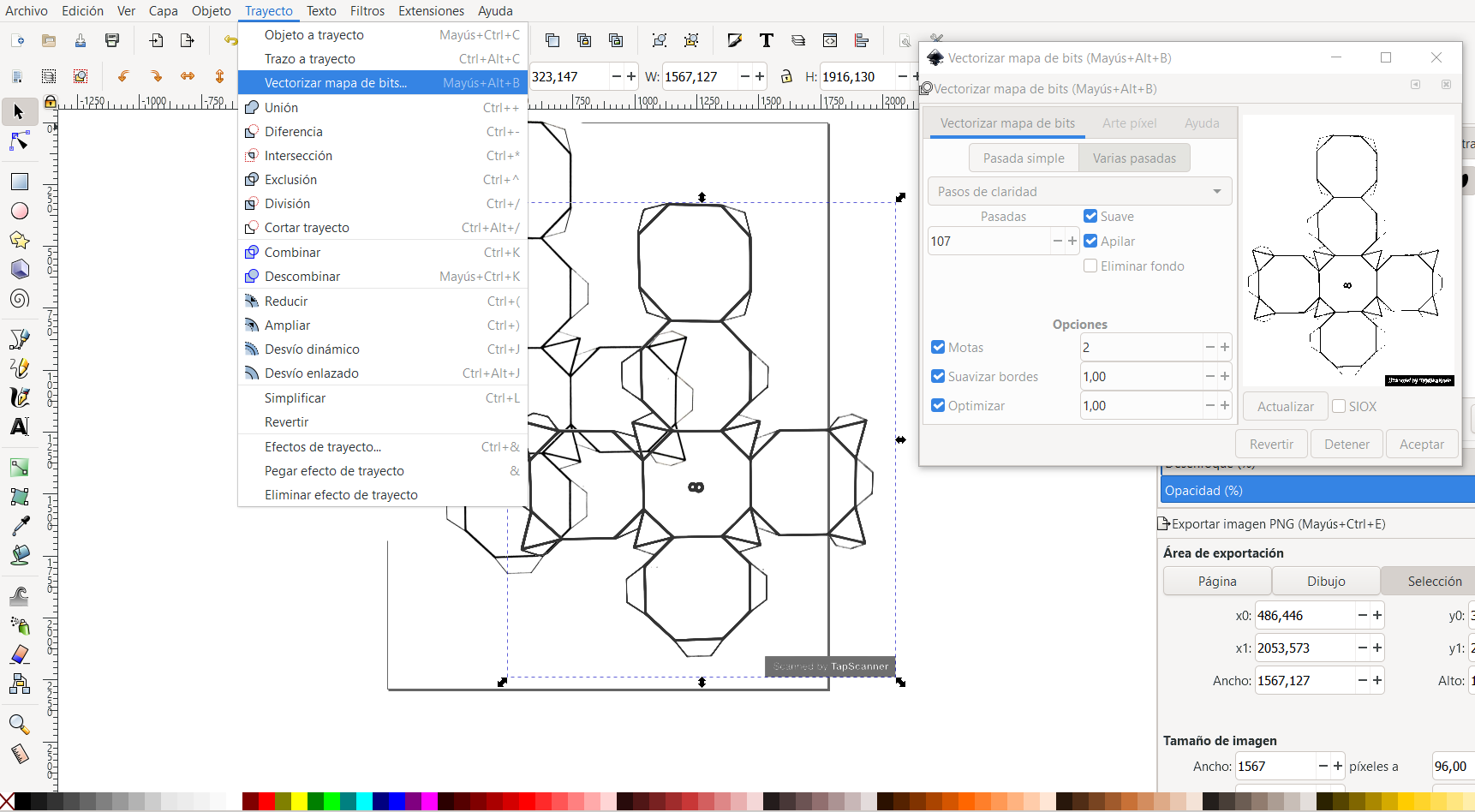
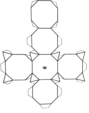
Another useful resource that this software brings is the option of Trace bitmap, which is useful to trace the images for cutting in vinyl or laser cutting machines, this option is in the Path tab, and is possible to modify the edge detection, in addition to the number of passes among other options to obtain a good bitmap for cutting (I changed the number of passes to improve the visibility of all the lines in the result).
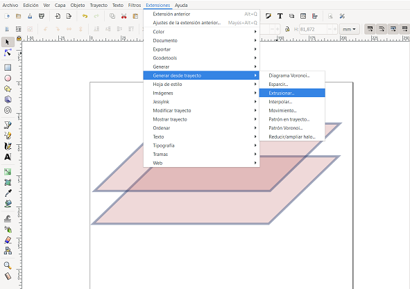
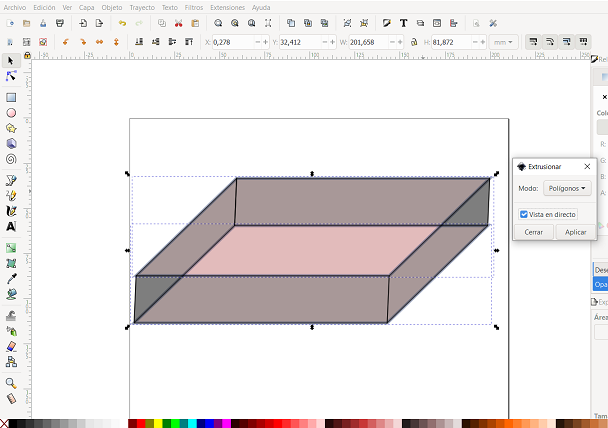
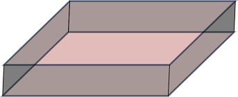
This software also gives the possibility to design “3D images” from 2D using extensions, I followed this demonstration to use the extrude option in the section generate to the path in the extensions tab, after using the option object to path in the path tab.
Files
3D CAD
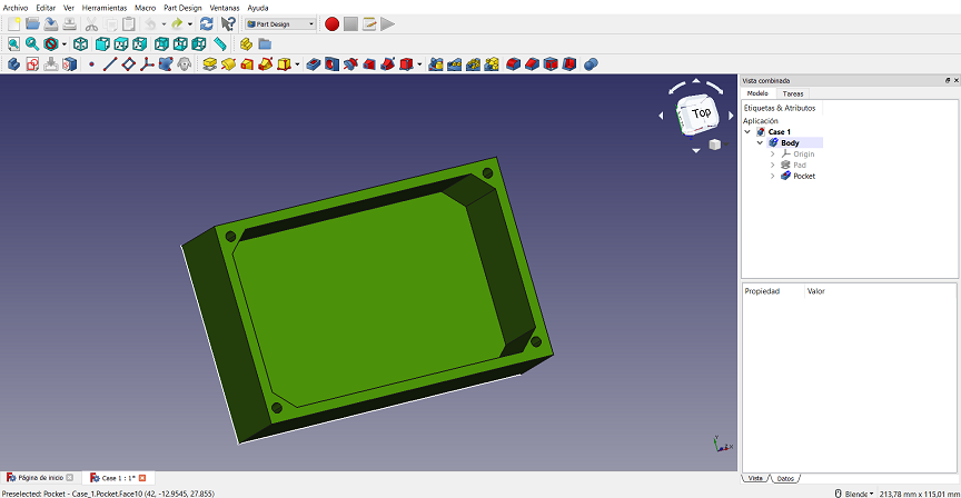
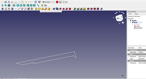
My first steps in 3D design were on FREECAD, in the same idea, I start learning about the “part” and “part design” workbenches.In the part workbench, it is possible to create 3D bodies form 2D sketches, then can be applied actions that let make holes or cutouts based on other sketches situated at the faces of the 3D form. Making 3D designs from sketches gives the chance to use the Spreadsheet workbench where you can define functions that can be used to parametrize specific parts of the sketch using constraints. I followed this tutorial, to learn how to make a box that I could use then to modify it and take advantage of it in the final project.

Another utility that I learned with this experience is that I can use the revolution operation to project in 3D a sketch around an axis. You can decide around which axis the revolution will be, and also the angle for the projection.
 There are other operations that let modify the borders of the 3D forms which is useful to improve the aesthetic of the design too.

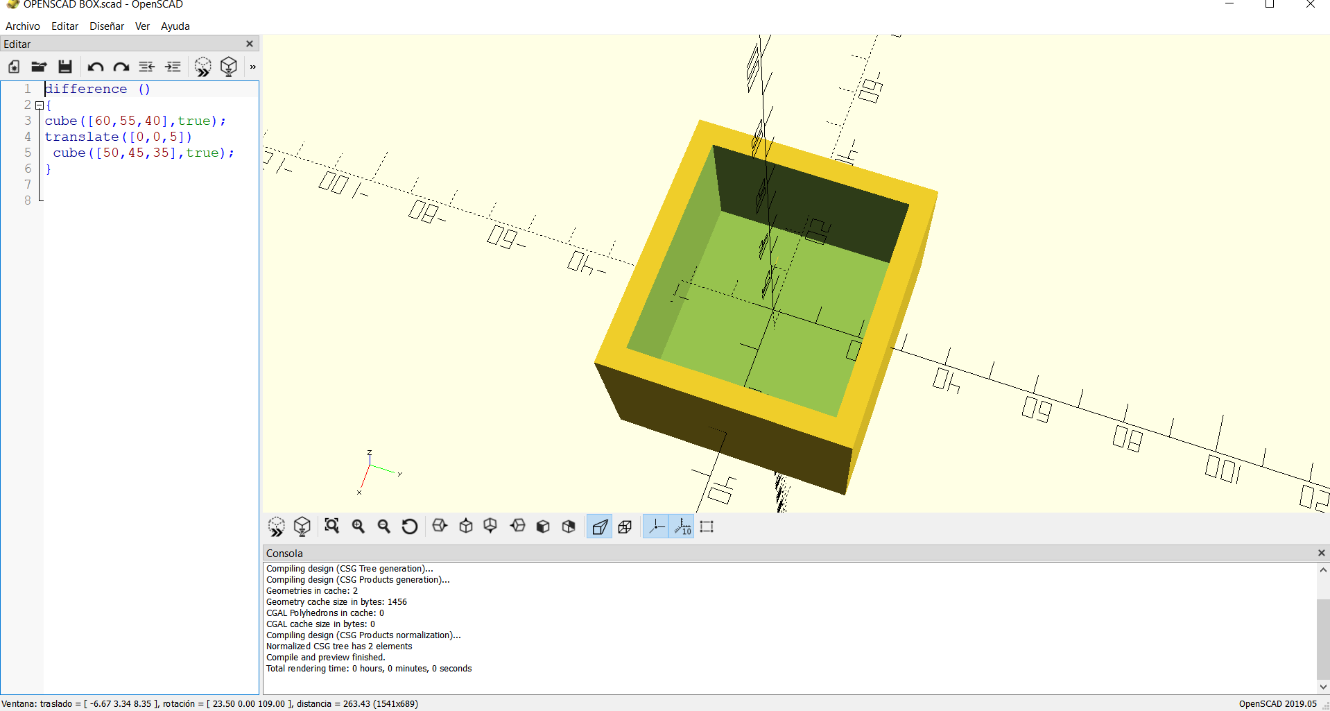
The other Software that I tested is OPENSCAD, this open resource works with parametric 2D and 3D design too, but instead of clicking buttons is possible to render solid objects using specific programming commands and functions to modify them.
A good point with this tool is the documentation such as the Cheat sheet and tutorials available in the page.
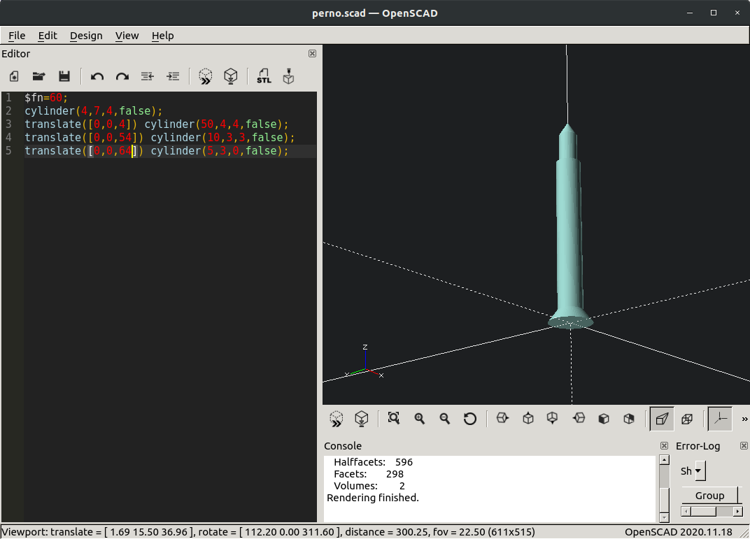
So I decided to also design the cap screw from my case (which I designed previously using FreeCAD).
OpenSCAD is very particular because the design is entered in the software in the form of written code. Actually, the cap screw design for OpenSCAD looks very simple:
$fn=60;
cylinder(4,7,4,false);
translate([0,0,4]) cylinder(50,4,4,false);
translate([0,0,54]) cylinder(10,3,3,false);
translate([0,0,64]) cylinder(5,3,0,false);
The interpretation of each line of the code is:
-
number of facets used to generate an arc
-
create a cylynder [height,rad 1, rad 2, center attr]
-
create a cylinder and translate it [in z]
This is the result:
I also tried OpenJSCAD, an in-browser online version of OpenSCAD. The code can be entered the exact same way and it will render the design:

The design can be exported to different formats.
Files