10. Input devices
During this week we worked on the Group Assignment
Since we can´t get any access to the lab, with the Arduino boards and some sensor modules that I took from the lab as an emergency kit, I read about ones of my interest, how they work, and the libraries required to use them.
I followed the workflow described in Electronigs design for the two boards I designed and fabricated for this week.
I was very interested in those that would let me read environmental conditions such as temperature and humidity since I was planning to include a sensor of this type on my final project because those external conditions could affect the performance of a trap camera which is outside in a forest or a jungle ecosystem, exposed to the sun, the rain or snow.
First I cheked the data shet for DHT11 sensor.
I also read about and was interested in testing the motion sensor because the existing commercial trap cameras options include those types of sensors as the most usual trigger mechanism.
As the assignment for this week was to add a sensor to a microcontroller board that I have designed to read it, I took advantage of what I learned in the embedded programming assignment, this is, how to add more than one sensor to a board and reading it.
I designed a board with an attiny44 microcontroller, and put pin headers for each pin so I could eventually connect any device I needed to test.

I connected a temperature-humidity and a PIR sensor to my board.
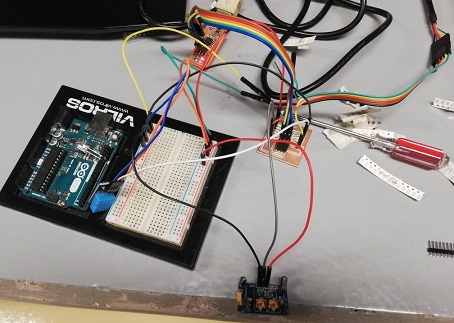
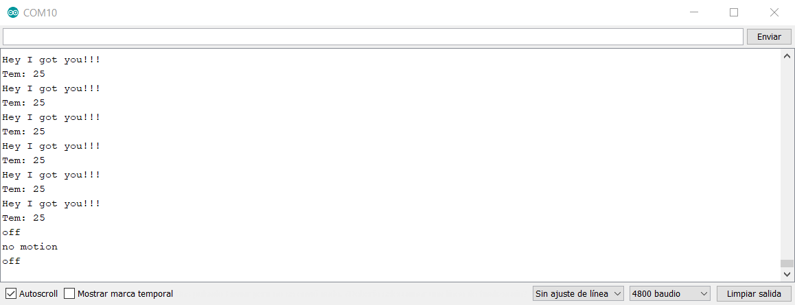
Then, modified some code examples to create a routine to detect motion, then, read temperature and humidity. This is, when there is motion, the microcontroller will retrieve the temperature information from the sensor. In the example, every time the device detected movement, it would display a message (“Hey I got you!!!”), then it would read the temperature and display it (in Centigrade degrees).
ESPCAM32
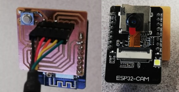
As soon as I received the ESP32 CAM Module, which is going to be added to my final project prototype, I proceeded to work in an input device exercise and I designed a board to facilitate the process of uploading programs to the ESP32 board.
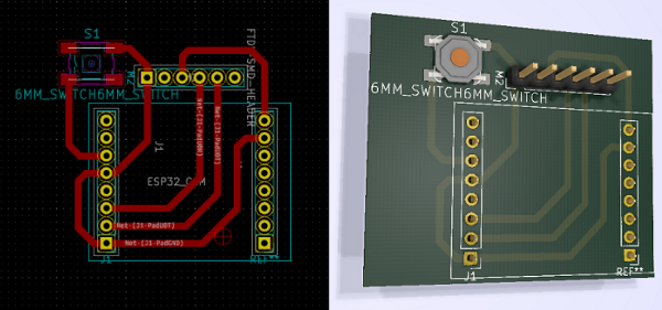
For this, I created a new footprint in KiCAD to connect the ESP32CAM, this board must include pins to connect the module, a button to bridge IO0 and GND pins (this must be pressed during the uploading of new code to the board) and a 1x06 male pins header to connect the FTDI cable.
To create the footprint, the length between the pins of the ESP32CAM was measured, then I included two 1x08 pin headers and separated them by the measured distance. With the instructor’s help, the references of the pins were inverted, this was made planning that the pins of the female connector were soldered from the other side of the copper mask of the circuit. Before milling the board, the distance between the pins was checked by exporting the circuit design to pdf and then printed it on paper to test the dimensions set in the footprint.
To avoid the problems I had with weak soldering joints on past boards, our partner Alex suggested the idea of drilling holes in the board to better attach the pin headers to the board and avoid breaking copper traces. For that, once the board design was done with kiCAD, it is necessary to generate the drilling files, then open them in Flatcam, set up the parameters of the tools as I learned in previous assignments, and generate the code that will be sent to the milling machine.
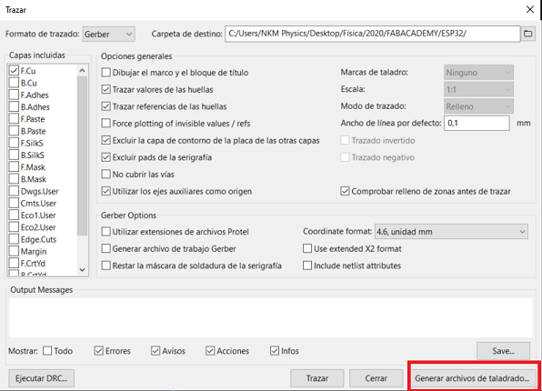
For importing the drilling files in Flatcam, go to File–> Open–> Excellon, then set the right parameters for the machine and tool and export to a file.

This has been very useful because the soldering process of the pins has become easier and the board is stronger for manipulation and connecting and disconnecting peripherals.
After that, I uploaded the code for streaming video in a webserver. It must be taken into account that the reset button in the ESP must be pressed every time new code is going to be uploaded. Also for this board design which has a button instead of a switch (like Neil’s example), one must maintain it pressed before pressing the reset button in the ESP32 and during the uploading process.
In Arduino IDE go to File–> Examples–> ESP32–> Camera–> Camerawebserver. On that code, you must set the credentials for the wifi connection. Also it’s necessary to change the module to AI thinker. At the end of the uploading, open the serial monitor and press the reset button, it is going to display a message with the server address, then copy and paste it in a browser and you can visualize the streaming video.
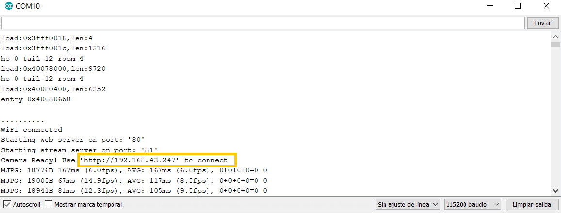
Finally I was able to see the video stream from the board in my computer screen.
