4. Computer controlled cutting
This week we work on the group assignment.
This week’s individual assignment was to design and cut a press-fit kit
First of all, there is general information to take into account for this week’s practical work-related with machines workflow.
Laser Cutter
- turn on the power source
- turn on the machine and the laser
- place the material on the bed (max area 100 cm x 80 cm)(max thickness 10 mm)
- adjust the focus of the laser (laser head height) and set the origin.
- load the design to the software smartcarve
- assign colors to the traces (along with power and speed specifications)(3 mm mdf power 65 speed 20)
- mdf may produce harmful fumes, so it is important to let the machine ventilate well before opening.
- always pay attention to the machine while working.
Vinyl Cutter
- turn on the power source.
- lift the pinch rollers and insert the adhesive vinyl.
- define the origin.
- software Artcut2009
- adjust the size of the design and make sure the material has the appropriate size.
- keep your hands and clothes away from the machine while it is working.
- remove excess material and apply transfer tape.
Vinyl cutting
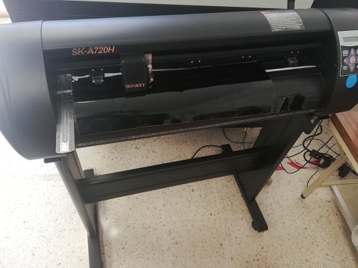
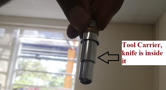
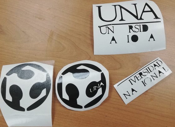
One of these week’s individual assignment was to cut something in the vinyl cutter, the available machine at St.jude is the SiGNKEY SKA720H, here is a page which shows features and relevant accessories of this model.
As this machine cuts the works following the contour of the images, I prepared some examples on Inkscape using the trace bitmap option and grouping all parts of the image.
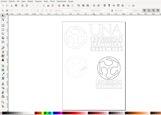
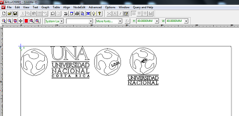
Then was saved it as a DXF file, opened it on the Artcut software, the machine was connected to the computer, the machine was set up using the DSP controller, speed and grammage were adjusted.

Parametric Design (Press-fit kit)

I used Openscad and FreeCAD to get familiarized with parametric design. I worked in this simple example to build a “press-fit kit” considering and then defining variables based on kerf values and other design setups.
FreeCAD
As seen in the third assignment documentation (Computer-Aided Design) the possibility to define functions and then restricting specific parts of a sketch with those values, let to parametrize the designing process and take into count machine capabilities and the properties of the materials used for construction processes. Data acquired from machine characterization can be used to declare functions related to design setups such as kerf or the thickness of the material. As mentioned before,part design workbench let to create an activate a body, the way for begin to make a body in this mode is starting from a sketch, you can use the constraints to make to lines be perpendicular or parallel always or to restrict a length.

Spreadsheet is another workbench in FREECAD, It is similar to an Excel sheet, so the information can sort it using a table format, write an indicator in each row and give it a value in the next column, until here we have just configure the information for us. Now to declare those values as functions to be used for parametrical design, left -click above the cell with the value, right-click in properties, then “Alias” tab, there define the variable with a name to identify it.
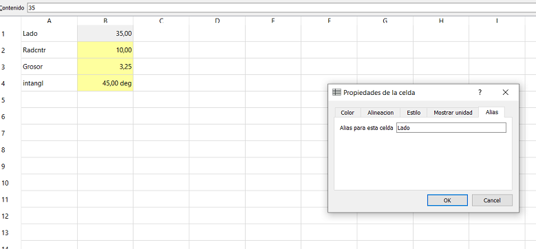
Back in the sketch, double-clicking in a length constraint, click the fx() symbol and call the function using the following format Spreadsheet.” The name that you assigned to the cell with that value in the spreadsheet”. This is a way to assign values that is available in almost every point where must be introduced a numerical value to set up dimensions.

OPENSCAD
The other option of software that I used for parametric design was the OPENSCAD.
This software works as a compiler-based in a language of textual description, when a new project is created there is an empty console in the left side of the window, there is where the code will be written to render images. I recommend checking the cheat sheet in documentation to get familiarized with the commands.
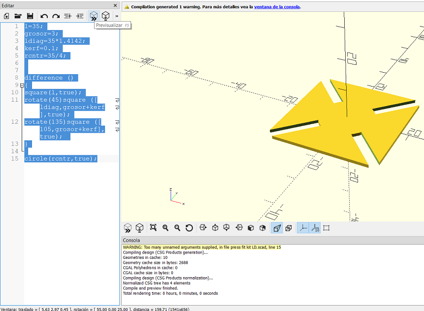
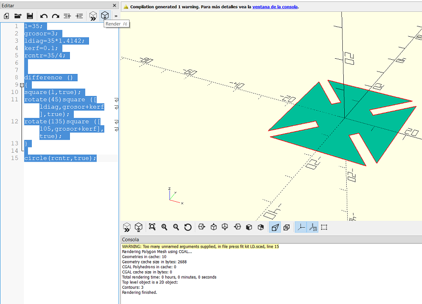
In order, to replicate the same piece worked in FREECAD for this Assignment this code was used.
The first five lines correspond to the definition of the variables, “l” is the length of the piece, “grosor” refers to the thickness of the material, “ldiag” for the line that passes through the rhombus, kerf of the laser cutter was defined in the group assignment in the characterization of the machine.
l=35;
grosor=3;
ldiag=35*1.4142;
kerf=0.1;
rcntr=35/4;
In the next lines, the command “difference ()” is used because a boolean operation will be defined. The next line is to create a square where l determines the size and the true value is to center it in the origin of the tridimensional coordinate plane. those lines also make that square rotate 45° and the central square which is subtracted and rotate 135° where both consider the dimensions define in the previous lines above.
difference ()
{
square(l,true);
rotate(45)square ([ldiag,grosor+kerf],true);
rotate(135)square ([105,grosor+kerf],true);
}
The last line of the code adds the circle in the center of the piece.
circle(rcntr,true);
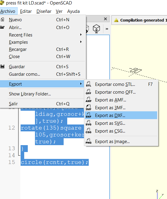
Once the code is ready is necessary to previsualized the model, if everything goes well the result would appear on the right side, finally, it has to be rendered (a sound and a color change are generated if everything goes right), now you can export the file, the software allows different options but I used the dxf extension.
fILES