8. Computer controlled machining
Using LibreCAD is very simple, it is comparable to drawing with pencil and ruler. You use basic shapes (points, lines, circles, rectangles, etc.) and apply simple concepts and processes (parallel lines, rotation, intersections, mirrors, etc.)
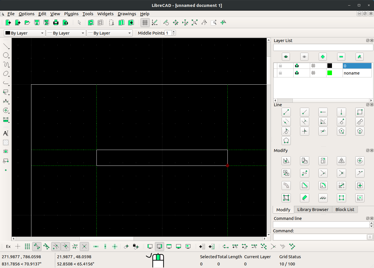
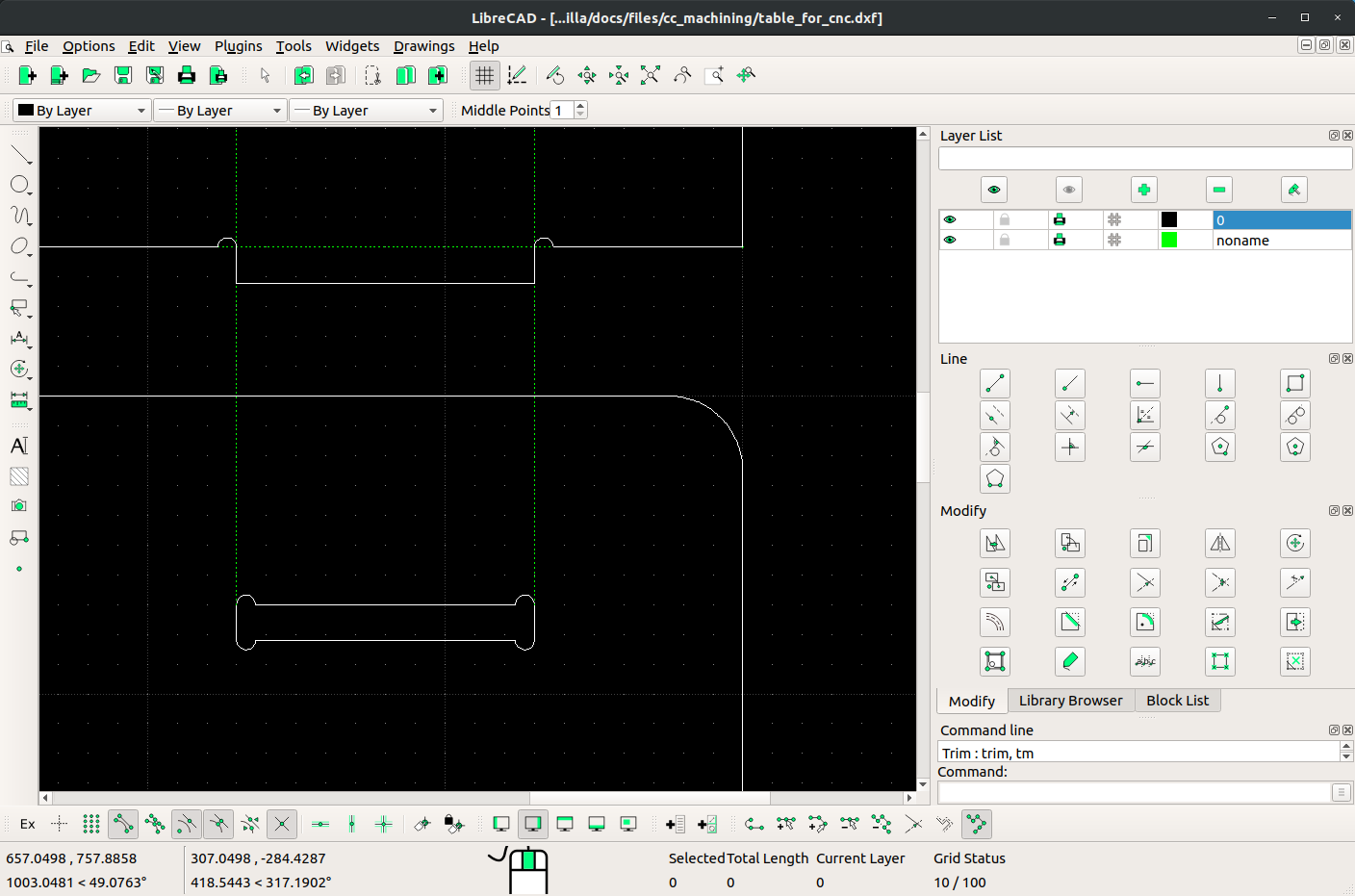
I started with a simple rectangle (table top) and drew the rectangles for the press-fit joints. For this I had to know the thickness of the board. You can use guide lines when drawing. Usually, you create another layer with a different color and/or line type.
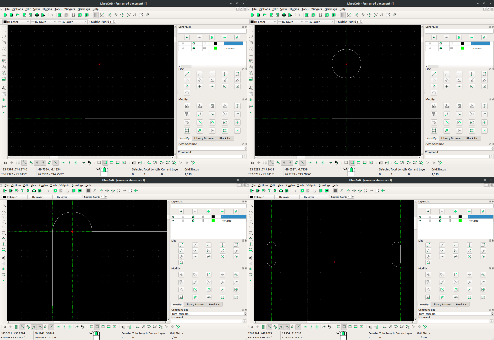
The press-fit joints must be designed with the cnc specifications in mind, mainly the diameter of the tool for the t-bone shapes for the inner angles. For this, a semi-circle is drawn on the inner corners of the design, so that the tool will overcut and the joint will fit correctly.
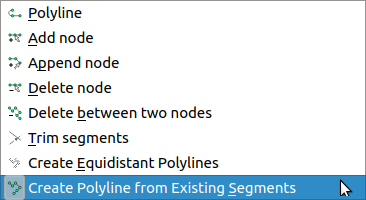
Every time a shape is finished, it is a good practice to convert to a closed shape (this is for LibreCAD users, not sure about other software). For this, select the shape and go to Tools >> Polyline >> Create Polyline from existing segments.
After one bone is created, it can be mirrored, copied and/or moved to create the other ones.

Corners can be rounded with the fillet tool, and new guide lines can be used to create the second press-fit part on the legs of the table. Note that the inside corner of the press-fit tab of the legs must also have a bone shape.
The rest of the shapes can be made by mirroring and applying the fillet tool to soften the corners.
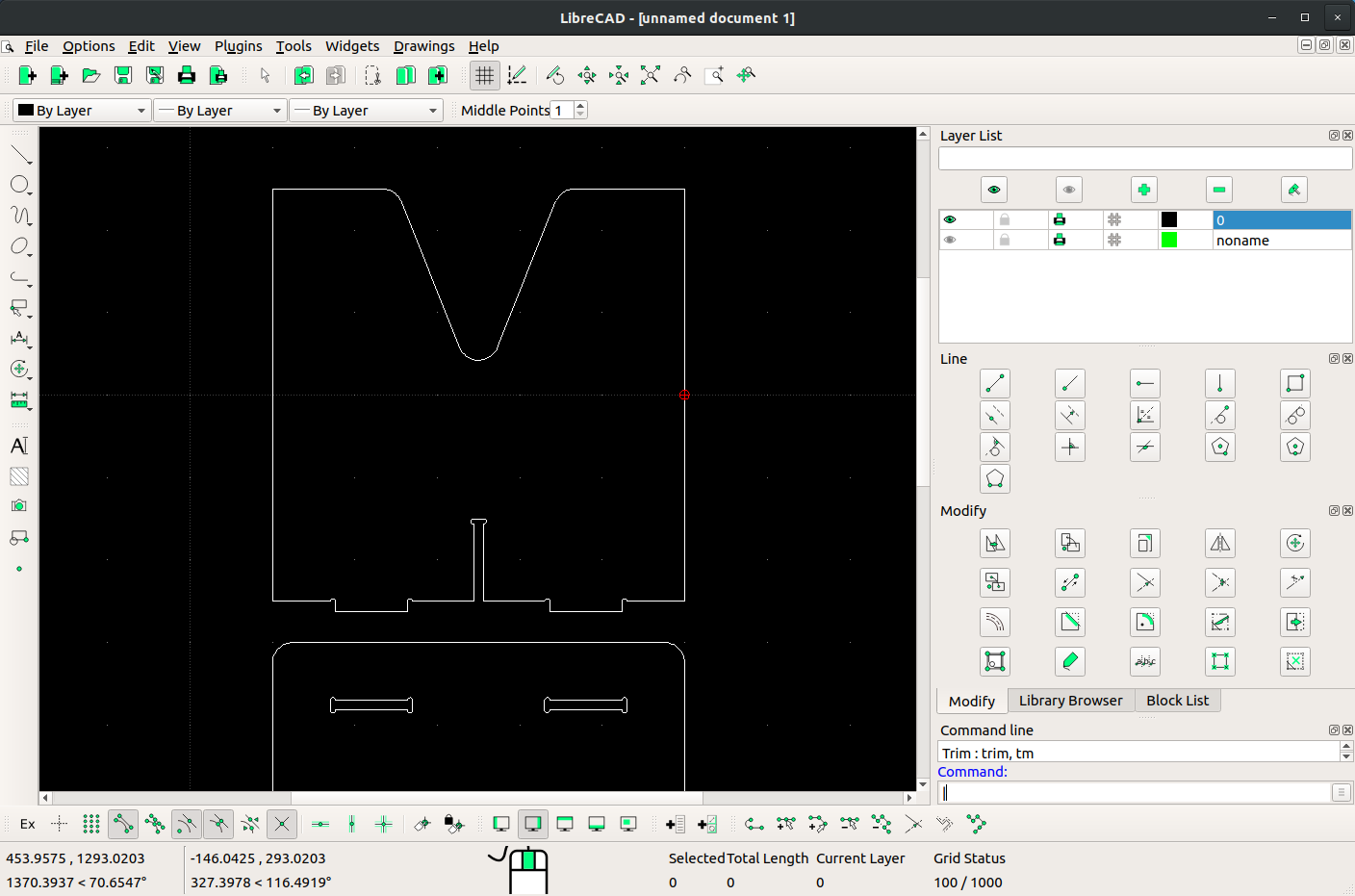
A central piece was added for support of the top part.

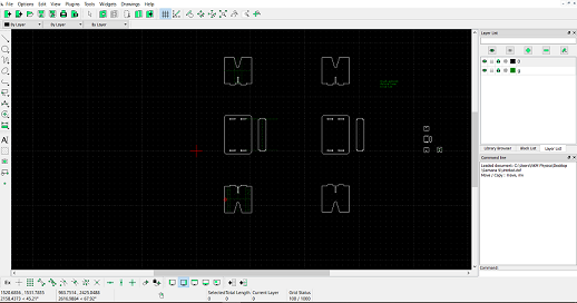
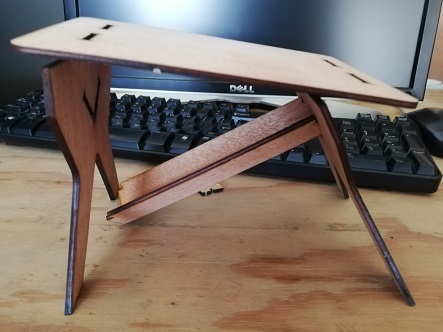
A basic table design:

The next step was to scale the model to cut it in the laser cutter using cardboard, this is a useful practice because it allowed me to identify some issues related to stability and dog-bones dimensions.
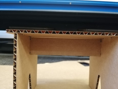
I went back to LibreCAD and changed the design in order to give more stability to the table. Once again I tested it with a laser-cut model and there were more things to improve “this is the reason why it is a useful practice”
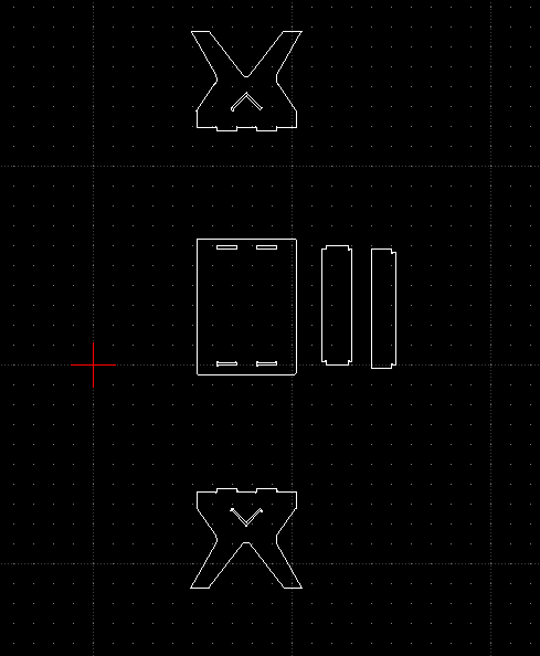
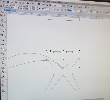
The milling machine I used for this assignment is located at Fab Lab Veritas. It is a good practice of this lab to check the files with Corel Draw before sending it to CAM software, here I identified other issues to be fixed.
The software used to generate the .cnc files was Artcam.
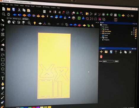
These are steps to create the CNC files:
-
Open the design file in ArtCAM.
-
Go to Toolpaths
-
Select the profile side (inside or outside)
-
Set start and finish depths
Other settings
-
Tool diameter: 6.350mm
-
Feed rate: 1500 mm/min
-
Spindle speed: 15000 rpm
-
Stepdown: 6 mm
-
Material thickness: 12 mm
-
Material Z zero: top
-
Define the tool profile
-
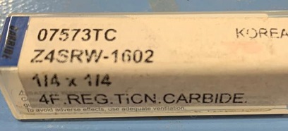
For this work a cut 1/4” tool was used
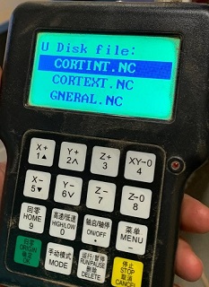
Once the parameters were set up without errors, the tool paths were saved in a USB memory. Three files were saved: one for the inside toolpath, one for the outside and one for a general (corresponding to the tabletop).
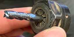
To prepare the CNC machine the steps to follow are: Installing the tool in the collet, attaching the material to the bed using clamps or screws and setting the zeros for all axes.
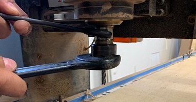
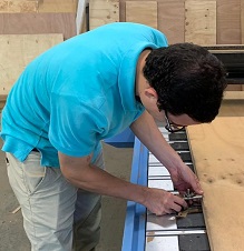
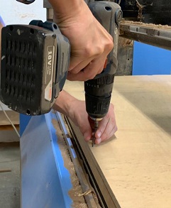
It is important to make sure everything is well adjusted and tightly attached when working with this big machine.
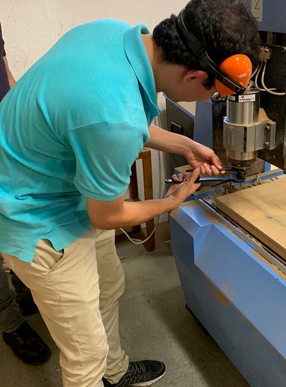
It’s necessary that the tool is firmly installed, this is the one implemented for this job.
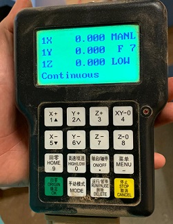
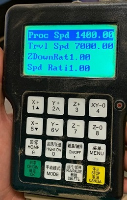
The control is used to set the zeros and adjust parameters related to process speed and travel speed, and finally, once this is ready, to start the job.
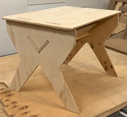
To assemble the table has been necessary to use a rotary tool to smooth the edges of the joints and a mallet for the optimized press-fit.
Files