6. 3D Scanning and printing
During this week we worked on the group assignment.
3D printing
During this week one part of the assignment was to make a 3D design that cannot be made subtractively, some simple examples that can’t be easily made with subtractive fabrication such as laser cutting or other cnc tools, common examples which can be made easier to build using additive fabrication are those whose include transversal holes.
Some machines are able to work in more than three axes but if not it’s difficult to achieve this kind of finish because of the tool freedom and material’s thickness. The first model I worked in was a joint for a distillation flask. To achieve it I used Freecad Part design workbench to build a cone and then applied the hole option to the part.


Then, following with that individual assignment I designed a piece such as a little modular pipeline system that would be useful for prototyping and design machines that include hydraulics applications.
This kind of Designs can be made using boolean operations to union and differencing basic forms like cylinders in any CAD software.
I made it on FREECAD’s “part” workbench.
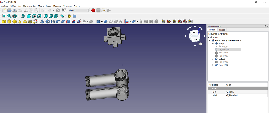
This video was very useful for me to understand how to design screw threads using parametric geometry primitives and swept options.
I printed the model using the Formlabs Draft Design.
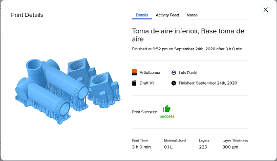
After approximately 3 hours of printing, a washing cycle with isopropyl alcohol for 5 minutes, and a UV light curing of about ten minutes. After removing supports, and a little sanding with a Dremel moto tool, I got these results.

3D Scanning
I had the chance to look working one Sense 3d scanner at Fablab Veritas, we identified that is difficult to scan white or black objects.


Photogrammetry
I tried a Photogrammetry experiment using a Nikon D5600 camera with an 18-55 mm lens, moving it manually with a microwave plate using a white background.

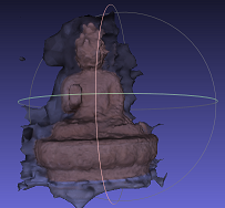
After more than a hundred photos shooted , one each 15° of rotation I used them to charge it in Mushroom software that works calculating first a cloud referencing points to render a mesh, as the data comes from pictures the software generates different files, so it’s possible to acquire the texturing of the scannings.
Actually, I didn’t get the best results, there are various causes for that, first, probably I didn’t was enough careful taking the photos (move the object manually is not the best method), also the white background and light conditions neither was the best option for photogrammetry.
Obtained results for this process can then been opened in meshlab software to improve it as much as possible, here are the best I could achieve.

Files