13.Interface and Application Programming
As this week’s assignment was to write an application to interface an input &/or output device with a user.
I was interested in using the HC-05 Bluetooth module to send an order to an Attiny 45 through a cellphone app..
After reading the HC-05 datasheet I learned about useful Hardware and software features to connected to that kind of microcontroller, this fits very well for PIO control
I searched in the Fab Academy search engine if somebody has made something similar to use it as a guide, I found this documentation which helps me to understand how to connect both components.
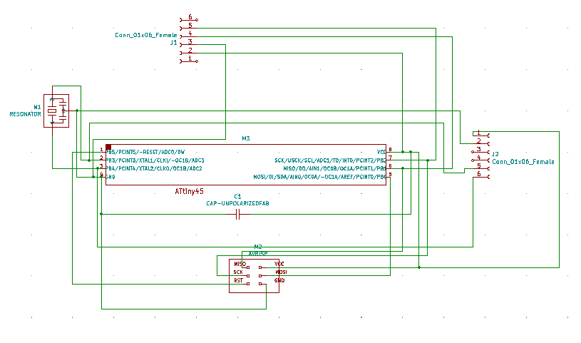
As the module works by serial communication there are going to be used four pins to connect it with the attiny 45.
-
VCC(3.3 -6V) -Pin 8 of ATtiny45
-
ND -Pin 4 of ATtiny45
-
TX -Pin PB1 of ATtiny45
-
RX -Pin PB2 of ATtiny45
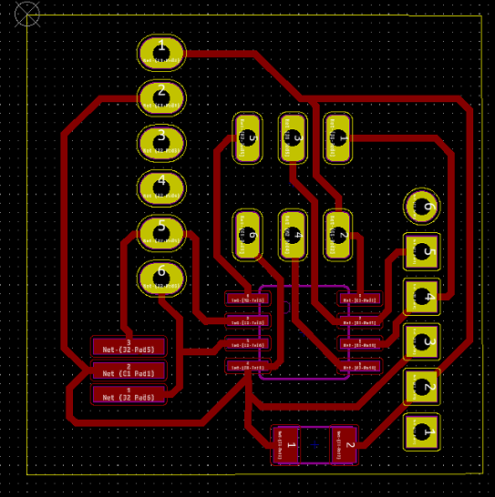
To interface with I/O devices were added two sockets connected to pin 2 and 3 of the Attiny (PB3 and PB4).
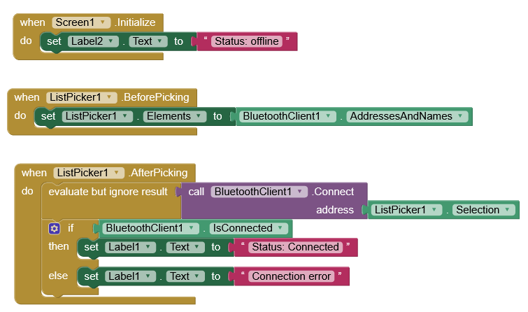
Then the application was written using MIT App Inventor, I reviewed MIT tutorials available in the website such like this. App Inventor let to build applications for Android using a designer interface where different objects can be added (including a hidden Bluetooth client function) there is also a blocks section for programming the actions in each of the objects in the interface.

An object called listPicker is used to select the module from a list of available Bluetooth devices and a specific value for the ON and OFF options for each of the pins, in this case, will be 1 or 0.
 The first program prepared in the Arduino IDE and uploaded to the Attiny is the Following.
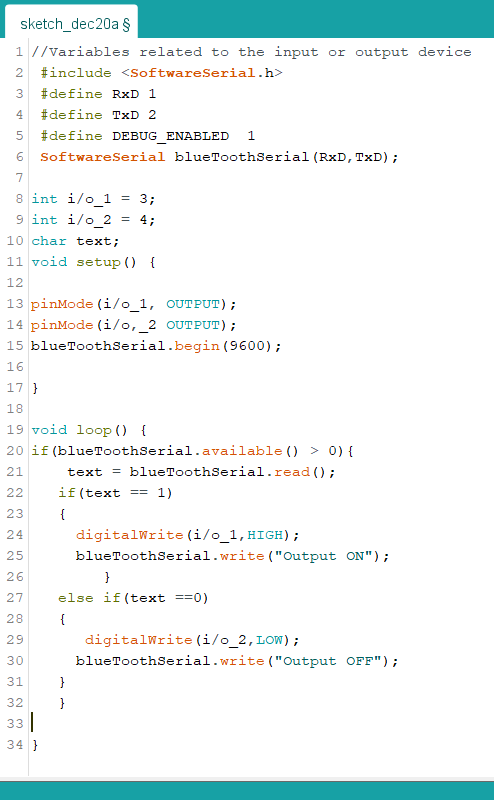 First, the variables are defined, and the needed libraries included, as in the application each button send a text message (0 or 1) will be used a char variable called text to receive the value that will be turning on or off the signal in the pin.
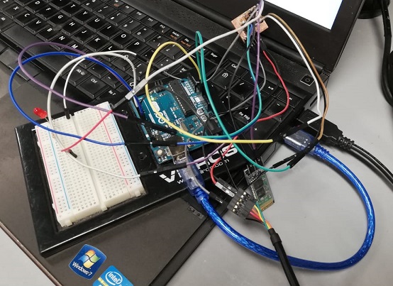
In order to test that the BlueTooth module was sending the pulse to the corresponding pins, I used an FTDI cable to check it in the serial monitor. I had some trouble with my built-in programmer module so I used an Arduino UNO as a programmer to charge the code to the board.
Then I tested using the app and here is a video of it working.
During the last weeks, I had not access to CNC milling machine so I’ve been testing and practicing with sensor modules for the Arduino board.
To develop the individual assignment I used an output device (RGB SMD led) to write an application using Arduino and Processing 3.5.4 IDEs.
The first step was to prepare the circuit and test that it works with the blink example. It is a very simple circuit, and I will use serial communication to send commands from the interface to the board.

Serial communication
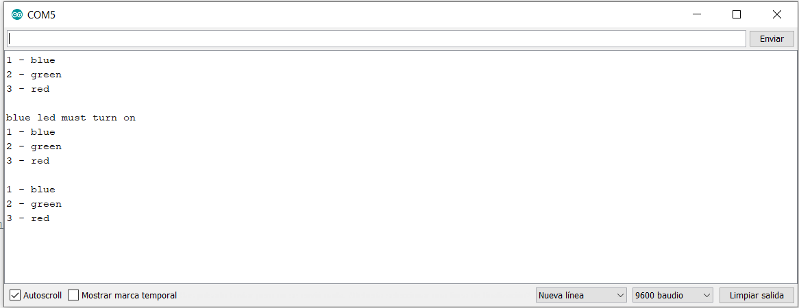
As a middle step before the Processing interface, I used the Arduino Serial Monitor to make a very simple interface. The idea is that the board receives a number through serial, evaluates the number and returns a message according to it. After typing a number and press enter, the board returns a message.
Then to control the RGB module through serial, back in the Arduino code I modified and mixed the first code (blink example) with the second one (serial monitor interface). This includes a case-switch structure. Case-switch allows to evaluate a variable and perform an action based on the value given. For example, the code can be defined so that it evaluates a variable with three possible values (one for each color of the RGB led). The result is this:
case 1: // the user chose 1
Serial.println("blue led must turn on");
digitalWrite(b, HIGH); // pin b will be connected to the blue line
delay(1000);
digitalWrite(b, LOW);
delay(1000);
break;
To improve the Arduino Code, it is useful to create sub-routines or functions, some parts of the code which are similar can be converted to functions that can just be called for into the code, so I created three functions: blue(), green() and red(). This also helps to make code look cleaner. Here is the code:
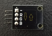
These steps let me detected that it was a hardware mistake with the sensor, the order of the pins instead of been RGB was GRB, so I modified it at the code to make it work well.
Processing
Processing is an IDE and code library developed for interactive art and visual projects. It uses a simplified java language, and allows to compile and execute code through the GUI. Processing is the precursor to Arduino IDE.
When coding with Processing, along with logic instructions, graphical elements can be defined. For this assignment, this graphical elements were used to create the interface for the RGB circuit.

I already have and Arduino code on the board designed to receive a number (1, 2 or 3), evaluate it and turn on an LED according to the value of the variable. So, the processing code will send a number over serial according to the button pressed by the user.
The processing code starts by importing the Serial communication library. Then a Serial object is created (myPort).
// Fabacademy 2020 || St. Jude FabLab
import processing.serial.*; // import the Serial communication library
Serial myPort; // This is the serial port you will use for communication
After that, I created parameters and variables for the color, position and size of each rectangle that will work as button.
// rectangle 1 parameters and variables
int rect1X, rect1Y; // XY position of rectangular button 1
int rect1Size; // Size of rectangle 1
color rect1Color; // Rectangle color variable
Then on the setup() routine I start by printing a list of available serial ports so I can find which index corresponds to the por I need for serial communication. Because the port I need is first in the list, I set the port to Serial.list()[0].
printArray(Serial.list()); // print the list of serial ports available
myPort = new Serial(this, Serial.list()[0], 9600); //create the port according to the list
Then, set the window size and background color.
size(700,300); // window size
background(255,255,255); // window background color (white)
And the parameter definition of each button.
// button 1 definition
rect1Color = color(0,0,255); //fill color for button1 (r,g,b)
rect1X = 100; // position X for button 1
rect1Y = 100; // position Y for button 1
rect1Size = 100; // side size for button 1
After that, the actual graphical interface is implemented with the draw() routine by creating each recatangle and displaying it in the window.
stroke(0,0,0); // color for button 1 edge (black)
fill(rect1Color); // color for button 1 fill (blue)
rect(rect1X, rect1Y, rect1Size, rect1Size); // command for drawing button 1
And finally, the interaction part of the code is activated when the mouse click is released. If it is released within the coordinates of each button, the code will assume the user clicked on that button and send a serial message accordingly. This is defined inside the mouseReleased() routine.
// when the mouse button is released, we ask if the position of the mouse pointer was inside the rectangle1 boundaries
if (mouseX >= rect1X && mouseX <= rect1X + rect1Size
&& mouseY >= rect1Y && mouseY <= rect1Y + rect1Size)

  {
     // if the mouse pointer was inside the button 1 coordinates this is executed
     println("turn on blue led"); //print on Processing console
     myPort.write("1"); // send 1 over serial
  }
I needed to debug the code a couple of times but it was because of mistakes on variable declarations or syntax errors. Here is the example of the code working: