Week 15
Goals of the week
Group assignment
you can find the group documentation here
- design a machine that includes mechanism+actuation+automation
- build the mechanical parts and operate it manually
- document the group project and your individual contribution
- actuate and automate your machine
- document the group project and your individual contribution
My contribution
For this week we decided to make a machine to sanitize the hands without touching any buttons. We decided to insert two direct current motors (DC motor) that move a gear capable of pressing on a spray containing sanitizing gel. My job is to think about the design of the machine.
First I created the box with a circle to allow users to insert their hands. Actually, this wasn't a good idea because I miscalculated the measurements. For this reason I decided to start from the base on which to insert a sort of tube (with holes on the sides at the sprays) where users can insert their hands without getting in any way in contact with the engine, gears and various electrical components.
That's the first result.
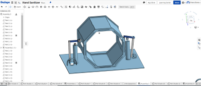
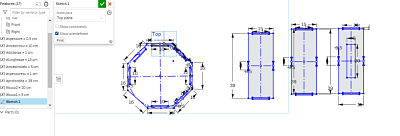
I created a sort of tunnel starting from the octagon in which I made holes in order to fit "walls", two of which have a hole in them so that the spray of the sanitizing spray can reach the user's hand. Later I created a mate fastened between this and the base on which the other elements will also rest.
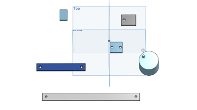
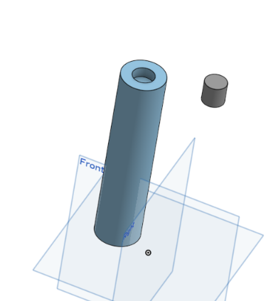
The most interesting part for me was discovering the functions of the other mate I had never used. The Revolute mate in which The first Mate connector selected serves as the rotational point and the second Mate connector selected serves as the stationary point and the Slider mate that allows movements along the axis of the z. I used the first one for the gears and the second one for my spray. To make the gears I simply built a tube with a protruding tube to represent the DC motor and many different sized splints with holes for the screws. For the spray instead I made two tubes: one for the bottle and the other, little one, for button.
Before going any further, though, I wanted to laser-cut the gear parts. So I exported the various files in .dxf format and put them on Ikscape. Unfortunately, however, this program tends to vary (even if by a few mm) the measurements of my drawings. So I decided to create the file using the computer in the lab that Illustraor has.
Illustrator
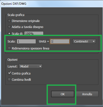
Personally I prefer to use cm as a unit of measurement, but I must admit that generally programs have millimeters set among the preferences. Even if I change these settings, I can't get an accurate conversion with Iskape. With Illustrator, however, I was able to select the scale.
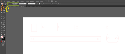
Once imported all the files, I have selected them and set the thickness of the track to 0.001 mm, selected red as the color of the track by pressing (with the elements still selected) shift and the arrow to the right of the square with the colors of the track: in this way will appear the grid rgb where you can enter the exact values (it may happen that you have other options by default, in this case just press the small icon that appears at the top right and select RGB). For the fill color of the track you must choose the null option.
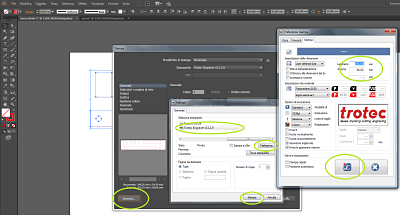
To send the file to the Job Control (Roland's software) I instead pressed on File-Print-Set-Selected Roland-Preferences-increased the measurements by one mm each and finally pressed the Job Control button.
Once the file arrived on Job Control, I simply opened this program, dragged the file into the worksheet, took the coordinates directly from the laser cutter and transported the file at the + indicating the origin.
Updates
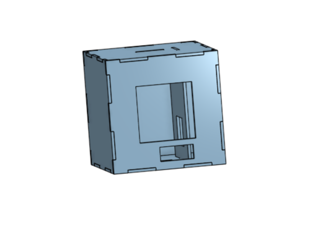
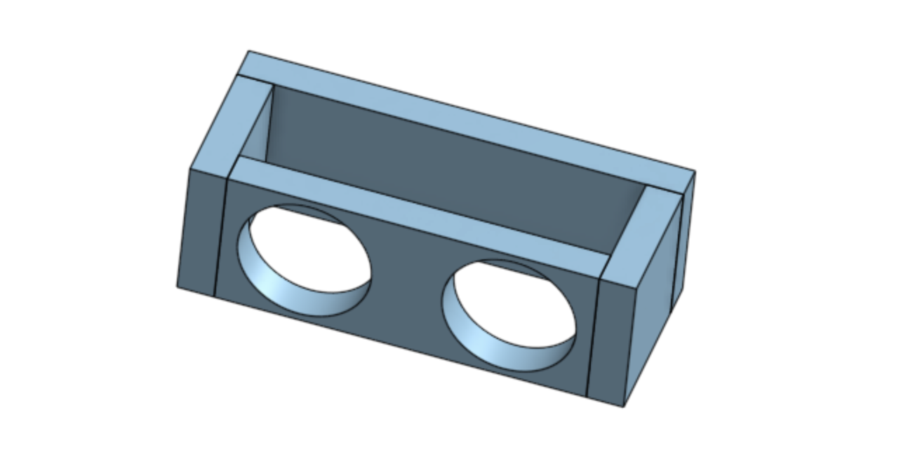
The machine I designed was too big, and our tutor suggested to me to design another one, maybe only for one hand. A simple box, much smaller, with a separator so that the hand does not touch the spray and the motor.
Furthermore initially we had thought of a mechanism able to transform the rotary force into linear force, but after some tests and difficulties our tutor advised us another system: we watched
this video
I then created a support to wrap the smaller tube of the motor (fixing it with a screw) to which I joined a sort of oval. Double various tests in which I changed the size and slightly the shape, I found the one that allowed dc Motor to bang on the spray and then let out the sanitizing gel
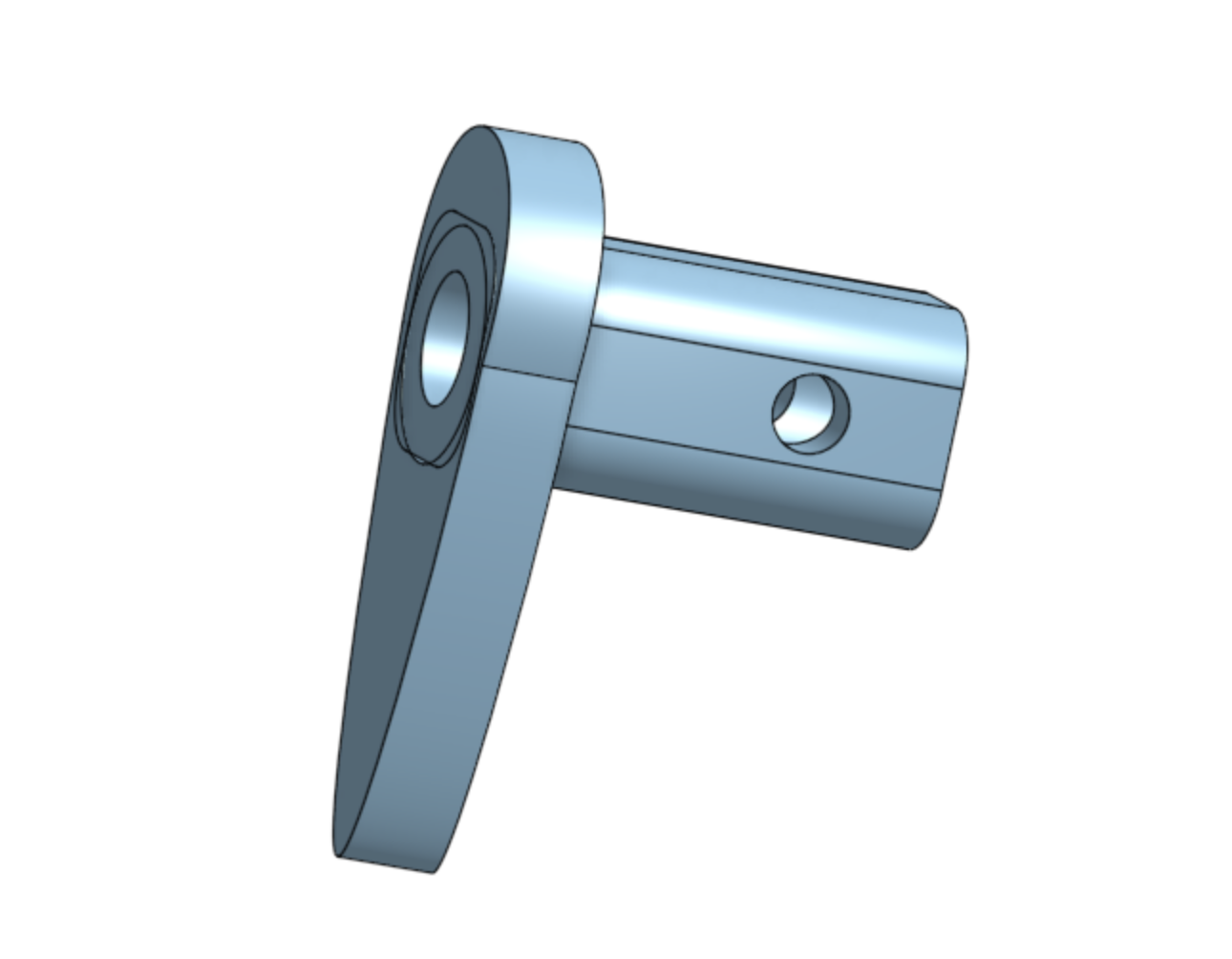
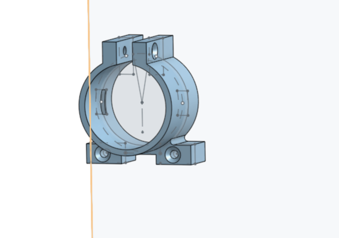
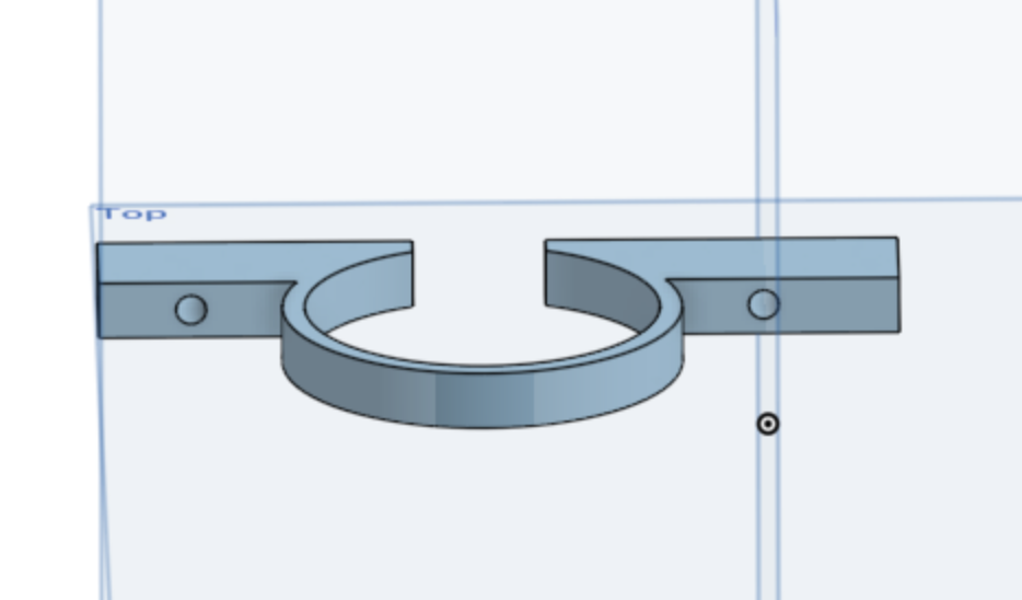
To fix the motor I created a support that wrapped it for most of its thickness, two "wings" in which I made holes for the screws and two to tighten further with a screw. To hold the spray bottle well I created two 3D printed belts to fix it to the separator. For safety we also glued the spray to the plywood and fixed it all with two Brackets. The engine is really very powerful!
I also created a small sonar case so that I can attach it to the machine. Once assembled the box we did some tests: at the beginning it didn't work, we had to move the spray slightly and make sure that everything in the machine was stable and resistant to the force of the engine. In the end, luckily it worked!
You can find assembly and operation developments here
You can find the downloadable files here
Box stlAssembly stl
Assembly sonar
File Illustrator
support stl
second support stl
third support