Week 8
Goals of the week
Individual assignment:
read a microcontroller data sheet,
program your board to do something,
with as many different programming languages
and programming environments as possible.
Group assignment:
compare the performance and development workflows
for other architectures
In order to carry out the assignments I read the microcontroller datasheet and a very interesting book called Make AVR programming.
The first one is essential, but I strongly suggest also the last one, it tourned out absolutely helpful.
What Is a Microcontroller?
"Microcontrollers are often defined as being complete computers on a single chip,
and this is certainly true."
In my opinion what a this small component can do is incredible, but it happens only if you program it with a programming language as C, Phyton or Java (to name a few).
Toolchain
The first chapter of Make AVR programming is helpful to understand how a microcontroller works, but programming instructions star in chapter 2.
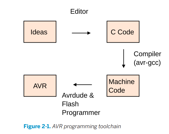
A really important concept to bear in mind is the toolchain:" a long and winding road from the code you type into your editor to a chip on
your desk that turns a light on and off."
More specifically I am going to:
-Write the source code in a editor (I use Brackets);
-Turn this source code into a machine code through a compiler like Avr Gcc;
-Use an uploader software like Averdude and a hardware flash programmer to send the machine code to the Avr chip (stores the instructions in its nonvolatile flash memory).
Here you can find a very explanatory image taken from page 15 Make AVR programming.
C code
The first step is wrtiting the code in an editor.
I found helpful these tutorials:
- The C processor;
- Tutorial, write your first Avr C programming-Blinking led;
- Make Avr programming (again)
This is my code
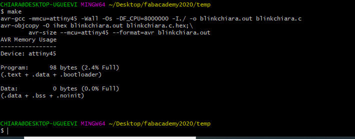
Makefile
Before starting I read how to creare a Makefile. It is really important cause they allow you not to write always the same commands in your code, but to memorize them in the makefile and insert them in the code.
This
is a truly helpful guide to understand the process, but fortunately I already had the makefile that professor Neil created for us. I only eliminated all the parts that are not necessary for this task.
This is my makefile
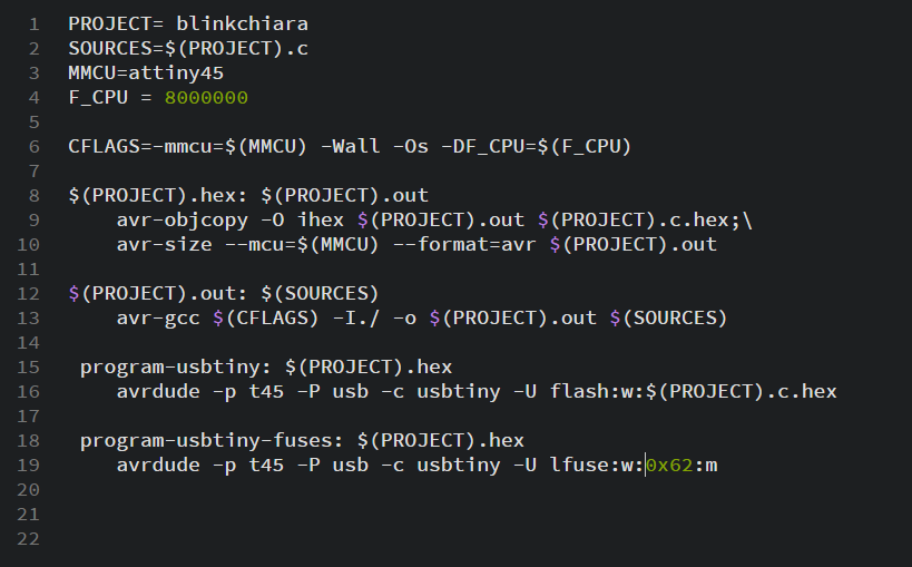
Regarding Makefile
Variables
Near Project there is the name of my C code, "Project" is the term with which I will refer to my file named "blinkchiara.c", to indicate the source dunquenon is more necessary to write this name (the second line is proof of this).
In the third line, near MMCUI specified the type of AVR chip I am using.
In F_CPU I indicated
the compiler what clock speed my chip will run at, not having the external clock source it is 8 Mhz.
In CFLAG there is the processor target, -Wall is used to set up all the warnings that can be given
Commands
For better understand the first command (line 9), is important to read the second one (line 12), indeed C code had to be an output before be converted in a .hex file (hexadecimal).
Then, .hex file must be moved from the (big) computer memory to the flash memory of the programmee using both an hardware programmer(Fab ISP) and a software programmer (Avr Dude). More specifically, flash is where I would like to do something, :w is What I would like to do (in this case writing, but could be also r that means read) and the remaining wording is the object I would like to write, in this case my .hex file.
To conclude, the last command is used to indicate the fuse value, l before "fuse" means "low" and :m means that the value that had to be written is already there.
Fuses
Fuses are 3 bytes of memory that are used to modify the general behavior of the microcontroller.
In order to calculate it I used this calculator and for better understand them I read the datasheet (pages 149 and 31 in particular).
The calculator is very easy, I only selected AtTiny45 and it gave me all the values.
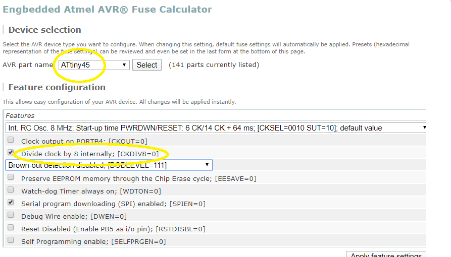
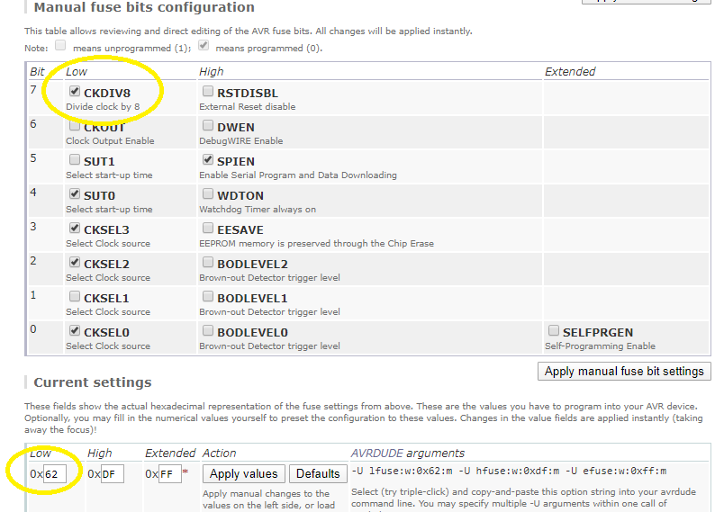
Note that fuses are
read as logical zero, “0”, when programmed. There are Fuse Extended Byte, Fuse High Byte, Fuse Low Byte. The latter two are more used than the first. In this case I used only Fuses Low Byte.
Tab 20.5 of datesheet is very explicative
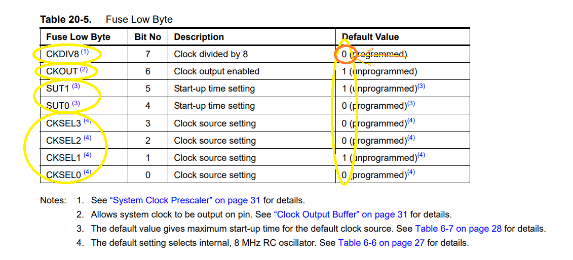
In the first column there are the hardware logs:
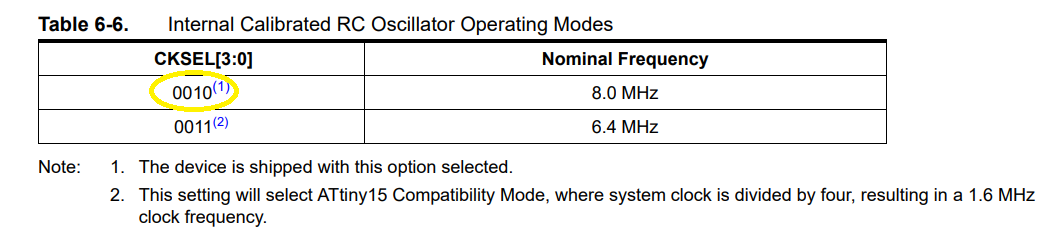
- CKSEL are better described on page 27 of the datasheet: "By default, the Internal RC Oscillator provides an approximate 8.0 MHz clock. Though voltage and temperature
dependent, this clock can be very accurately calibrated by the user...This clock may be selected as the system clock by programming the CKSEL Fuses as shown in Table 6-6 on page
27. If selected, it will operate with no external components."
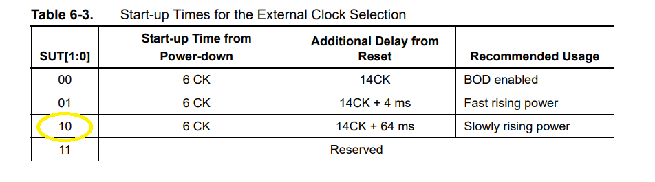
- SUT is used to indicate the time when the crystal/resonator must be activated. It is better described on page 26 of the datasheet, in the table 6.3 in particular.
- CKOUT is the clock output enabled. If I program it, the clock that is read by the microcontroller is copied into some particular pin. That's if I want to know if something's wrong. I left it unprogrammed (1).
- CKDIV8 divides the clock by 8. Contrary to table 20.5, I decided to leave it unprogrammed (1).
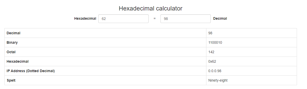
So the final sequence, as indicated in the table, is 11100010
This sequence is nothing more than the 0x62 (hexadecimal value) that the calculator above mentioned provided us in a few seconds
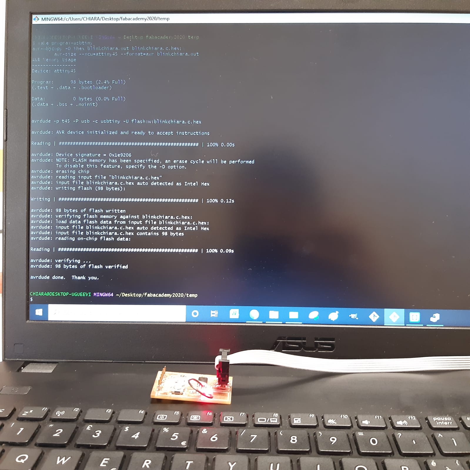
Git Bash
Once I compiled the .C file and created the .hex file, with the command "make program-usbtiny" I used averdude and a hardware programmer to write the .hex file in the flash memory of the hello board.
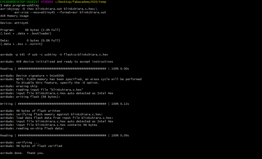
This is the result