Week 11
Goals of the week
Individual assignment:
add an output device to a microcontroller board you've designed,
and program it to do something
Group assignment:
measure the power consumption of an output device
Buzzer
We still are in lockdown, so it's not possible for us to mill and well a board. For this reason I used Arduino and the components that my tutor sent to me. This is the result:
I connected the Arduino to my computer using an USB cable and the Arduino to the buzzer with a jumper that I started from port D6.
This is the code:
It emits a tone for 1s (1000 m/s) when I pull the button, otherwiseit remains silent
LCD
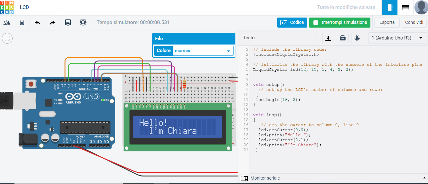
Something wrong happened with "my" jumpers, so I didn't manage to properly connect my Arduino with the LCD sensor. For this reason I used a free online collection of software tools that help people all over the world think, create and make: Tinkercad. By pressing the "circuits" button and then "Create a new one", I first inserted the components I needed: the Arduino, the BreadBoard, a resistor and the LCD. I then made the connections between them, but this time it was more difficult. That's why I followed this very interesting tutorial which helped me figure out how to connect the LCD to the Arduino ( interfaces pins are 12, 11, 5, 4, 3, 2).
This is the code:
And this is the result
Servo Motor
"A servomotor is a rotary actuator or linear actuator that allows for precise control of angular or linear position, velocity and acceleration.[1] It consists of a suitable motor coupled to a sensor for position feedback. It also requires a relatively sophisticated controller, often a dedicated module designed specifically for use with servomotors".
Since I didn't have the servomotor at home, I decided to use Tinkercad again. I used this tutorial in order to create a circuit that would allow the servomotor to rotate 180 degrees and then stop and then rotate 180 degrees back (in the direction it began).
Components Needed
-Servo Motor
-Arduino
-3 pin male to male header
Pin 9, Ground pin and 5V pin must be connected to the servomotor.
This is the code:
This is the result:
Led RGB
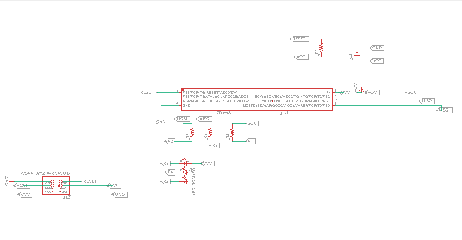
Now that we could go back to the lab, I decided to use the rgb led as output also because it will be an output of my final project board. First of all I studied the board that Professor Neil published and I made some slight changes. The rgb led has one common anode, one cathode for blue, one for red and one for green. Each cathode is connected to a resistor (1k for red and green and 500 ohm for blue). The resistors are then connected one with the MISO pin, one with the MOSI pin and one with the SCK pin. Finally the anode is connected to VCC.
This is the schematic
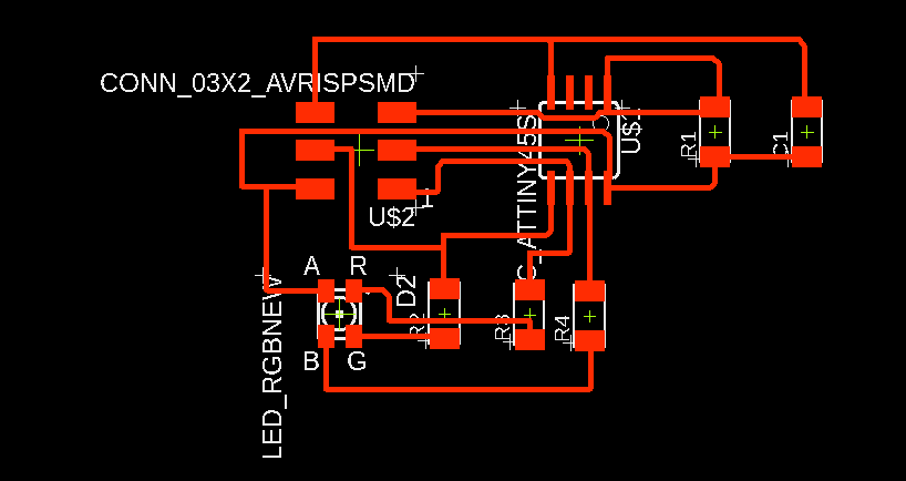
This is the board
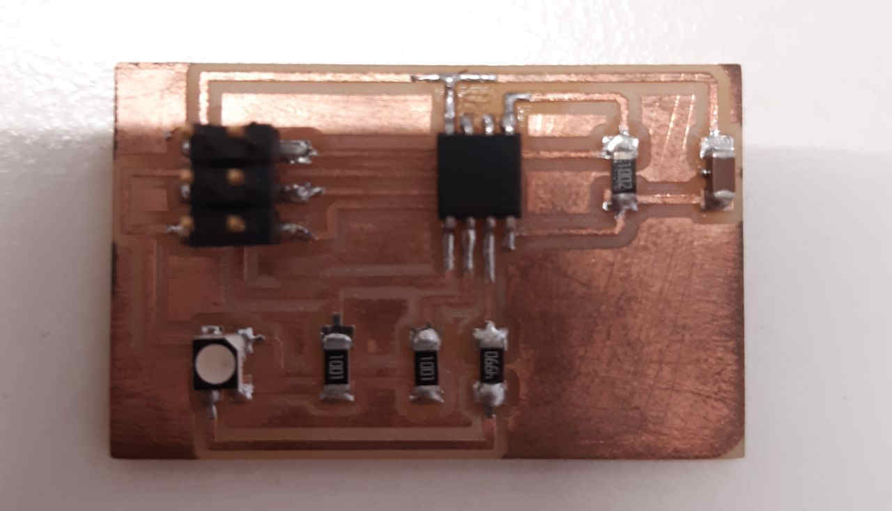
This is the milled and soldered board
Finally I used this code
This is the result