Week 2
February 6th
Today we started using 2D and 3D modeling programs.
First this morning I started using Inkscape (the free version of Illustrator).
This is the link to download it. I'd never used it before and, although it's quite intuitive, I preferred to take a look at this tutorial .
Inkskape is a vector graphics software, which is the kind of graphics that gives more weight and quality to lines rather than colors. This last aspect is taken care of by raster graphics . Today I started using two programs: My Paint and Gimp .
I used My paint when I was a kid, just for fun. I had used Gimp a few years ago but I didn't remember much, so I followed this tutorial .
Regarding 3D modeling, I downloaded several programs and tried to figure out which one was the most suitable to realize my project and which one I could be better with.
First of all I registered with an educational account at the site of Onshape , later I registered to the site of Solidworks through the invitation received by e-mail. Finally, I registered with an educational account at the Fusion 360 site .
February 7th
If yesterday I spent my whole day looking at a lot of programs, today I tried to use and summarize them better.
February 10th
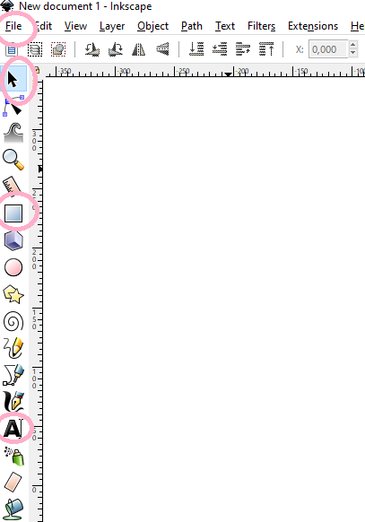
After several attempts that didn't beat me, I decided to model phalanx by phalanx following the measurements of the sketch above. For convenience I worked on different Part Studio. In the case of phalanges of equal size I created them only once (for this reason they are named with letters and not with the name of the phalanx or finger). As far as the first phalanges are concerned, I simply created rectangles using the "rectangle corner" tool (top left) and giving the correct dimensions by selecting the "dimension" tool on the top right, clicking on the line I wanted to resize and inserting in mm the size I wanted.
As for the final phalanges, instead, I used this link to learn how to create light curves. I selected the "3 point arc" tool at the top left, clicked on my starting and ending punyo and made the arc to be at the top. I wanted the curvature to be the same for all the final phalanges, so I calculated the ortagonal dimension by clicking on the "dimension" tool, the point of origin and the point from which my bow started (the end of the left vertical line). I selected the 60 mm size because it is the one with which I obtained the curvature I liked the most.
Creating the palm was a bit more complicated: the vertical line on the left is the one that will join with the little finger, the horizontal line is the one that will join with the wrist and the diagonal line is the extension from which I will then (in the 200 mm recess) join my thumb.
I then extruded the various parts giving a depth of 175 mm to the first phalanges and one of 150 mm to all the others.
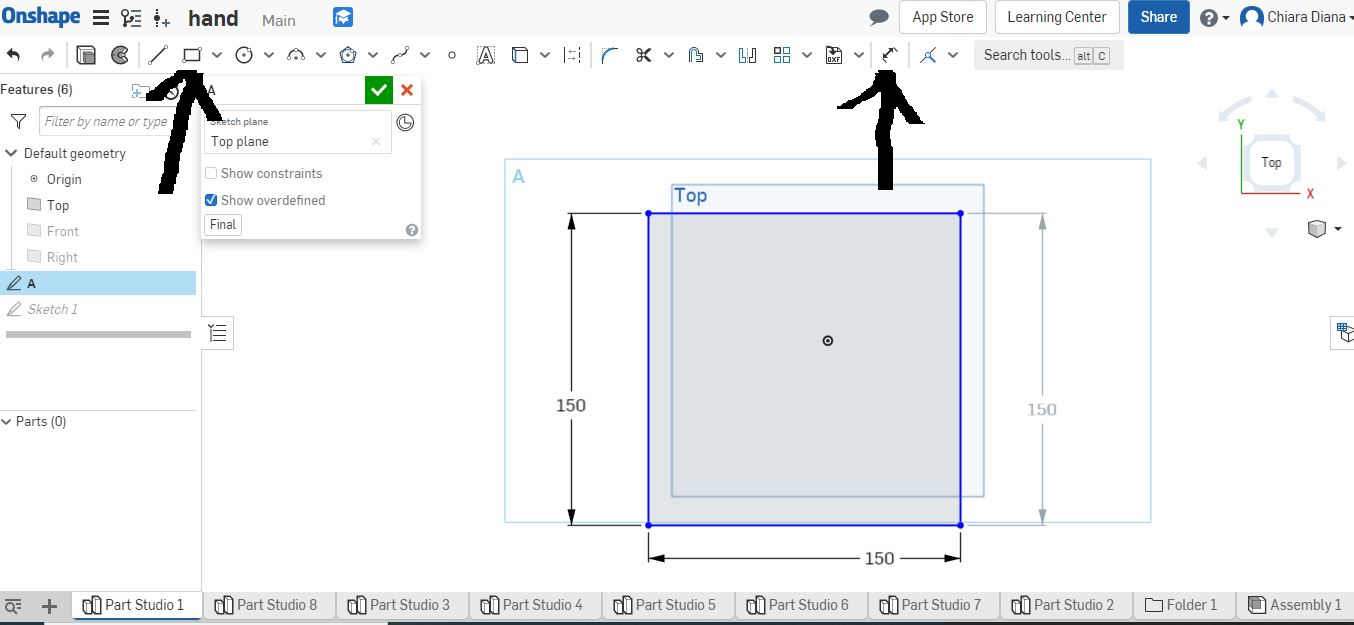
("corner rectangle" and "dimension" tools)
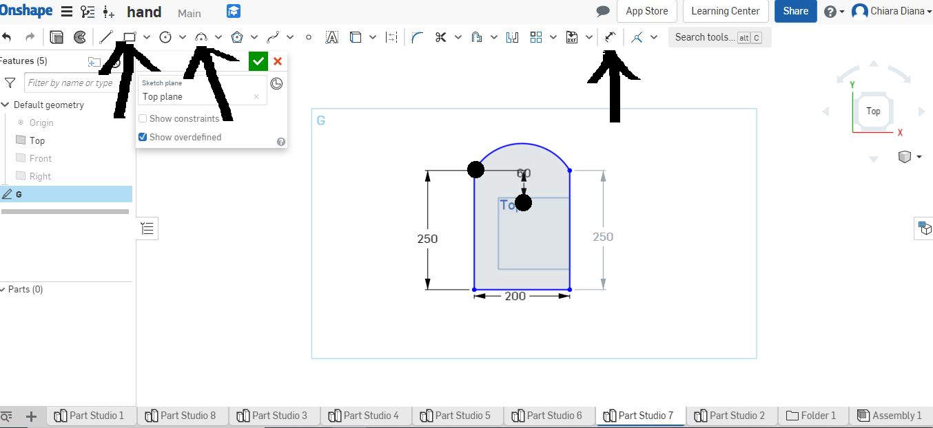
("corner rectangle", "3 point arc" and "dimension" tools)
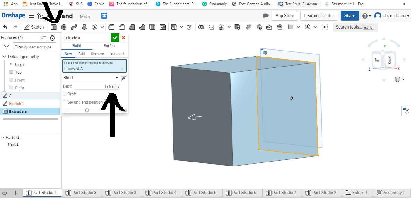
("extrude" tool)
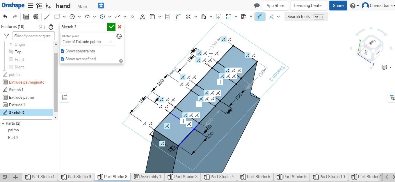
Once I had extruded all the pieces of my hand, I tried to assemble them, but as I hadn't inserted the right "support surface" for the fingers, the system couldn't fit them in the way I had imagined. So I created a sort of "table" with the spaces in which to insert the phalanges, also considering the spaces between the fingers. Tomorrow I will try to assemble everything.
Some considerations regarding OnShape
After using various 3D modeling software I came to the conclusion that OnShape is my favorite free software (with student license). What I like the most is that by pointing the mouse on the tools a detailed description of it appears. It is also possible to work on different part studio (levels) and in the Assembly you can choose the elements to merge and at which point.
Updates
In the second week I spent all my time trying to get familiar with OnShape software and neglected the 2D graphics part. Now I've decided which will be my Final Project (different from the one I thought at the beginning). So it's time to finish what I left pending!
You can find more information regarding the final project here but synthetically:
I would like to build a plane in which the patient can rest his foot and put there at least 2 pressure sensors (one in the toe and one in the heel) so as to detect the weight distribution shown both in the interface and in a 3d model of a foot.
Inkscape
Wooden base
The base that I would like to create should have a rectangle where, thanks to the image of two footprints, people can put their feet in the right place (the one where there will be sensors to detect the weight distribution). In the first rectangle the user will place both feet, but it would be nice to create at least two to check the weight distribution even during a walk.
For this reason I made three rectangles using the Create rectangles and squares tool (f4) , so I enlarged them using the Select and transform objects tool (f1) . Subsequently I imported the vectorial images of the impressions simply by doing File - Import and, again using the Select and transform objects (f1) tool, I could enlarge them and position them as I wanted. I then inserted the text using the Create and edit text objects tool (f8) .
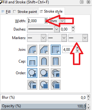
I also inserted some arrows using the Bezier curves and straight lines tool (shift f6) and then selecting the tip from the third pane of the Markers in the Stroke Strike window. I suggest this tutorial.
This is the result

After that, I decided to try to do something a little more creative/difficult: try drawing the stylized prints myself. It proved more difficult than expected and I admit that the result is not perfect. Anyway, I drew lines with the Draw Bezier curves and straight lines (shift f6) tool by clicking on the mouse every time I wanted to create a node and double-clicking to release. Between the two nodes a segment is created that can be curved thanks to the Edit paths by nodes tool and the thickness from the line can be set by changing the width data in the Stroke Style window (I suggest this tutorial).
Some considerations regarding Inkscape
I think Inkscape is a great software to create primitives such as square rectangles, star circles etc. with ease. But it's not only possible to create vector images or vectorize bitmpad/raster images as done in week 3, you can also do more difficult operations like creating intersections, divisions and extrusions. I really appreciated the interface that I think is simple and intuitive. The only flaw, but probably due to my unfamiliarity with the program, is that it's really difficult to create shapes from scratch with precision.
Gimp
Interface aspect
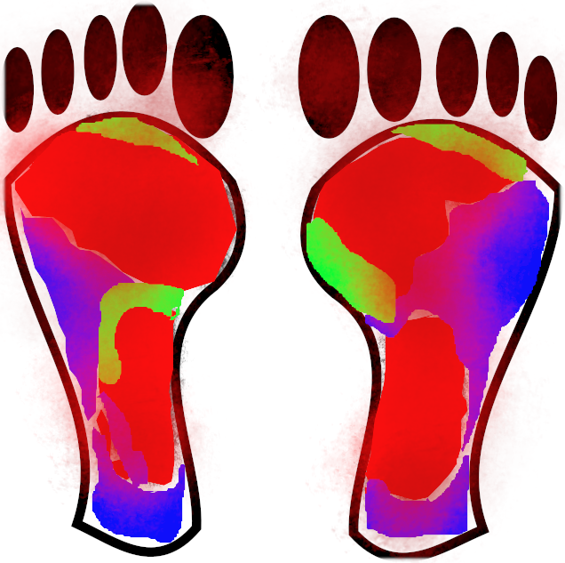
The interface shall provide weight distribution data by means of colours: red to indicate the point where there is more weight, blue to indicate the parts of the foot where there is less weight and green to indicate the parts where there is neither too much weight nor too little.
After creating the vector image of the footprint with InkScape, I opened the image on Gimp by simply clicking on File, Open and selecting the image.
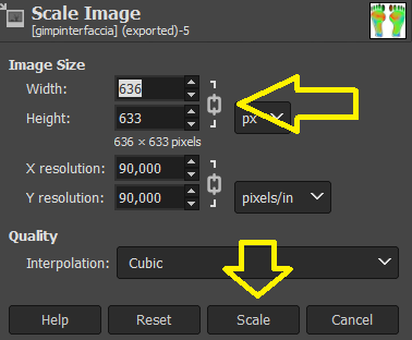
I enlarged it by selecting Image , Scale Image and changing the height dimensions by keeping the padlock between height and width closed so that the width dimensions were increased directly from Gimp in a proportional way.
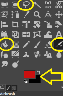
Next, using the Fuzzy tool I selected some areas that I colored using the Bucket Fill tool , changing the color by selecting the white or black square and then from the window that opens. To blur the contours I used instead the Fuzzy Border tool, in this regard I would like to point out this tutorial that suggested to follow this process: Filters → Decor → Fuzzy Border .
This is the result
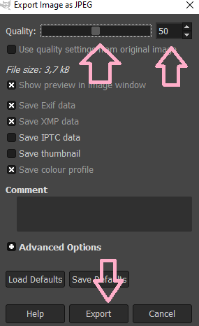
Finally with Gimp you can compress images by simply clicking on File -Export, you need to specify the jpg extension and then move the quality slider (or enter the compression number by hand), so click on Export.
Some considerations regarding Gimp
Gimp is definitely better suited to editing photos than creating them. I know that many people don't appreciate its usability and actually you need to get a little familiar with it before using it with ease. Personally, what I like most about this software is that you can work on different levels and gradually obscure the ones you don't want to make changes to.
Paint
I use Paint to highlight the elements/tools I name in the documentation so that they are easily identifiable. It is useful to quickly resize images and add elements such as arrows or circles, but also to highlight some parts with different colors and add text
Some considerations regarding Paint
Surely it is the simplest and fastest software, but at the same time it is limited to very few functions.
Some considerations regarding Fusion 360, SolidWorks, Cinema 4D and Free Cad
Doing a little research, I could see that with Solidworks and Autodesk, projects have been developed that are generally more complex than what I saw in relation to OnShape. However, the interface of these tools seemed to me very unintuitive and this made my attempts frustrating. The 3D modeling software that fascinated me the most is instead Cinema 4D which is a professional and paid software that has only a free trial version. I also tried to use Free Cad and it seemed quite simple, but maybe limited.