Week 9
Goals of the week
Because of the Corona Virus I won't be able to go to the lab this week either and then mill and solder the cards. I have therefore been allowed to use Arduino to read a board to which I will add digital and analog sensors. (Sensors and Arduino kit have been kindly sent to me by my tutor)
Arduino
First of all I read this helpful material:
- Pull up resistor
- What is an Arduino?
- Installing Arduino Ide
- Arduino Reference
Button sensor
Once I installed Arduino, I used this really helpulful link where I found, not only the code, but also an explanation about the component, its features, specification, platforms supported, a funny way to use this sensor (a wooden laser gun), and most of all, how to use the sensor.
Code in Arduino
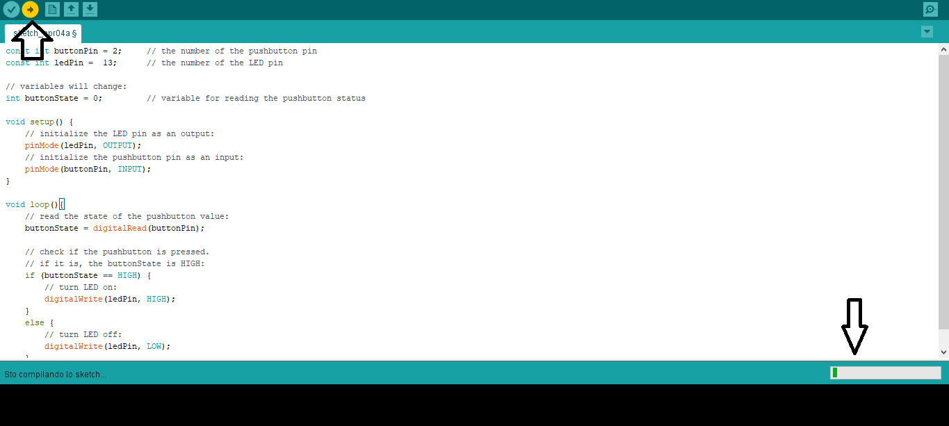
First of all from "Tools" I chose the board corresponding to mine, that is "Arduino one". I copied the code in the Arduino sketch, then I pressed the first button in the top left to verify that the code was right.
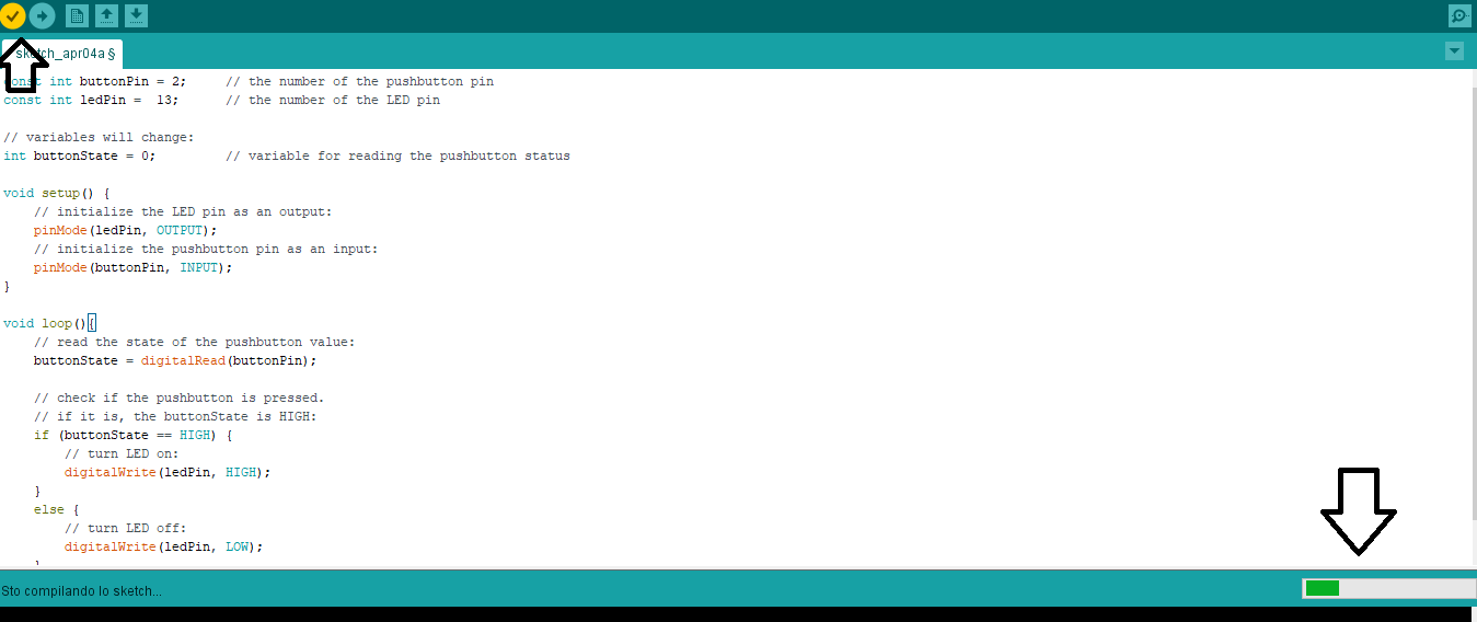
After few seconds I clicked on the second button in the top left in order to upload it
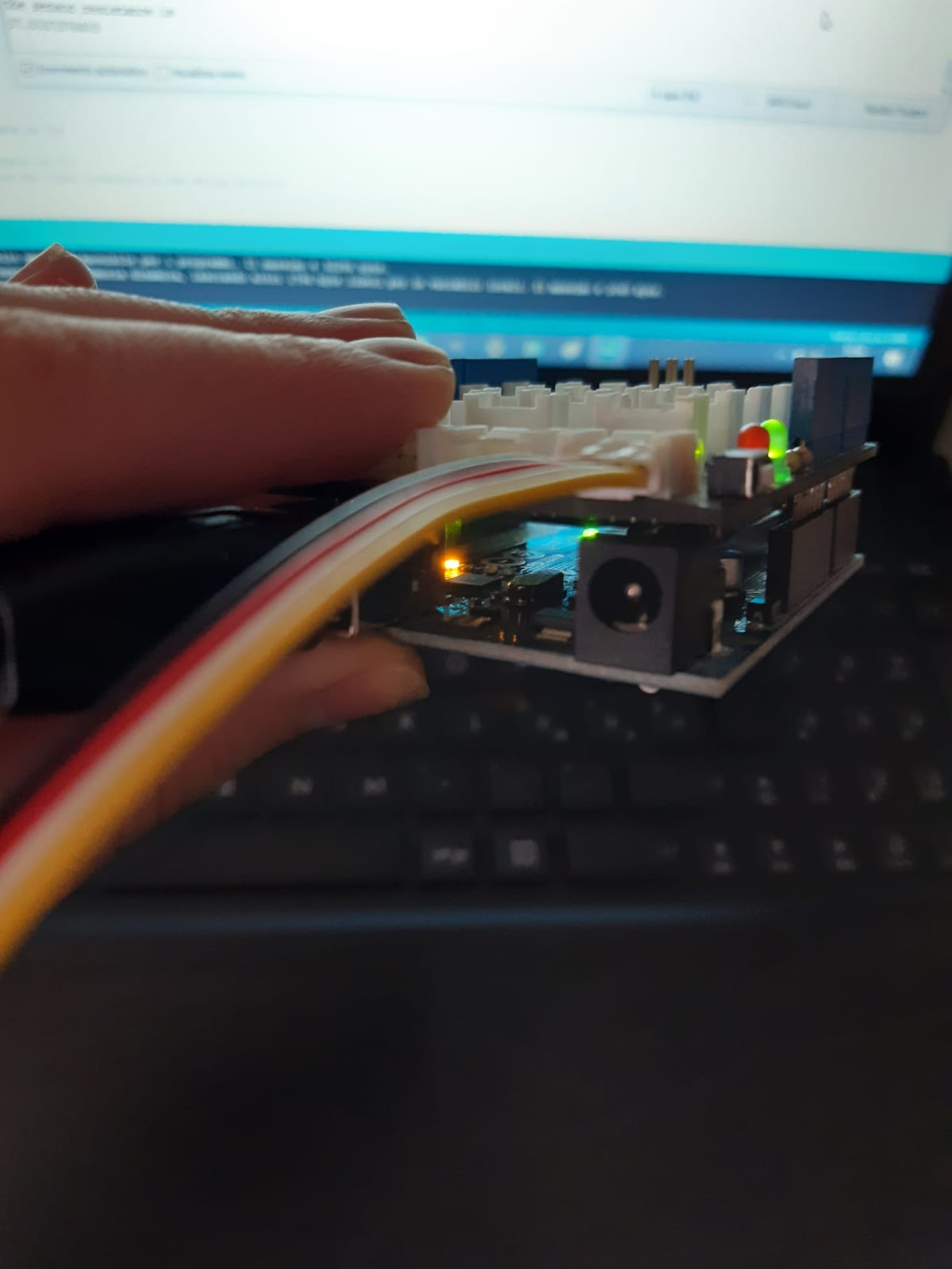
Meantime I connected the Arduino to my computer with a USB cable and the button sensor with a cable in port D2 (button is a digital sensor) and here the result.
Touch Sensor
I used the same site to get more information about the sensor and get its code. Again, I chose the board corresponding to mine (clicking on "tool" and "board"), that is "Arduino one". I copied the code in the Arduino sketch, then I pressed the first button in the top left to verify that the code was right and I clicked on the second button in the top left in order to upload it.
This time I had to connect the Arduino both with the Touch sensor and a Led Socket (connected whit a led).
Here the result.

Light sensor
To activate the light sensor, I took the code from this site. Again, I chose the board corresponding to mine (clicking on "tool" and "board"), that is "Arduino one". I copied the code in the Arduino sketch, then I pressed the first button in the top left to verify that the code was right and I clicked on the second button in the top left in order to upload it. This time I also clicked on the "serial monitor" in the top right in order to read the changes for example when I turned the camera light on or off or when I covered the sensor with my finger (adding or subtracting light). Regarding the hardware, due to the fact that the light sensor is an analogic one, obviously I connected it to the analogic port of my Arduino.

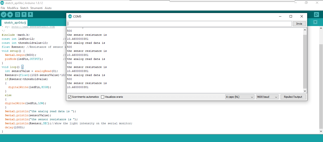
Here the result.
Temperature sensor
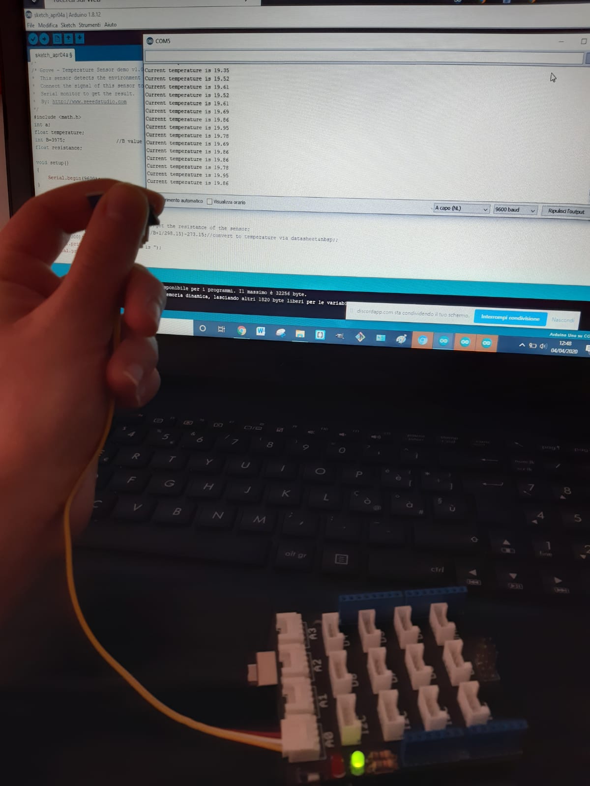
Finally, taking the code from here I could measure the temperature of the house! Again, I chose the board corresponding to mine (clicking on "tool" and "board"), that is "Arduino one". I copied the code in the Arduino sketch, then I pressed the first button in the top left to verify that the code was right and I clicked on the second button in the top left in order to upload it. Also this time I clicked on the "serial monitor" in the top right in order to read the changes.
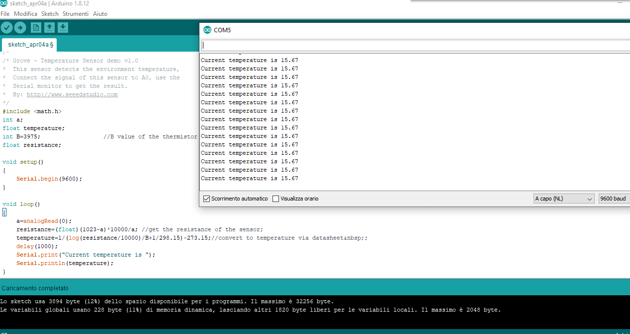
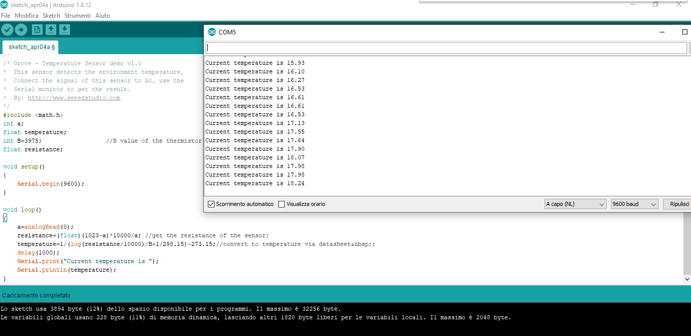
Even in this case, due to the fact that the temperature sensor is another analogic one, I connected it in the analogic port
Board with thermistor
I created a board on Eagle following the example that professor Neil had uploaded in the schedule regarding this thermistor. I only added a link between Tx (FTDI) and PB1 of the AtTiny. Rx and Tx, in fact, are the cables for serial communication. If both are connected it is possible to have a bidirectional communication (from outside the board and vice versa).
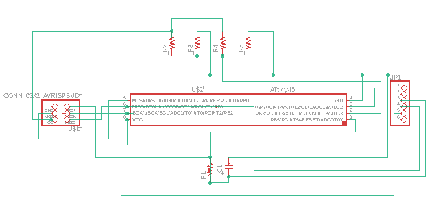
Wheatstone Bridge
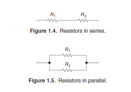
At the beginning I studied how voltage dividers work from this Sparkfun tutorial but even though it all seemed pretty clear to me, I couldn't fully understand the board. It was only after I had thought about it a lot with my classmates (also using this calculator ) and talked to our tutor, that we understood that there was a Wheatstone Bridge. To better understand how it works I recommend this tutorial. It is basically a combination of 4 resistances connected in order to give a null center value. The resistor can be arranged in series or in parallel. "By putting resistors in series, you always get a larger resistor.", "By putting resistors in parallel, you always get a smaller
resistor." (The Art of Electronics, page 6)
The Wheatstone Bridge circuit is nothing more than two simple series-parallel arrangements of resistances connected between a voltage supply terminal and ground producing zero voltage difference between the two parallel branches when balanced.
Gimp
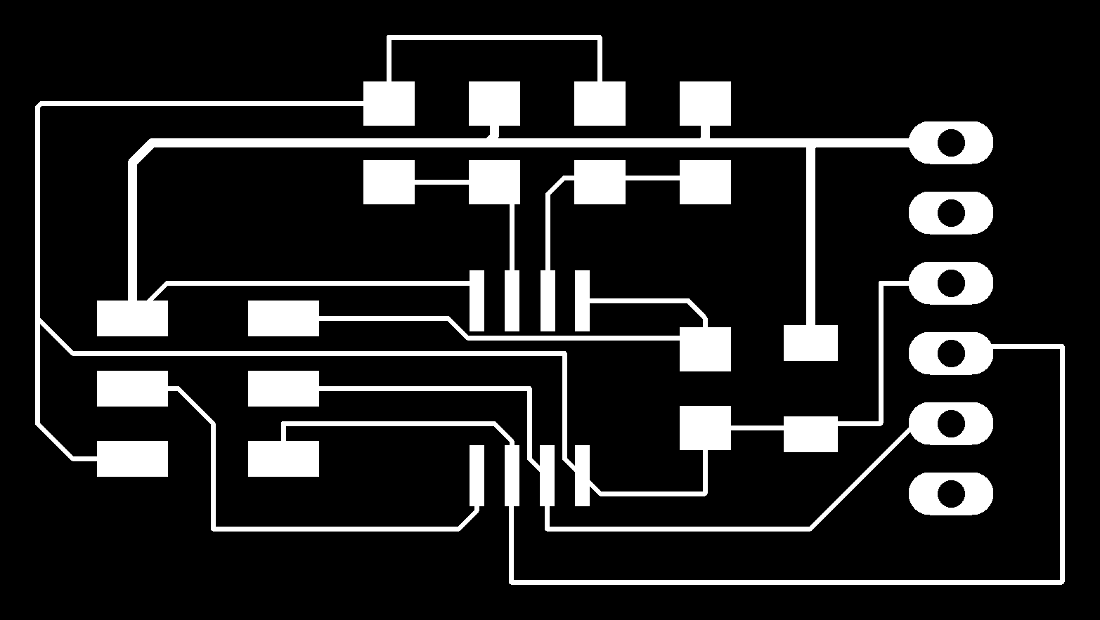
Once I exported the .png file from Eagle, I imported it on Gimp and exported the traces, outlines and holes files. (I admit I didn't exactly remember the process. That's why it was helpful for me to follow my documentation of Week 6)


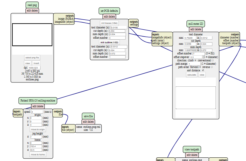
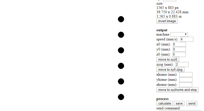
Mods
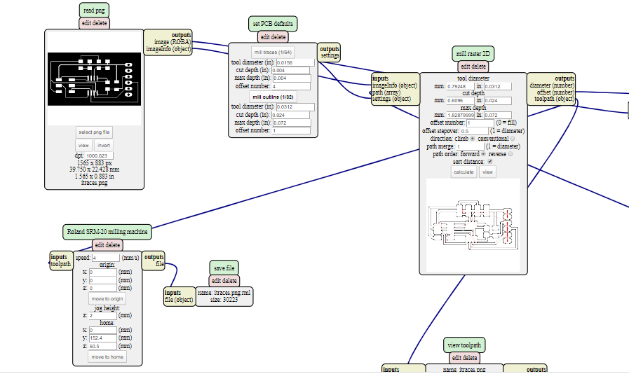
Then I converted .png files to .rtl using Mods
Update
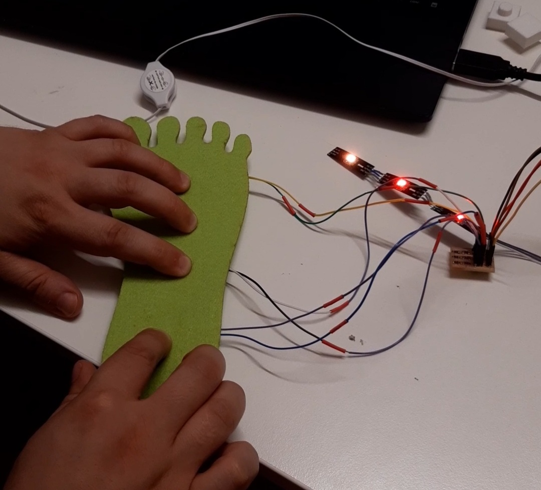
Due to quarantine, I haven't had a chance to mill and weld this board. So I thought to start doing the one I will use for my Final Project and where I will insert the FSR sensors with the resistors.
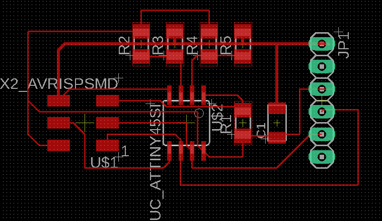
I connected it to the main board through a 5 pinheader (tx, rx, ground, vcc and fsr), I inserted 3 pinheader of 2 and to each one I connected an fsr. For each fsr I inserted two resistors: one 10k and one 5k (4.99 to be precise). The sensors will then be connected to some rgb leds present in a strip of neopixel.
You can find the eagle and gimp material in the final developement page. In order to better understand how fsr works I found really helpful
this tutorial
and
this guide
I used the Avr ISP also in this board like in week 6 and in my Final Project
This is the code
This is a demonstration with the board
You can find the downloadable files here
Board with fsr
BoardSchematic
Board with thermistor
BoardSchematic