Week 13
Goals of the week
Individual assignment: design, build, and connect wired or wireless node(s) with network or bus addressesGroup assignment: send a message between two projects
I²C Inter-Integrated Circuit
There are three protocols for two boards to communicate: Serial port, ISP and Ic2. Looking for more information about the last one, I found a very interesting tutorial
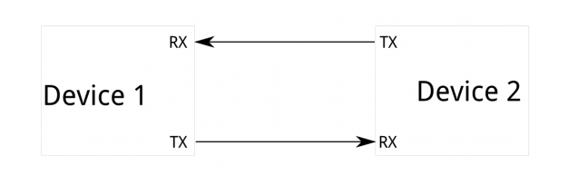
What's Wrong with Serial UART Ports?
"Because serial ports are asynchronous (no clock data is transmitted), devices using them must agree ahead of time on a data rate. The two devices must also have clocks that are close to the same rate, and will remain so--excessive differences between clock rates on either end will cause garbled data." It means that 10 bits of transmission time are required for each 8 bits of data sent. In addition, only two devices can be connected in this way.
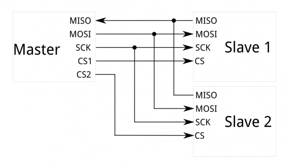
What's Wrong with SPI?
The biggest limitation of this protocol is that many connections are needed (connecting only one master to only one slave requires four lines): this can become problematic if several slaves are connected. However, the SPI method is good for full duplex connections (sending and receiving data simultaneously) at high speed and with clock frequencies above 10 MHz.
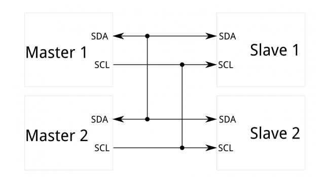
I2C
"I2C requires a mere two wires, like asynchronous serial, but those two wires can support up to 1008 slave devices. Also, unlike SPI, I2C can support a multi-master system, allowing more than one master to communicate with all devices on the bus." Two lines are used to send and receive data: SCL (address frame) and SDA (data frame). To initiate the address frame, the master device leaves SCL high and pulls SDA low. The address frame is always first in any new communication sequence. After the address frame has been sent, data can begin being transmitted. The master will simply continue generating clock pulses at a regular interval, and the data will be placed on SDA by either the master or the slave, depending on whether the R/W bit indicated a read or write operation
Master Reader/Slave Sender
Once I decided to use the i2C protocol, I looked into how this worked with the Arduino Uno that my tutor provided me at the beginning of the lockdown. I then found this tutorial
"Arduino 1, the Master, is programmed to request, and then read, 6 bytes of data sent from the uniquely addressed Slave Arduino. Once that message is received, it can then be viewed in the Arduino Software (IDE) serial monitor window."
To connect two Arduino you need to connect the A4 and A5 pins, connect the Ground and the Vcc (5V).
So I entered the codes (which I'll explain in the next paragraph) on the Arduino Ide, connected the Arduino master to the computer via USB cable and the two Arduino with the above mentioned method. Ideally it would be necessary to connect both Arduino to the computer through a USB cable (for each one), but I had only one cable. The Vcc connection is just to make up for this lack and in this regard I suggest this tutorial.
I then connected the Arduino master to the computer via USB cable and loaded the sketch from the software to the hardware. Once I disconnected the Arduino master, I did the same with the Arduino slave. So I connected the two with the cables (ground, vcc, A4 and A5) and connected the Arduino master to the pc.
Code
I decided to let the Arduino LED (connected to pin 13) light up in the slave Arduino.
Master codeSlave code
This is the result
Useful links
I2CMaster Reader/ Slave Sender
Master Writer/Slave Receiver
Wire Library
Master/Slave i2C connection