4. Computer controlled cutting
This week’s goal is to get some hands-on experience in computer numerical control (CNC) cutting. Therefore, I used a vinyl cutter and a laser cutter.
Vinyl cutting
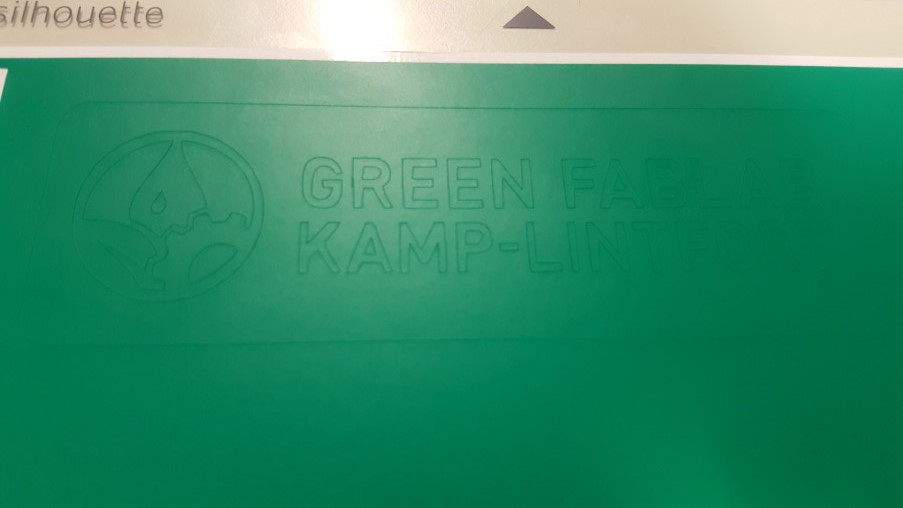
For plotting something on the vinyl cutter, I first needed a design to plot. I worked with the already excisting logo of the Green FabLab that is being set up at the moment and that I’ll be working in.

The software I worked with is Silhouette Studio 4.3. I opened the logo file in the software and used the trace function to recognize it. As trace preview I chose solid fill and then changed the parameters Threshold, Despeckle Threshold,and High Pass Filter to just detect the edges I wanted to cut. The plotter I was using is a Silhouette Portrait. I cut with on a sticker foil using the setting for sticker foil (cutting depth: 1, pressure: 14, speed 8). Since the sticker I wanted to plot has two different colors, I cut it twice from two fiferently colored sticker foils. According to the settings I chose, the plotter just cut through the sticker foil and not through the bottom layer that was sticked to the cutting mat.
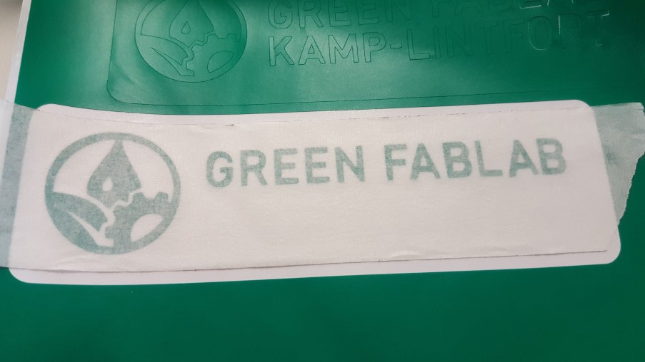
To end up with only the visible part of the sticker, I peeled off everything that was not supposed to be seen. As a transfer foil regular masking tape was used.
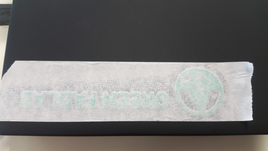
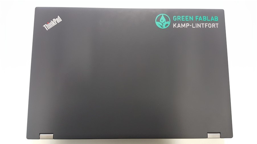
I peeled off the masking tape with the sticker sticking on it and placed it on my laptop to transfer the sticker.
After peeling off the masking tape, just the sticker was left on the surface.
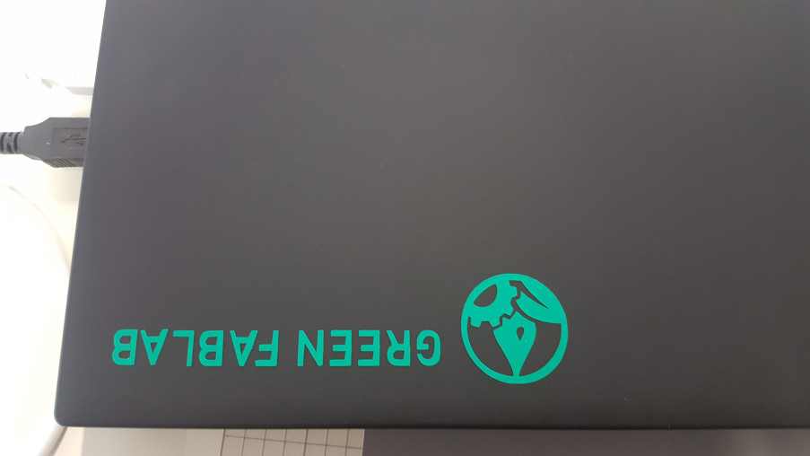
The next step was to repeat the procedure with the second color. The result can be seen on the following photo.
Lasercutting
Group assignment
Laser cutters are CNC machines that cut with a laser beam, other than a vinyl cutter that uses a blade. The laser cutter I was using is an Epilog Fusion 40, 60 W. In order to cut a parametric design with multiple parts that hold together with press fits. To design such a press fit, it is crucial to know the kerf (the width of the cut) of the laser cutter using certain settings.
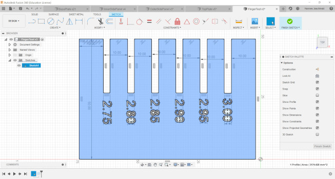
Therefore, I designed a test piece in Autodesk Fusion 360. It is a comb shaped piece with different slot widths.
I created a sketch, made a 2-point rectangle as the body outlines and several rectangles to make the slots. With the sketch dimension function I was able to define the widths of the slots. Those were 2.75, 2.8, 2.85, 2.9, 2.95 and 3 mm.
The sketch was then exported as a .dxf file and opened in Rhino. There I marked the objects I wanted to engrave and used the command “hatch” on them. Different layers, being represented by different colors, made it possible to use different options for engraving and cutting in one file.
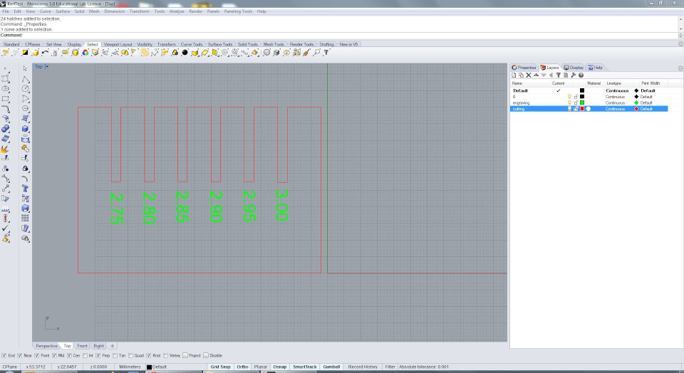
The lines to cut were defined as hairlines. In the print settings I then set up the properties for engraving and cutting, cut and then changed the values according to the previous result. For engraving I ended up with 100 % speed and 65 % power. For cutting I eventually used 8 % speed, 100 % power and a frequency of 10. A sheet of mfd, bigger than the object to cut, was placed inside the laser cutter and moved to the top left corner. Then the focus was set with the cutter’s focussing tool and the jog was set to the top left corner. With the air compressor and the gas extraction system turned on the part was cut.
After cutting I tested in which slot a 3 mm piece of mdf fitted best, resuting in a press fit.
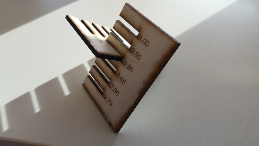
It did fit best in the 2.9 mm slot. I, therefore, assumed the kerf was 0.1 mm.
Individual assignment
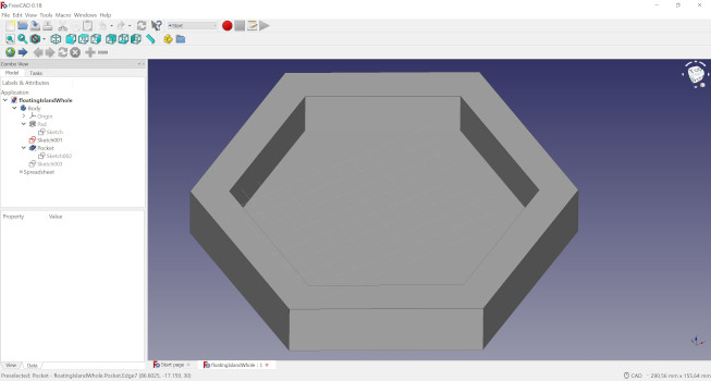
As an individul assignment for laser cutting, I wanted to make a press fit construction in form of the frame of a floating island. Later on this year I would like to organize a workshop with school children, building floating islands, fill them with substrate and plant plants inside. To visualize the idea, I designed the frame in FreeCAD. Here I explained how I designed something else in FreeCAD.
I then moved over to try something else and modeled the parts of this frame in Fusion 360. First step doing this was to create a sketch for the base plate, to create a circumscribed polygon, and to define some parametric dimensions. Therefore, I can just change the size of the base plate by changing the values of the parametric dimensions in the spreadsheet.
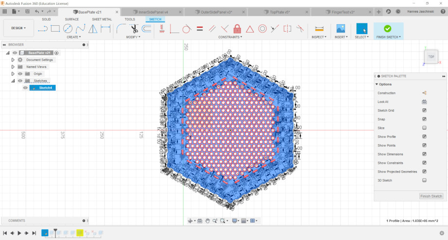
To make a sieflike grid out of hexagonal polygons, I created three of them and then created a rectangular pattern to replicate them in x and y direction.
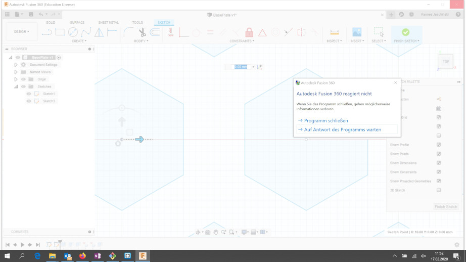
I realised relatively quickly that the my design was a little bit too big and had way too many elements. Fusion crashed several times.
I then, thanks to the parametric design, decreased the size of the base plate and the amount of the polygons forming the sief holes until Fusion ran properly.
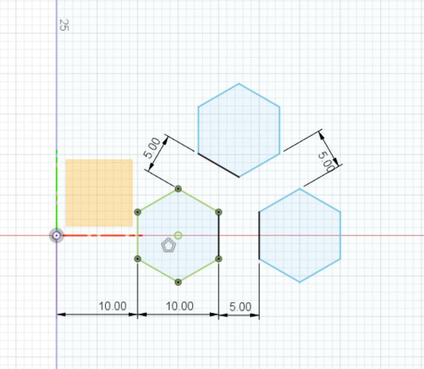
With the line funtion and a polygon that I just created as a construction line I made the slots for the press fits. Of course, for that I used parametric design as well. With the help of the trim function I removed all constructions lines that I didn’t need anymore.
I repeated the same for the top plate and the inner and outer side panels. On the example of the inner side panel the parametric design can be shown easily.
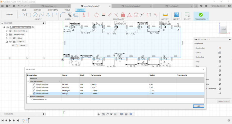
After the kerf test I knew the with of the cut, and therefore, was able to adapt the length of the pins and gaps between the pins to achieve a snug press fit between the different parts.
Other than before with the kerf test, in Rhino I now placed several parts on the sheet that I wanted to cut.
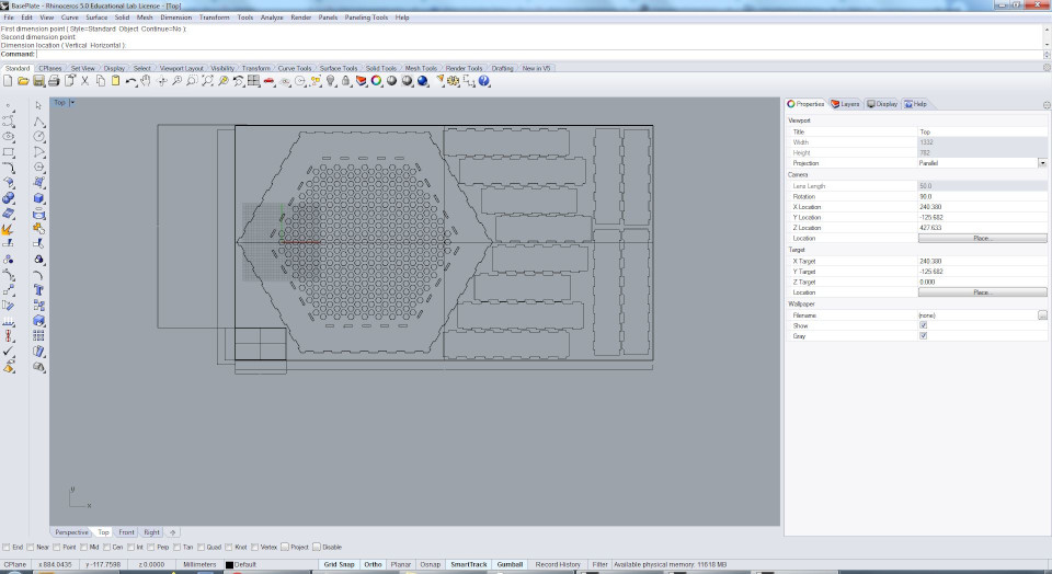
I used the same cutting parameters as I already used for the kerf test since I also used the same material. During the cut of the kerf test the laser cut all the way through the mdf sheet. Unfortunately, during the cut of the parts for the floating island the laser didn’t cut all the way through at some spots.
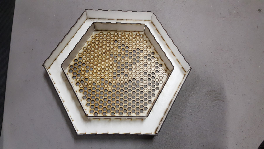
I think that the reason for that might be that the mdf sheet wasn’t perfectly even. I did set the focus again but I might have done it at one extreme of the topology of the slightly uneven plate and the laser dind’t cut through at a different extreme in the other direction. Therefore, some of the hexagons weren’t easy to push out fter cutting.
Downloads
Green FabLab logo
Silhouette Studio file
FreeCAD file
Sketch base plate
Sketch inner side panel
Sketch outer side panel
Sketch top plate
Sketch kerf test