8. Computer controlled machining
When I go scuba diving, I usually go with at least one or two of my friends and go to the lake by car. Taking the wet scuba gear inside the vehicle when returning from the lake always totally fogs up my car.
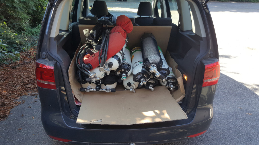
Therefore, I bought a 38 year old Westfalia trailer and fixed it. Of course, when strappping down the gear on the trailer, especially the scuba cylinders, I’m pretty german about it, which takes quite some minutes every time.
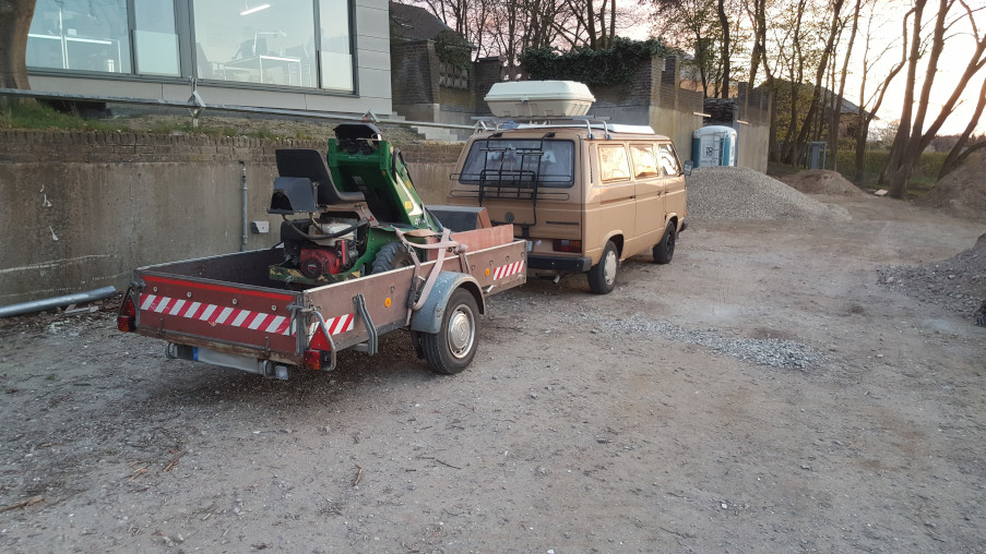
Of course, when strappping down the gear on the trailer, especially the scuba cylinders, I’m pretty german about it, which takes quite some minutes every time.
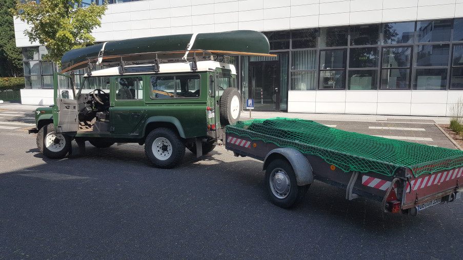
Life would be much easier with a simpler solution to fix the cylinders to the trailer. Since this weeks assignment is about making something big on the CNC router, I jumped at the chance and designed a scuba cylinder rack for my trailer.
Design
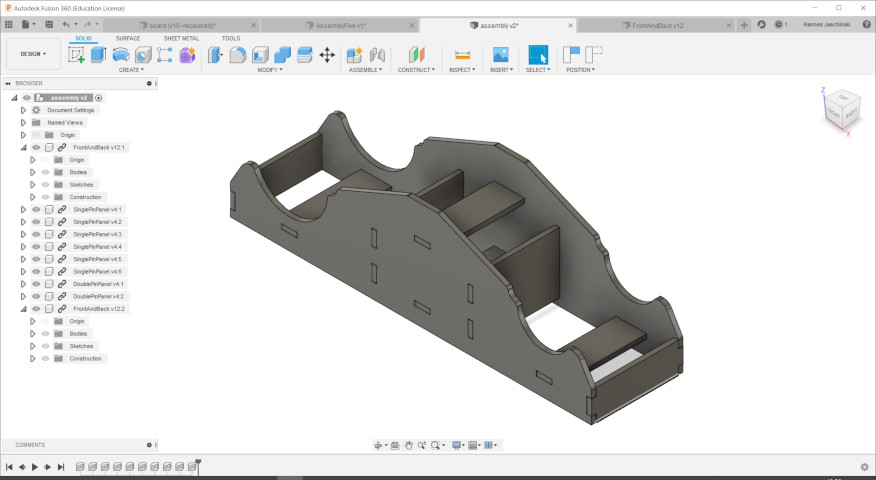
The idea was to use a parametric design to attach CNC milled plywood parts with finger joints to each other. Two parts form the shape of the rack crosswise like the ribs of a ship and a couple of connecting members hold those two parts in place and connect to them with finger joints lengthways.
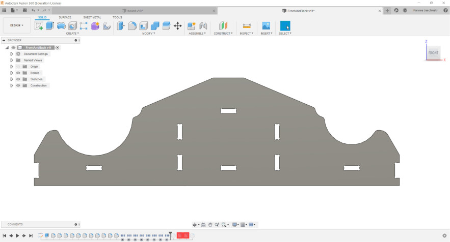
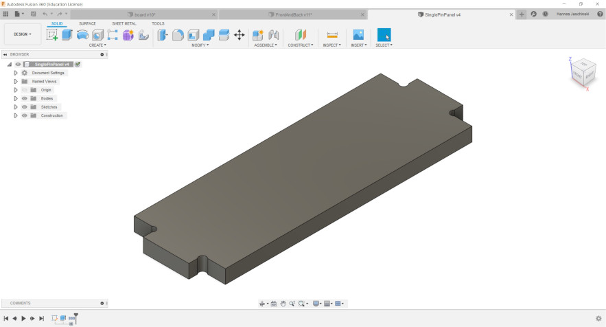
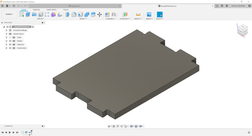
For designing the components, I used Fusion 360. I started by drawing a contact surface with the same angle as the backplate of my twinset scuba cylinders in a sketch. Right next to that surface I made a contact surface for my extra stage tank and on the other side a contact surface for the DPV I’m building for my final project. Those three contact surfaces are designed to fit the shapes of the objects they should hold snugly. Relative to each other, the three contact surfaces are placed so that a single lashing strap going over the three objects from one side to the other has enough contact to them and would keep all of them in place. The whole rack was designed in a way that it fits across the bed of the trailer between two lashing lugs, leaving enough space on either side to hook in the straps. I then designed some sockets fo the fingers of the connecting members and extruded the part to 15 mm, the thickness of the stock material I was planning to use.
The part will be milled with a round end mill, therefore, the sockets for the fingers, coming in perpendicularely, will have round edges. The fingers, on the other hand, are square. To still achieve a snug fit, I will have to mill out some circles around the edges, to generate some clearance for the finger’s edges. A helpful tool for that is the Dogbone Add-in for Fusion 360. It allowed me to make fillets that leace enough space for the finger’s edges.
The same way I also designed the connceting members.
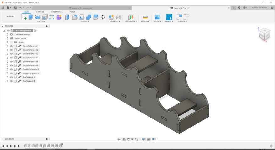
I also designed two cross parts to hold five scuba cylinders for my friends the same way.
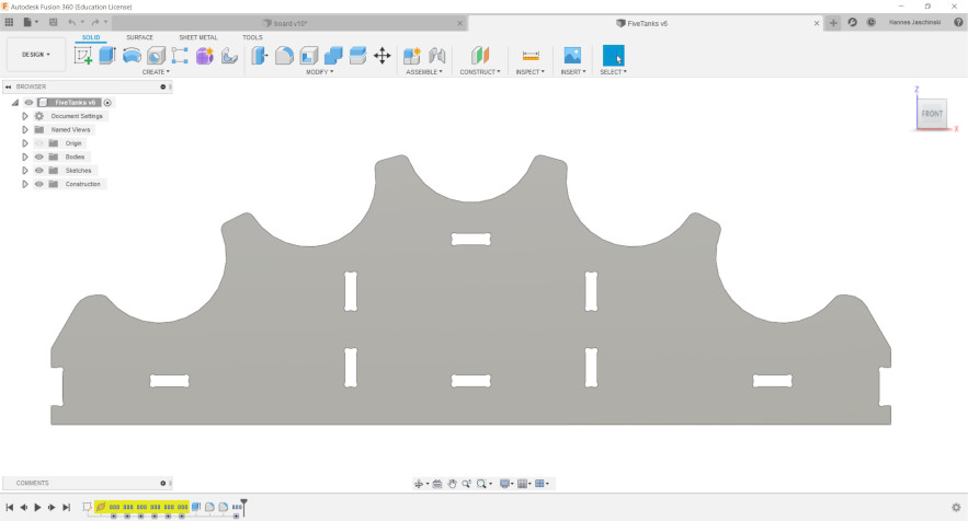
In all skeches I drew points on the outline to define the position of the holding tabs later on.
Preparing the milling
In order to mill the parts, I designed the stock board that I wanted to mill the parts out of. The available board is 2550 x 1250 x 15 mm (length x width x hight). To make my life a bit easier, I oriented the long side on the x axis, the narrow side to the y axis and the hight to the z axis. I placed the parts to be milled in respective numbers inside that board and aligned the top surfaces of all parts.
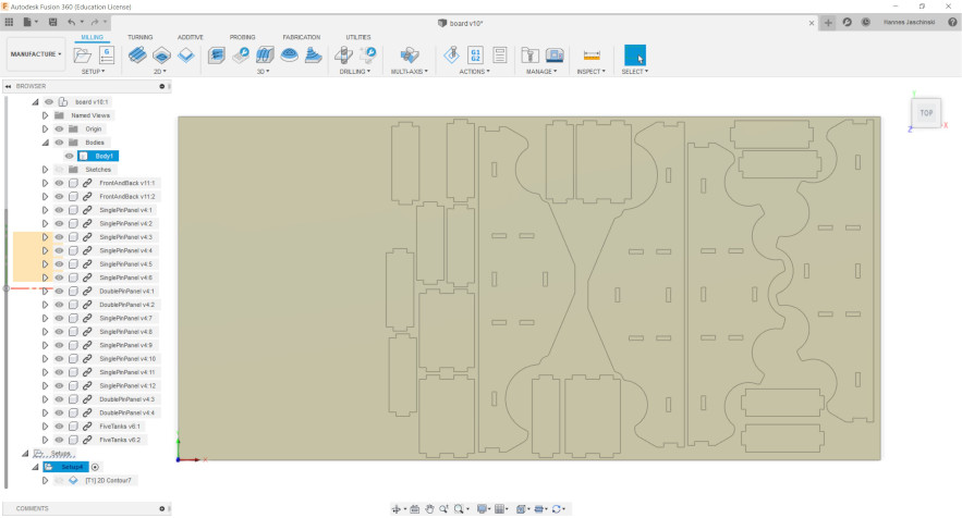
Then I changed from Fusion’s DESIGN mode to the MANUFACTURE mode to create the milling path and started a new setup. As operation type I chose “milling”, as stock I chose “from solid” and picked the board and then fixed the coordinate system of the milling operation. For the router I’m going to use the origin of the coordinate system is in the front right bottom corner. As a model I picked all the parts I wanted to mill.
The next step was creating a 2D Contour. I created a new tool, a cutter with a diameter of 6 mm, selected the 52 contours I wanted to mill and selected tabs. In “Passes” I picked “Multiple Depths”.
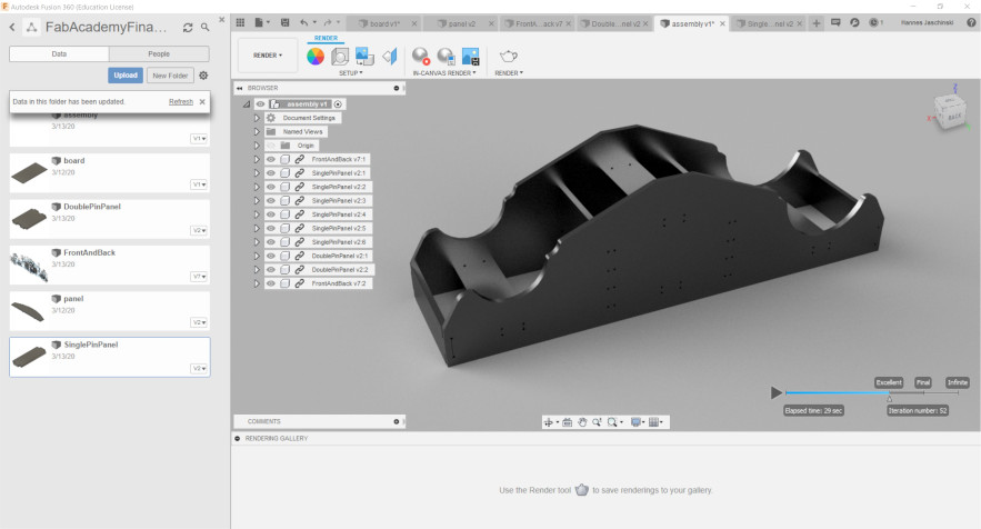
Since I can’t use the machines in the FabLab Kamp-Lintfort due to the global situation, all I was left with was watching a simulation of the milling process and assembling the parts in Fusion.