9. Embedded programming
This weeks assignment was one without any need to work in the FabLab at all. The weather wasn’t bad at all but I worked inside my home anyways.
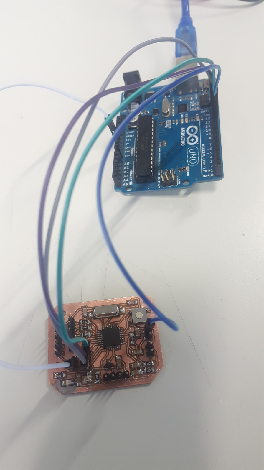
I wrote the code in the Arduino IDE, used an Arduino Uno as a programmer and programmed my boardfrom two weeks ago.
Writing the code
For writing the code, I used the Arduino IDE. My goal was to include my board’s button and its LED and to make the LED react to the button.
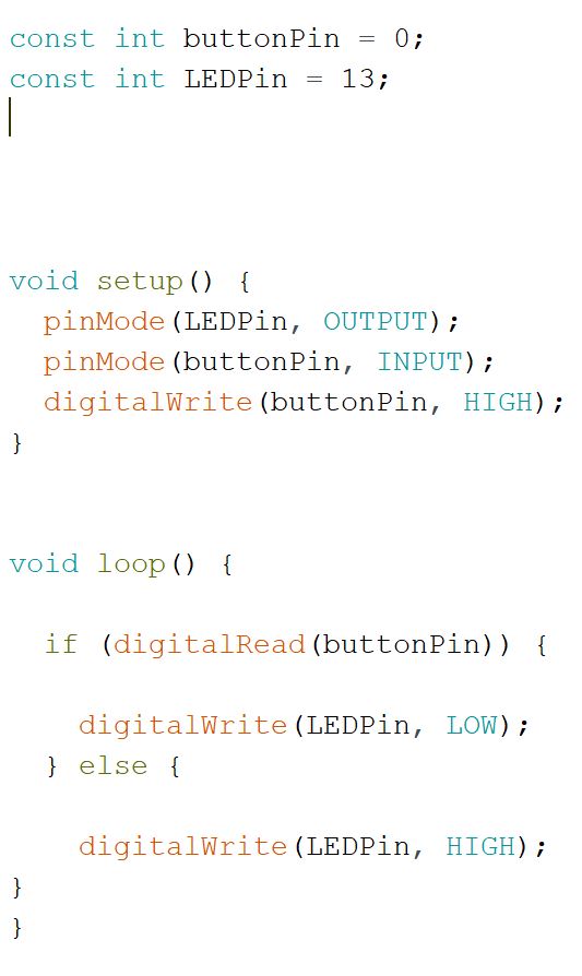
I started my code with the first two lines const int buttonPin = 0; and const int LEDPin = 13; to define those two constants. int stands for integer values. I allocated the pin numbers for the button and the LED. On the ATmega328PB I connected the button to the PD0 pin and the LED to the PB5 pin. Since I programmed the microcontroller with the Arduino IDE, using an Arduino Uno as an ISP, the microcontroller then uses the Arduino labels for the pins. According to a very intelligible explanation I found the according Arduino pins. PD0 refers to pin 0 and PB5 refers to pin 13.
In the void setup() { } I defined the input and the output of the board. pinMode(LEDPin, OUTPUT); defines that the LED connected to the LED pin is the output and pinMode(buttonPin, INPUT);defines that the button is connected to the button pin and serves as an output. The line digitalWrite(buttonPin, HIGH); permanently gives a signal on the button pin. Physically pushing the button would the interupt the signal.
In the main body, a void loop, the actual programm was contained in void loop() { }.
if (digitalRead(buttonPin)) { } does whatever is inside the curly brackets, as long as the button pin reads a signal. In this case, inside the curly brackets I wrote digitalWrite(LEDPin, HIGH); to turn on the LED. The line else {digitalWrite(LEDPin, LOW);} turns off the LED, whenever the button pin signal is interrupted by pushing the button.
Connecting the board
To upload the code to the board, I had to connect it to my computer. Therefore, I connected the board to power and to the programmer, which I then connected to my computer.
To power my board, I used a USB charger. I connected the USB plug of a FTDI cable to it and connected the 1st (black) and the 3rd (red) wire to the GND and VCC of my board. The board responded by having the power LED turned on.
To allow communication between my board and the Arduino, I connected the pin connected to SCK pin of my board to the Arduino’s pin 13, MISO to pin 12, MOSI to pin 11, reset to pin 6 and GND to GND to share a common ground. The Arduino was conected to my computer with an USB cable.
Uploading the code
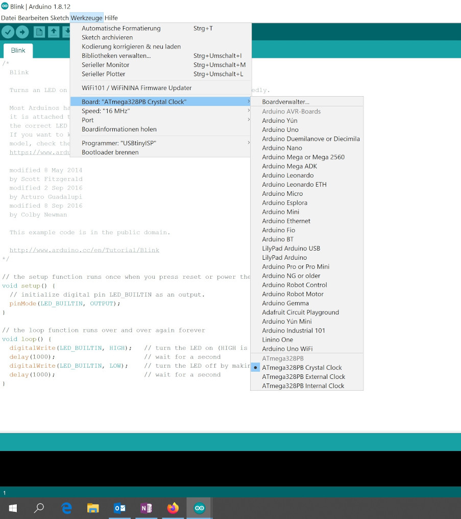
In the Arduino IDE, under tools I changed the board to ATmega328PB Crystal Clock and the speed to 16 MHz. The Programmer was set to Arduino as ISP. Then I programmed the board by clicking on upload with programmer under sketch.
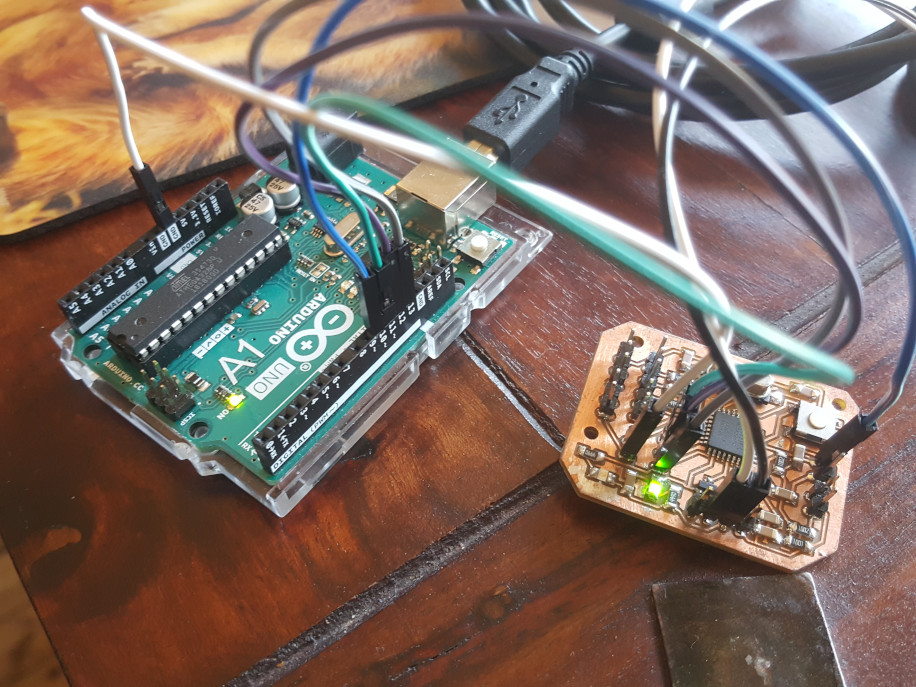
Testing the board
The board then behaved like I wanted it to do. The LED was on and turned off for the time I kept the button pushed.
By changing HIGH to LOW for the if condition in the void loop and LOW to HIGH in the else condition, the LED was off and only turned on as long as the button was pushed.