6. 3D Scanning and printing
3D scanning
As a 3D scan I analysed the head of an African leaffish, Polycentropsis abbreviata. It reaches an average length of 4 to 5 cm and belongs to the family of leaffisches, Polycentridae. Polycentropsis abbreviata uses its protrusible mouth to catch prey and to take up food. This process increases the effective rate of approach to the prey.
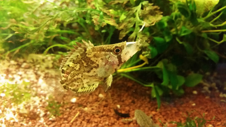
I was very much interested in how this mechanism works, that allows the fish to protrude its mouth about one third of its head’s length. Therefore, I, besides dissection and video analysis, researched this mechanism with the help of µCT scans to get a better understanding of the bone structures that are involved in the movement of the jaws.
µCT
A µCT scan is the combination of many high-resolution x-ray scans from different angles that are merged into a 3D visualisation of the scanned object.
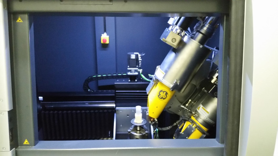
I was using a phoenix|tome|x m which belongs to the FIBRE at the University of Bremen.
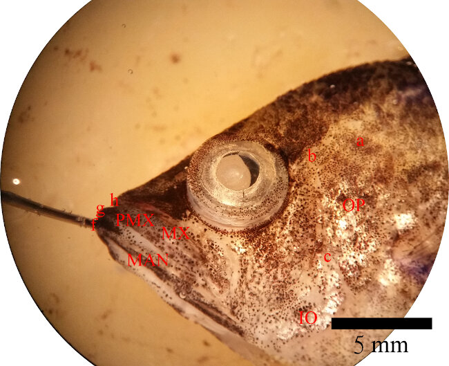
Preparation of the specimen
I seperated the head of an African leaffish that deceased from a natural death between the third and the fourth cervical vertebra on the transversal plane. Inside a film canister I glued two 7 mm long pieces of toothpick to the bottom with some UV-curing glue. I placed the head on the toothpicks with the cut face downwards. A piece of string around the mandible allowed me to pull the underjaw forward from outside the canister. To avoid desiccation of the specimen, and thereby, possibly causing artefacts, I filled the canister with 70 % ethanol and closed the lid.
Scanning
I used an acceleration voltage of 50 kV and a current of 190 µA. The used detector is a dxr-250. With a measurement time of 333.097 ms only one measurement per position was made without using the averaging and the skip function. In one revolution 2024 measurements were made with a resolution of 2024 x 2024 pixels. At a magnification of 14.739333 the maximum resolution wa 13.569135 µm.
I then used the software phoenix datos|x 2 acquisition to run an object recognition and to create a volume data set.
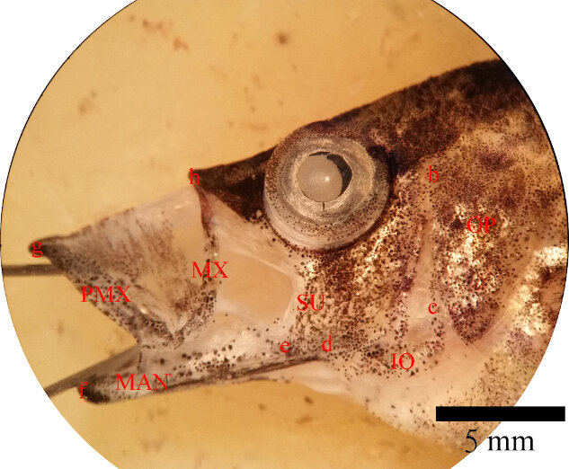
After the first run I did the second iteration with the jaws fully protruded by pulling it forward on the string.
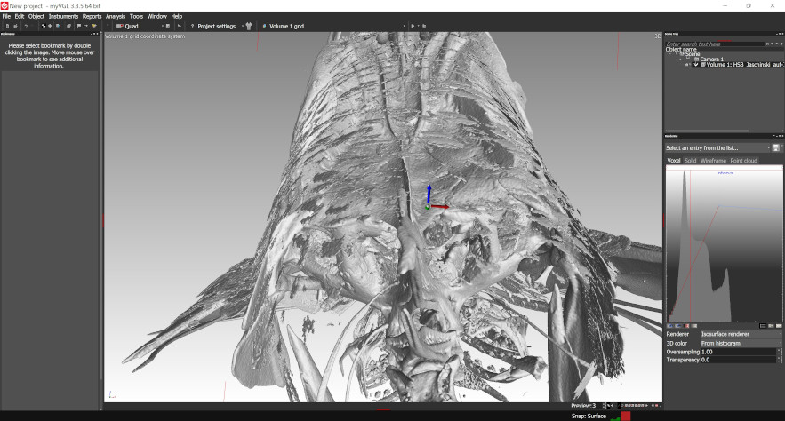
Postprocessing
In the first step the postprocessing of the data set was done with VGSTUDIO MAX. I changed the threshold to manipulate the visibility of tissue depending on its density.
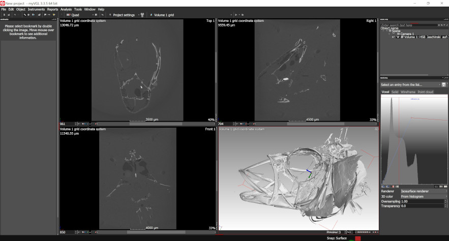
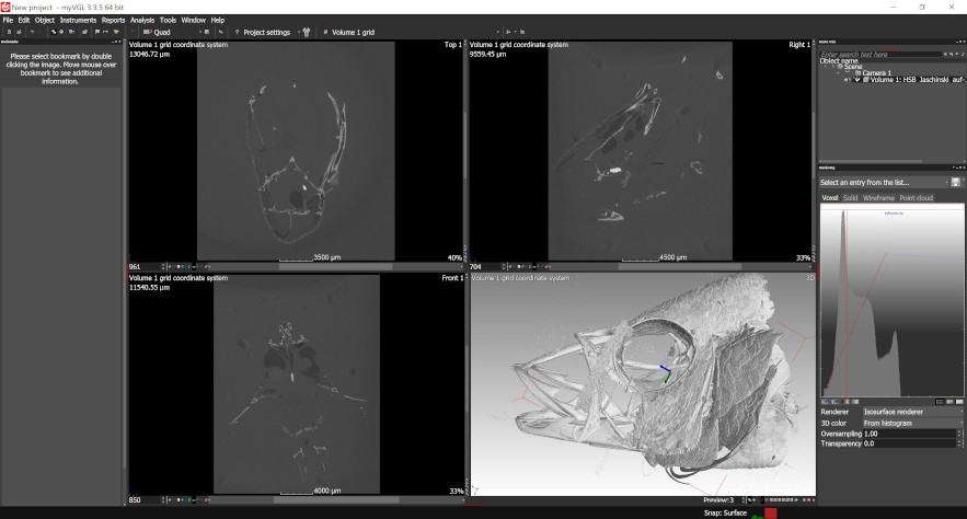
One of the biggest difficulties was that there obviously is a certain overlap in the density ranges of bone structure and the fish’s scales. Therefore, there was no specific threshold where the bone structure was completely visible and the scales disappeared entirely. The trade-off I chose was to forgo a small portion of the bone structure, and therefore, avoid the scales completely.
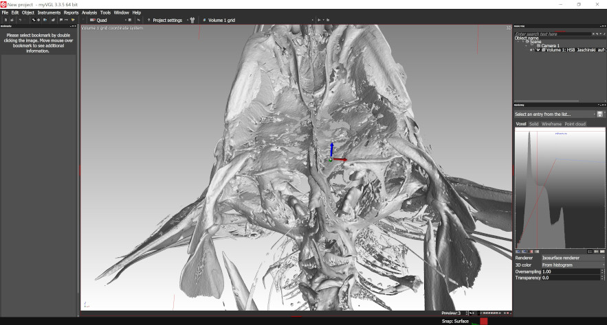
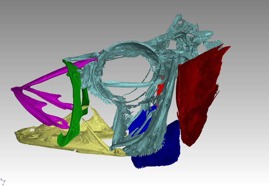
I then segmented the the different bones and labelled them with different colours. This allowed me to export them as individual .stl files.
3D printing
Individual assignment
Modelling the CAD file
This week I tried to use as much time as possible to progress with my final project. This is why I used Fusion 360 to model the kort nozzle and the handle of the DPV I’m planning to make happen. I already designed the main part of the hull for the CAD assignment in FreeCAD three weeks ago.
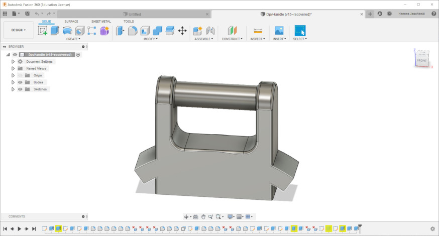
My plan was to design and 3D print the handle of the DPV for this week’s assignment. Since it’s directly connected to the kort nozzle, a nozzle that sourrounds the propeller, and has a very dedicated shape, I also designed that one, to make the handy fit to it with the help of boolean functions.
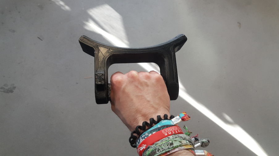
I first modelled the handle and made its bottom part, that connects to the kort nozzle, way longer than it needs to be. Like before, I started with 2D sketches that I then extruded into 3D bodies and joined with the previous body. Making a sketch on a previously designed plane surface and later extruding that sketch in the 3D space made it relatively easy to design the handle, even though its shape could have been simpler. With the help of this approach I also designed the extension that is meant to be used as a mount for the throttle trigger for the right index finger. The fillet function helped me to remove sharp edges and poits with high stress concentrations.
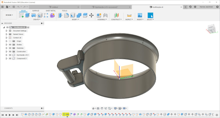
Then I opened a new file to model the kort nozzle. I drew the profile of the nozzle and then rotated it around an axis. By moving the sketch relative to the axis I could determine the diameter of the nozzle. The circular pattern function was a great help to make bolt holes into the skirt in a determined distance.
Time to make my first steps in making assemblies in Fusion 360. I inserted the handle into the current design of the nozzle and moved and rotated it relative to the nozzle to bring both into the posistion and orientation I wanted them to be. To get rid of the overlap of both bodies I used the combine function to perform a boolean operation that cuts away the excessive material on the bottom of the handle.
To get the bolt holes perfectly fitting into the handle, I created rods in the diameter of the holes in the nozzle, alligned them with the holes and extruded them, so that they were even going entirely through the connecting part of the handle as well. After using boolean operations again I ended up with the bolt holes going through the nozzle and the handle like I wanted.
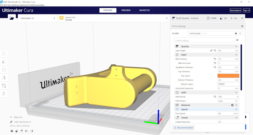
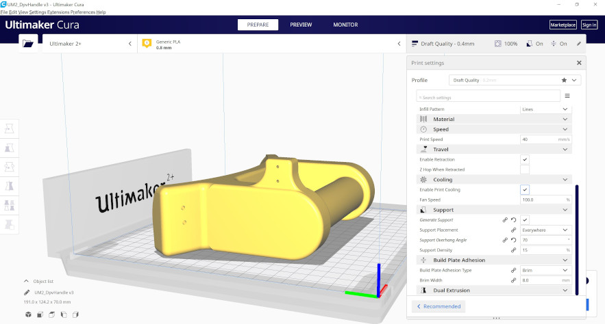
Preparing to print
To prepare the part for printing, I used Cura as a slicer software. I selected the printer I wanted to print with, an Ultimaker S2+, and set the printing settings. I decided to print the part with an infill density of 100 %. Focussing on the mechanical stress caused by the load on the handle, a solid pard without cavities on the inside wouldn’t be necessary. The reason for going for 100 % infill was that I’m planning to also use the DVP in greater depths under water. Hollow structures could gradually fill with water under higher pressure, and therefore, change their buoyancy characteristics. Since a DPV is supposed to be neutrally buoyant, I diceded to make it solid.
Postprocessing of the part
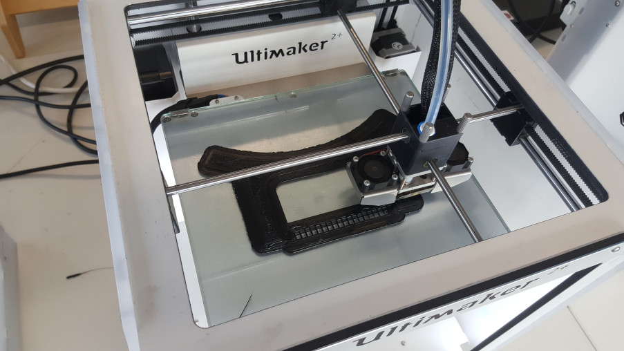
After Printing the part, I took it out of the printer and removed the brim and the support structures with a cutter.
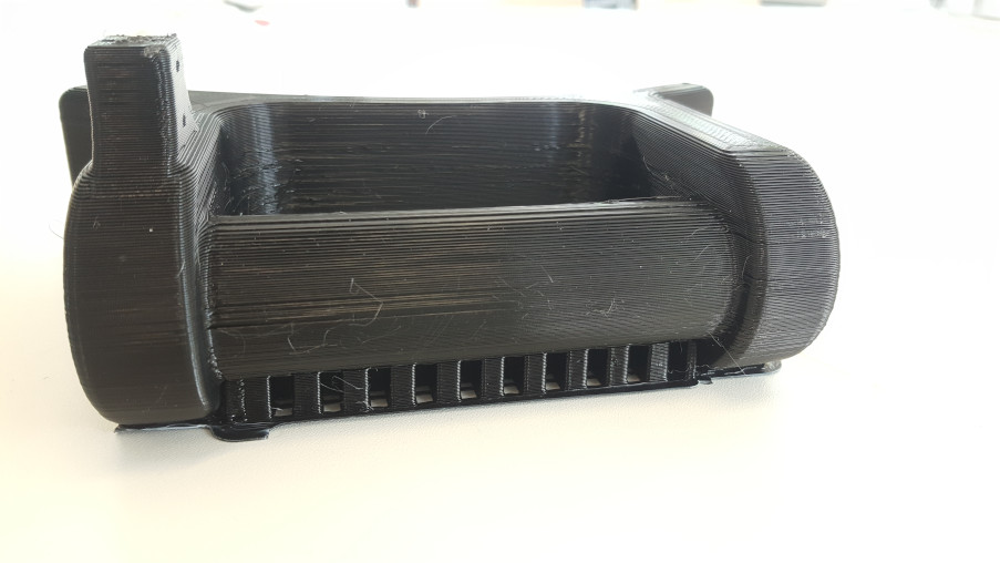
To give it a smooth finish, I treated the surface with sandpaper.
Downloads
compressed .stl files of my scan
.f3d file of the handle and nozzle for my final project